Walkthrough: Build a Project from Scratch
The first hour with HiNC, on nothing but what the installation brings: an empty project built up
into one that plays, on one of the machines HiNC ships. The machine, the spindle, the materials and
the cutter come from the Resource folder HiNC installs; the program is printed on this page. A
new project, then the program, the machine and the spindle, the fixture, the workpiece, the tool,
program zero and the mission, and the project saved. The order is the one that avoids going back —
Project Construction says why, and what a finished project has
to pass; this page is the clicks.
Play the Project and Read the Result comes after this one: it plays the project built here and reads what the run says about the cut.
Before you start
HiNC is running and its page is open in the browser, signed in if your installation asks for it — Installing HiNC on Windows. There is nothing to download.
Spindle Capability and the workpiece's Material appear in the Control Tree only while Preference › Show Physics Options is ticked, which it is unless someone has cleared it — Preferences. The pictures were taken on the finished project, so a picture can already show what a later step adds.
1. Create the project
- File › New. The picker opens at the Admin root, the server's working area; on a new
installation it holds only the
CacheandResourcefolders. - Press New Folder in the picker's toolbar, name the folder
first-project, and open it. - Name the file
Mainand press Create.
A project gets a folder of its own: everything it refers to will be written beside the project file. The new project opens at once, and it is not empty — it carries a fixture and a workpiece with no shape yet, an empty tool house, and a mission of eight commands, two of which name programs that do not exist.
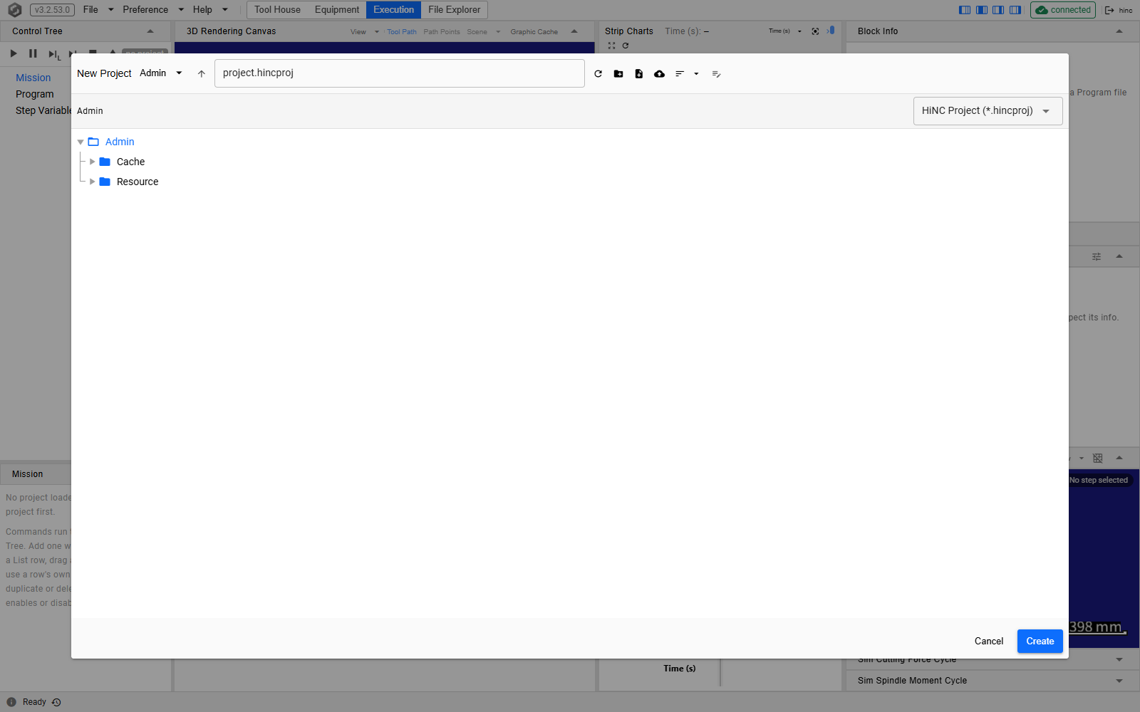
The dialog, and what each entry of the File dropdown does, are Projects.
2. Write the program
The program cuts one circle into the block with a single 12 mm end mill. It takes tool 1
(T01 M06), works in the G54 coordinates, turns the spindle at 5000 rpm with the coolant on,
goes down outside the block's front face to 5 mm below its top, feeds in at 500 mm/min and cuts one
full circle of 11 mm radius (G02 I0.0 J11.) before it lifts away:
%
N0010 G40 G17 G49 G90
N0020 G91 G28 Z0.0
N0030 T01 M06
N0040 G00 G90 G54
N0050 X35. Y-11.7
N0060 G43 Z10. H01
N0070 S5000 M03
N0080 M08
N0090 Z-2.
N0100 G94 G01 Z-5. F500.
N0110 Y-4.
N0120 G02 I0.0 J11.
N0130 G01 Y-10.
N0140 Z-2.
N0150 G00 Z10.
N0160 M09
N0170 M05
N0180 G91 G28 Z0.0
N0190 M30
%
A program is a text file in the project's folder, and File Explorer writes one:
- Press File Explorer on the menu bar. The root selector at the left of its toolbar reads Project, the new project's folder.
- Press New Folder (the folder icon with a plus sign), change the name to
NCand press OK. Then click the folder's name — not the arrow beside it — so that the path above the list reads Project / NC. - Press New File (the page icon with a plus sign), change
new.txttocircle.ptpand press OK. - Click
circle.ptp, and it opens in the editor beside the list. Click into the editor, paste the program above, and press Save over the editor.
Without Auto Save, the text reaches the file only when you press Save: Ctrl+S is the browser's own key here. Opening another file or leaving the page asks whether to discard the change; reloading or closing the browser tab does not. With Auto Save ticked over the editor, every pause in typing saves, and Save is disabled.
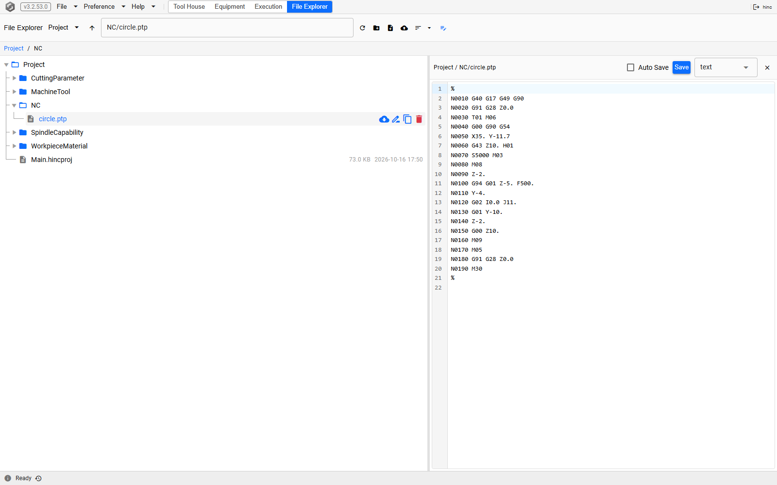
The toolbar's other buttons, and the row actions, are File Explorer.
3. The machine and the spindle
- Press Equipment, select Mechanism › Machine Tool, press its Object Management
(
⋮) button and choose Load. The picker opens on the shipped machines, underResource/MachineTool. - Open
Table-B1.default, tickTable-B1.mtand press Load. A small five-axis machine — X, Y and Z, a B head and a C table — is copied into the project and becomes its machine. - Select Spindle Capability, press its Object Management button, choose Load, and pick
FANUC-aT12-12000i.default.SpindleCapabilityfrom the shipped spindles. Like the machine, it is copied into the project, underSpindleCapability.
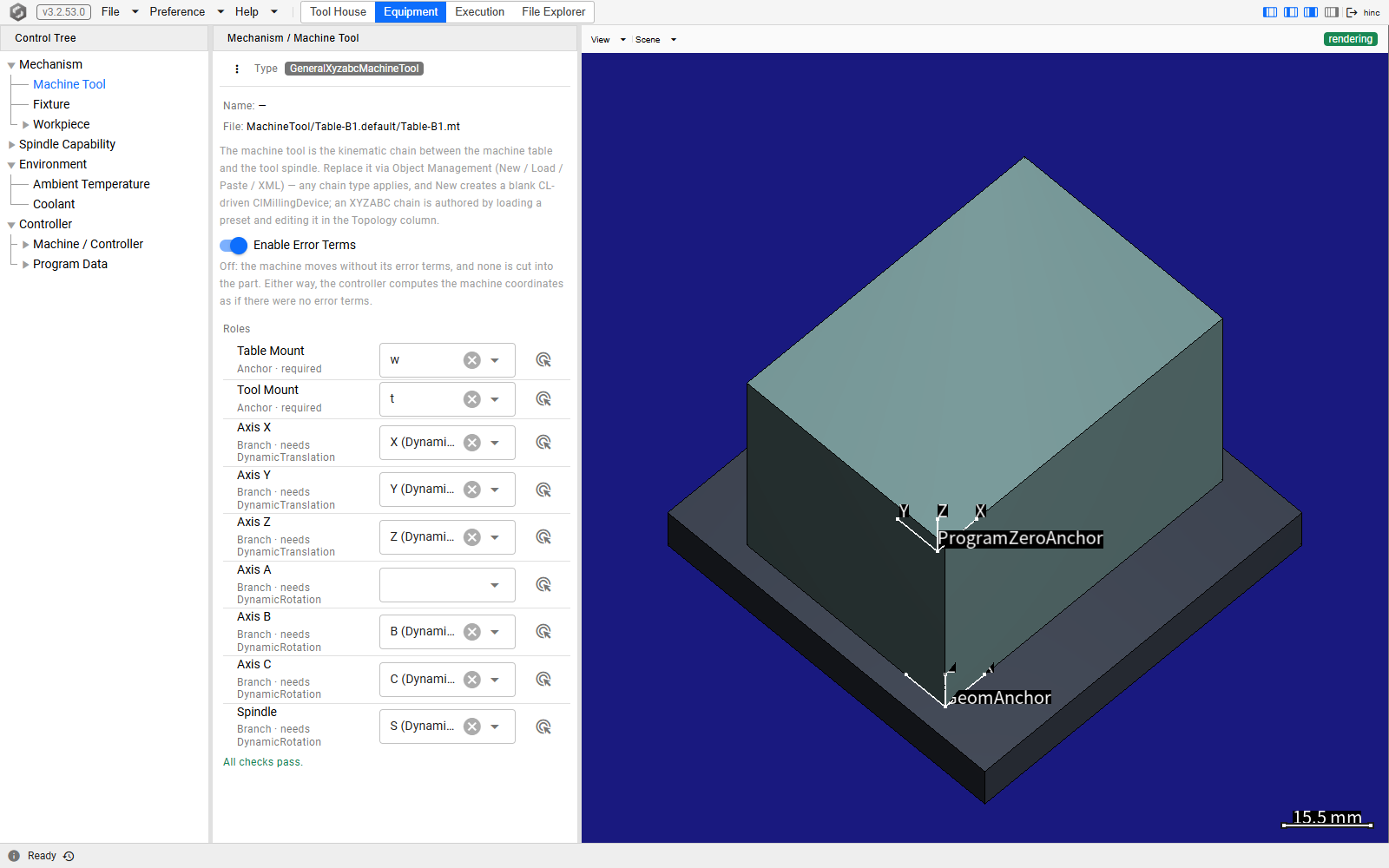
Leave Environment › Coolant as it is: every project starts with the values of a water-soluble coolant, saved in the project rather than loaded from a coolant file. Machine Tool, Spindle Capability and Coolant cover each item.
4. The fixture
The fixture's shape and where it holds the workpiece are both set in the Topology column, the fourth column of the Equipment page.
- In the graph's Fixture cluster, click the anchor badged Fixture · Geometry Anchor. In the
card below the graph, set Geometry type to Box3d, with Min
(-40, -40, 0)and Max(40, 40, 10)— an 80 × 80 × 10 mm plate standing on the table. - Click the branch from it to the anchor badged Fixture · Workpiece Mount, set its
Transformer type to Static Translation, and enter
(0, 0, 10): the workpiece sits on the plate's top face, at its centre.
Fixture is the item, and Anchors and Roles the card and the order the branches go in.
5. The workpiece
Under Mechanism › Workpiece in the Control Tree:
- Raw Geometry: set Geometry type to Box3d, then select the Box3d node beneath it
and enter Min
(0, 0, 0)and Max(70, 50, 50)— the stock, a 70 × 50 × 50 mm block of aluminium. - In the Topology column's Workpiece cluster, click the branch to Workpiece · Fixture
Mount and enter
(35, 25, 0): the block's bottom face, at its centre, is what sits on the fixture. - Click the branch to Workpiece · Program-Zero Anchor and enter
(-2, 0, 50). That is where the program has itsX0 Y0 Z0: on the block's top face, at its front edge, 2 mm to the left of the block. - Material: in Workpiece Material, Select › Browse Resource… and pick
Al6061T6.default.WorkpieceMaterial; in Cutting Parameter, pickAl6061T6.default.mpthe same way.
Target Geometry stays empty. It holds the finished part's model, drawn in the same frame as the stock, when there is one; a project plays without it, and Geometry Validation is what it is for. Mesh is left at the project's default, an Initial Resolution of 0.125 mm.
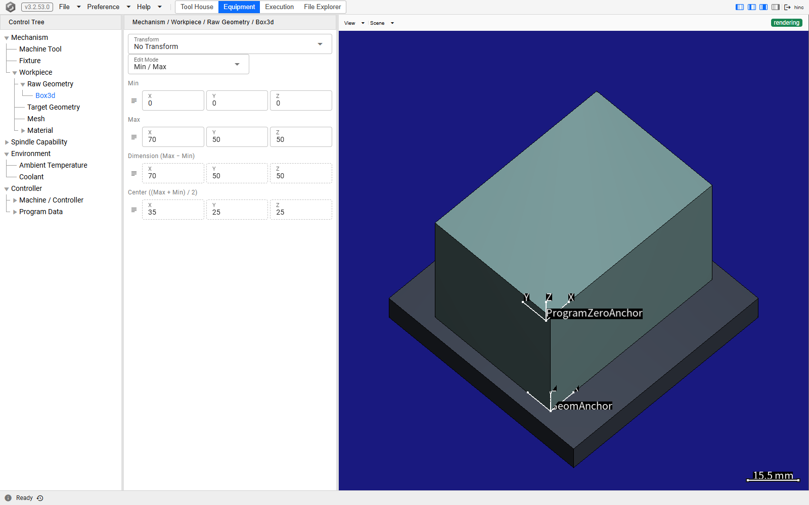
Workpiece is the item. Where program zero has to go, and why it comes from the program rather than from the stock, is Program Zero Alignment.
6. The tool
The tool house is the project's set of tools, and it starts empty. Its one tool here is a cutter HiNC ships, put in a holder:
- Press Tool House, then New Tool. T1 appears in the list, empty.
- In T1's Control Tree select Cutter, press the Object Management (
⋮) button at the head of its editor and choose Load. The picker opens on the shipped cutters, underResource/Cutter. - Tick
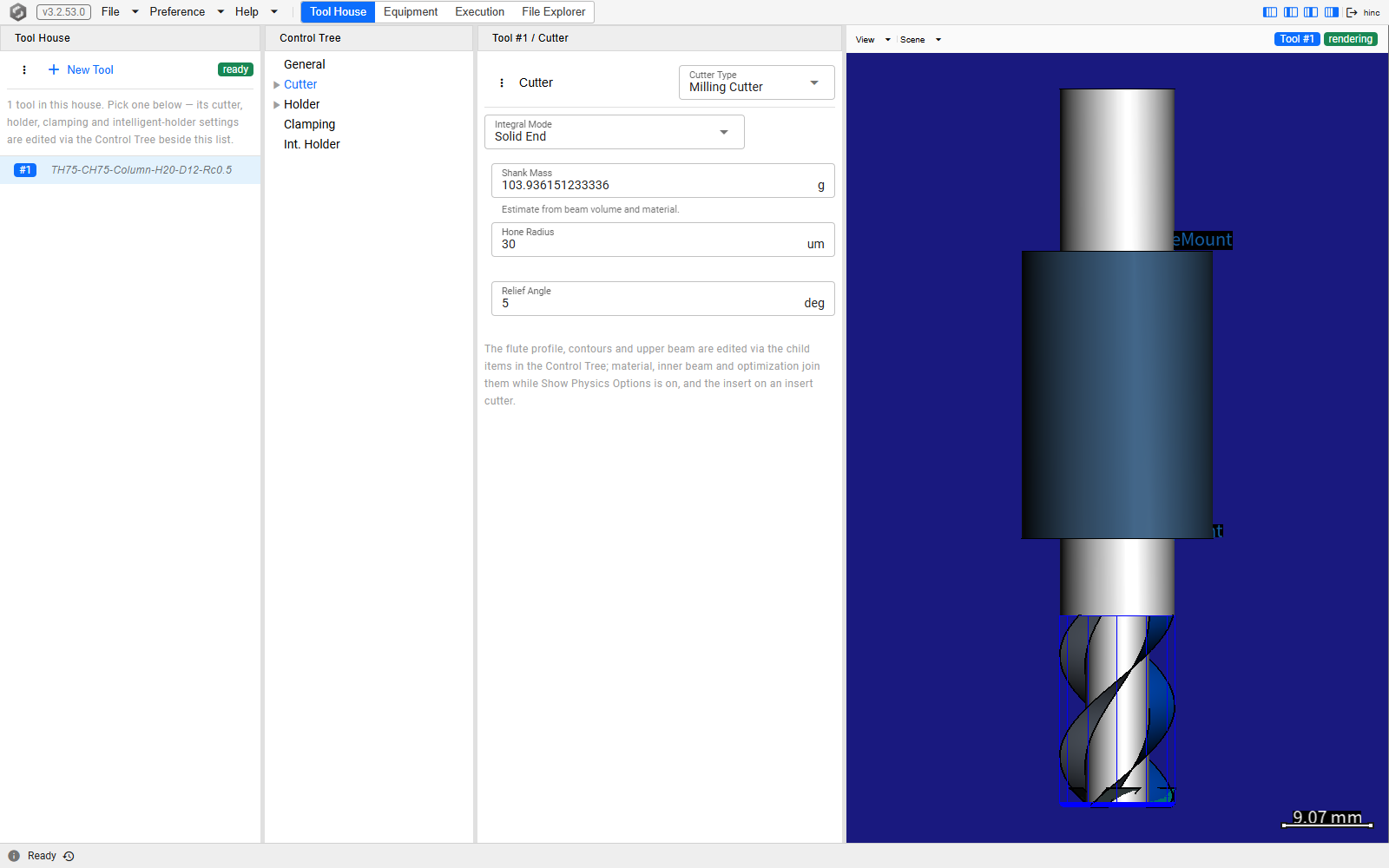
D12-Rc0.5-CH20.default.Cutterand press Load. Cutter Type turns to Milling Cutter, the cutter's sections grow beneath it in the tree, and the canvas draws it: a 12 mm three-flute end mill with a 0.5 mm corner radius and a 20 mm length of cut, its shank 12 mm across up to 75 mm above the tip, in the carbide gradeWC-Co6-800nm. - Select Holder and set Holder Type to Cylindroid Holder. Select Geometry beneath it
and overwrite its two rows, a placeholder, with
0,10and30,10: a holder 20 mm across and 30 mm long, its nose atZ = 0. - Select Clamping and enter Exposed Cutter Height
28: the tip stands 28 mm out of the holder's nose, the 20 mm of flutes and 8 mm of shank.
A cutter file holds the cutter alone, which is why the holder and the clamping are set by hand. The cutter is copied into the project, so the project does not depend on the file it came from. Cutter covers each node, and Build a Cutter and Holder builds the same tool from nothing.
7. Program zero onto the work offset
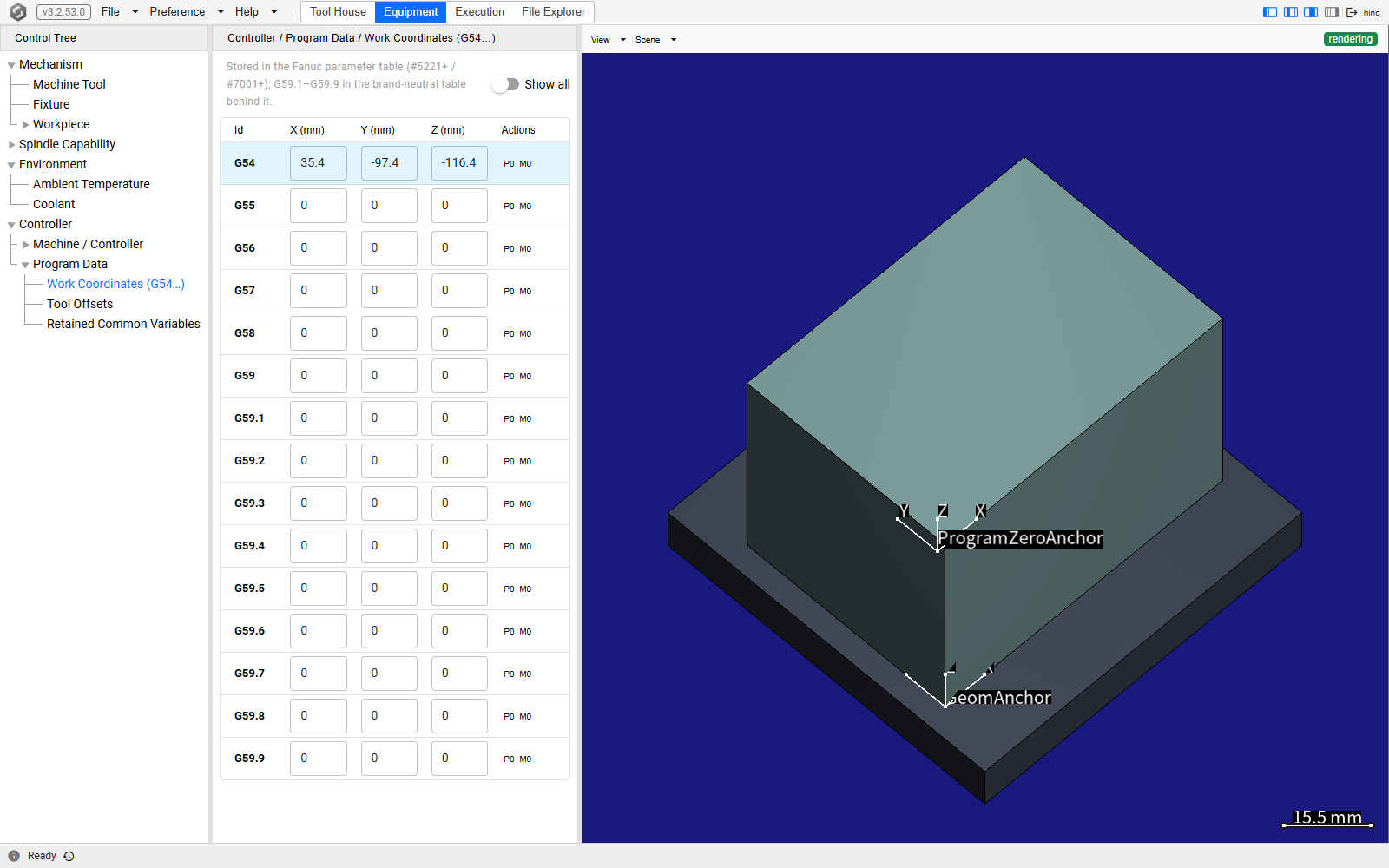
The program selects G54, so that row of the controller's work-offset table has to say where program
zero is on this machine.
- In Equipment, select Controller › Program Data › Work Coordinates.
- On the
G54row, press P0.
The row now holds the machine position at which program zero sits, which is what an operator would key in after touching off on the part.
The other direction — keeping a recorded offset and moving the part onto it — is Program Zero Alignment.
8. The mission
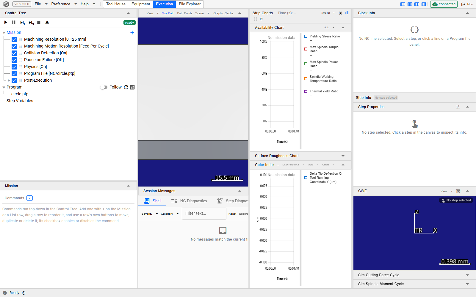
- Press Execution. The Mission starts with five Setup commands, then Program File [NC/NC-File-Name-1.nc] and Program File [NC/NC-File-Name-2.nc], then Post-Execution.
- Select the first Program File and pick
NC/circle.ptpin its editor. - Press Delete on the second Program File's row and confirm.
Building a Mission covers the list, and A Mission That Resumes the shape it grows into on a longer job.
9. Save it
File › Save, then File › ReLoad. A project that comes back from its own file with no message is built.
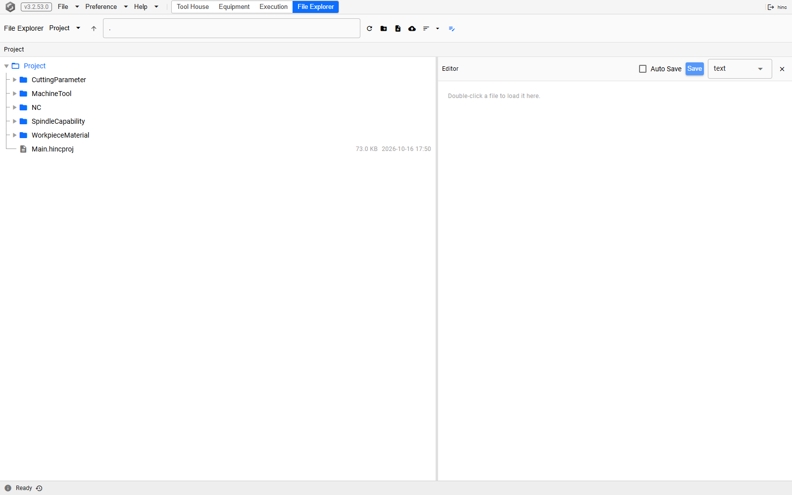
The folder now holds what the project refers to: the program you wrote, the machine under
MachineTool, the spindle under SpindleCapability, and the workpiece material and cutting
parameters under their own folders. The fixture, the tool and everything else are written into the
project file itself.
Where to go next
- Play the Project and Read the Result — this project played: its mission, the Availability Chart, a step's details and the messages, and the cutter given another grade.
- Build a Cutter and Holder — the tool this walkthrough loaded, built from nothing in the same project.
- Project Construction — the same build as a method: the order, the mission shape for a long job, and the replay that says a project is finished.
- Project Data Checklist — what to collect from the machine owner before a real project is built.
- Building the Workpiece from a Reference Mesh — when the part arrives as one mesh from CAM, and program zero has to be found in it.