Walkthrough: Play the Project and Read the Result
The project built in Build a Project from Scratch, played: read its mission, play it, read the result — the Availability Chart, one step in detail, the messages — then give the cutter another grade and play it again. Every step here is a click in the browser; what a screen means is left to the Manual and Technique pages each step links to.
Before you start
Build a Project from Scratch comes first, and its project is open:
the first row of the File dropdown names first-project. If it is not, File › Load: the
picker opens in the folder of the project now open, or at the Admin root when none is, so go up
to Admin if need be, open first-project, tick Main and press Open.
The run in step 2 is short — one program of 1,087 steps, the stock meshed at 0.125 mm. The Availability Chart in step 3 and the cutter's Material in step 4 are on screen while Preference › Show Physics Options is ticked, which it is unless someone has cleared it (Preferences).
1. Read the mission
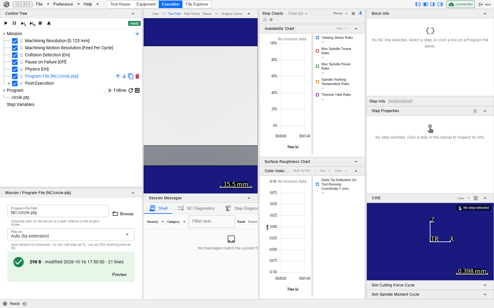
Press Execution on the menu bar. The Mission branch at the top of the Control Tree is the list of commands a run plays, top to bottom, and only the ticked ones run.
This one is what every new project starts with, less the program the build deleted. Five Setup commands set how the run is computed: Machining Resolution [0.125 mm], the size of the mesh the stock is cut in; Machining Motion Resolution [Feed Per Cycle], how finely the motion is cut into steps; Collision Detection [On]; Pause on Failure [Off], so a failure is reported without stopping the run; and Physics [On], the forces, the temperatures and the ratios read in step 3. Program File [NC/circle.ptp] plays the program, and Post-Execution would write files out once the run ends — none of its outputs is ticked. Select the Program File, and its editor shows the file it plays: its path, how it is read, and its size, time and 21 lines, with Preview to open it.
Building a Mission covers the list, and The Other Commands the commands a longer job adds.
2. Play it
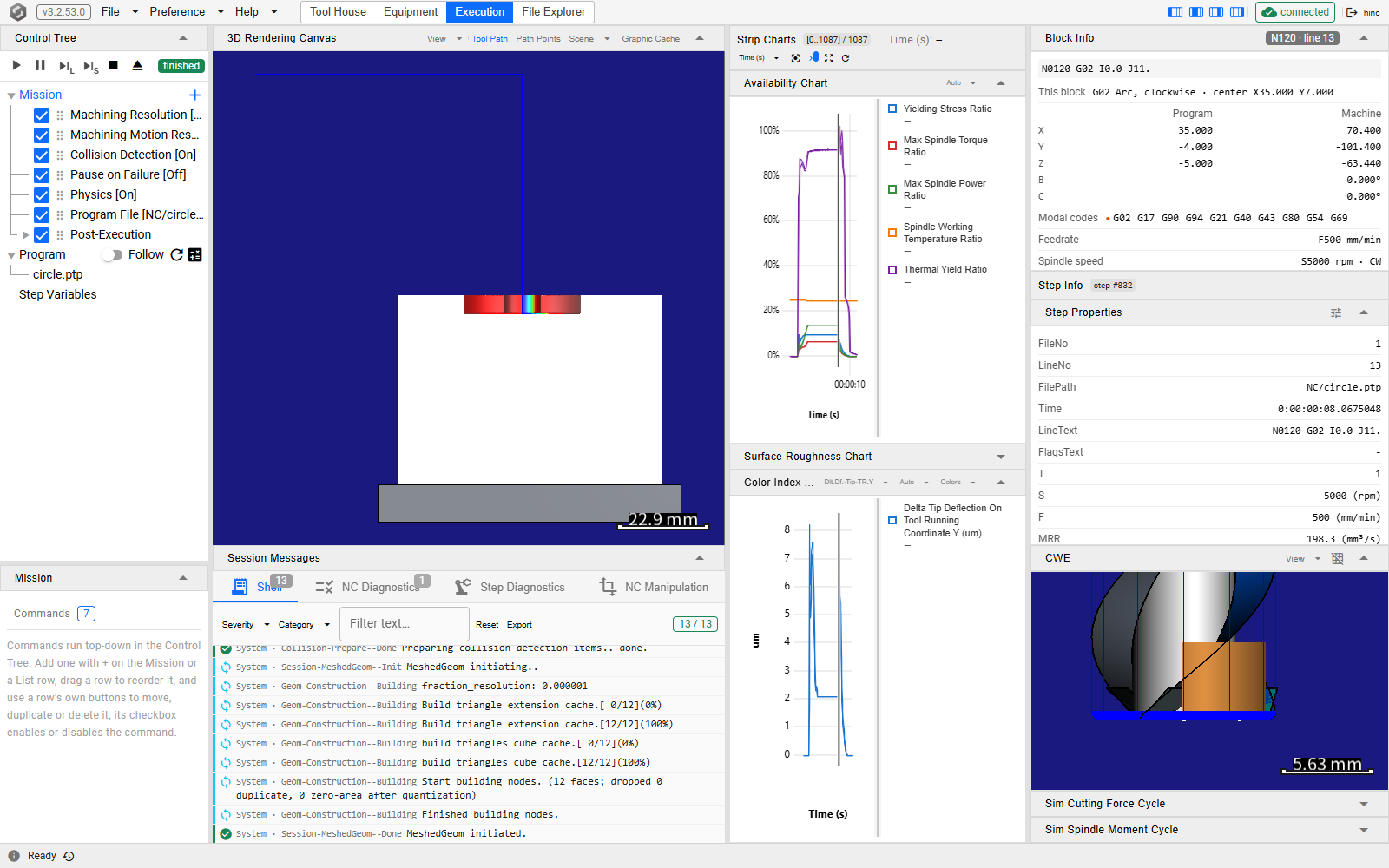
Press Start — the ▶ button at the top of the Control Tree, or F5. The badge beside the buttons turns from ready to running, the tool path and the cut appear on the canvas, and the strip charts beside it fill from the left as the run goes. The badge reads finished when the program has played: 1,087 steps, about 11 seconds of machining.
While it runs, F5 is the browser's reload, not Start — press Pause (F6) first if you want to stop and look. Starting and Stepping has the rest of the transport.
3. Read the result
Start with the Availability Chart, the top strip chart. Its five ratios compare what each step asked of the cutter and the spindle with what they can give, and 100 % is the level each is read against. They do not all mean the same thing when they cross it:
- Yielding Stress Ratio, Max Spindle Torque Ratio and Max Spindle Power Ratio are about breaking. One of them above 100 % for longer than a step puts the cutter at risk of snapping, or the spindle of stalling. In this run all three stay far below it, under 15 %.
- Spindle Working Temperature Ratio is the spindle's own warming against the range it is rated to work in; here it stays near 25 %.
- Thermal Yield Ratio is about the cutting edge softening under its own heat. Above 100 % the edge deforms and wears faster, but nothing breaks at once — it is a long-term measure. In this run it climbs once the cutter is in the block, holds near 90 % through most of the circle, and goes just over 100 % in a few short bursts toward the circle's end — fourteen steps in all, the highest at 102.5 %.
What each ratio means, and what to do about one that is too high, is Evaluating Process Machinability.
Click the chart where the Thermal Yield Ratio is highest. A click selects that step, and the Step Info column on the right fills with it. Block Info, at its top, is the NC line that produced the step as the simulator read it: the block itself, what it does — here a clockwise arc —, where it leaves the tool in program and machine coordinates, the modal codes in force, and the feed, spindle speed, tool, offsets and coolant. Below it, Step Properties lists the step's own values and CWE draws what the cutter was touching. Hovering over the chart marks the same step on the tool path in the canvas.
Watching the Run covers the charts and the canvas, and Inspecting a Step the Step Info column.
Then read the messages. The Shell tab under the canvas lists the run's messages, and one of
them is a warning: StrokeLimit--Unconfigured. The shipped machine has no travel limits entered for
X, Y and Z, so the run cannot tell whether a move along them leaves the machine's travel; it changes
nothing about the cut. The one line under NC Diagnostics only records that the program has 21
lines.
On a project of a real machine, enter the limits under the controller's Machine Limits
(Stroke) — Controller. Any other warning points at something in
the build. What each tab collects is Messages and Logs.
4. Give the cutter another grade and play again
The Thermal Yield Ratio compares the edge's temperature with how much heat its material can take,
so it answers to the cutter's material as much as to the cut. The cutter loaded in the build is a
plain carbide grade, WC-Co6-800nm — the usual baseline when a cutter maker's figures are not
known. Give it a finer grade from the shipped library and play the same program again:
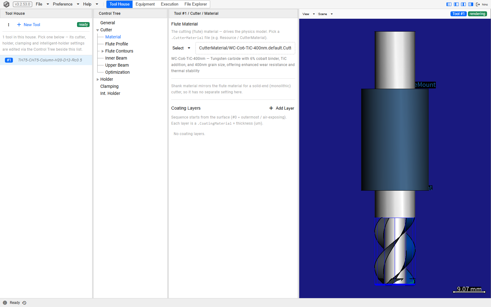
- Press Tool House, select T1, and in its Control Tree open Cutter › Material. Under Flute Material, the file field reads In the cutter itself (no file) — the grade came inside the cutter file — and the line under it names the grade.
- Open the Select dropdown beside that field, choose Browse Resource…, and pick
WC-Co6-TiC-400nm.default.CutterMaterial. The field now names the file, copied into the project'sCutterMaterialfolder, and the line under it the grade now in force. - Press Execution, press Reset — the ⏏ button at the top of the Control Tree — then Start.
Reset first: a finished run has to be reset before Start plays again from the uncut block. When the run finishes, the Thermal Yield Ratio has come down by about an eighth across the run and stays under 100 % throughout, peaking near 89 %; the three breaking ratios have barely moved, because they were never the problem.
Change the grade only to the one the real cutter is made of — a maker's figures, or a cutter the shop knows to run this cut without its edges wearing early. Reaching for a stronger grade to make a chart look better describes a cutter nobody owns. The thermal defaults are conservative on purpose, so a maker's recommended conditions often read above 100 %; when the shop's own experience says a cut like this one is fine, the Thermal Plastic Deformation section of Evaluating Process Machinability says how to bring the material's figures into line, and what else lowers the ratio: a slower spindle, and coolant aimed at the edge. The levers on the breaking side — a shorter flute, a thicker core — are Cutter Adjustment Levers for Force Reduction.
The change lives in the open project until you save it: File › Save keeps it, and File › ReLoad discards it. Discard it before the next walkthrough, which builds a tool to T1's sheet.
Where to go next
- Build a Cutter and Holder — the tool this project plays, built from nothing beside it.
- NC Optimization — adjusting the feed rates so the ratios stay under their limits.
- Geometry Validation — comparing the machined block with the finished part's model, once a project carries one as its target.
- Project Construction — how a project is built so that it is finished, and the mission shape that makes a long job restartable.