Walkthrough: Build a Cutter and Holder
The tool of Build a Project from Scratch built again from
nothing, as a second tool beside it in the same project: a 12 mm three-flute end mill with a 0.5 mm
corner radius, clamped in a plain cylindrical holder. Each step fills one node of the new tool's
Control Tree, in the order the tree lists them; the end compares the result with T1, whose cutter
was loaded from the shipped D12-Rc0.5-CH20.default.Cutter, and plays the program on it.
Cutter says what every node holds, and
Cutter Geometry what each quantity means; this page is the clicks.
Before you start
Build a Project from Scratch comes first: first-project is open,
and its tool house holds T1, the shipped cutter in its holder. If
Play the Project and Read the Result gave T1 another grade, File ›
ReLoad first. The new tool is built to T1's sheet, so the two can be compared node by node at the
end:
| On the sheet | Value |
|---|---|
| Cutting envelope | Column APT: diameter 12 mm, length of cut 20 mm, corner radius 0.5 mm |
| Flutes | 3, ground alike |
| Side edge | constant helix: helix angle 50°, radial rake 15°, radial relief 5° |
| Bottom edge | slide: outer radius 5.5 mm, cutter length on bottom projection 5 mm, eccentric angle 15°, disk angle 1.5°, axial rake 50° |
| Shank above the flutes | Ø12 mm, from 20 mm to 75 mm above the tip |
| Cutting edge | hone radius 30 µm, relief angle 5° |
| Material | the library's WC-Co6-800nm |
| Holder | a cylinder 20 mm across and 30 mm long |
| Stick-out | 28 mm from the holder's nose to the tip |
Show Physics Options has to be ticked in the Preference dropdown: the cutter's Material, Inner Beam and Optimization nodes are in the tree only while it is — Preferences. Nothing below is kept until step 9 saves the project: a Load or ReLoad before then drops the new tool.
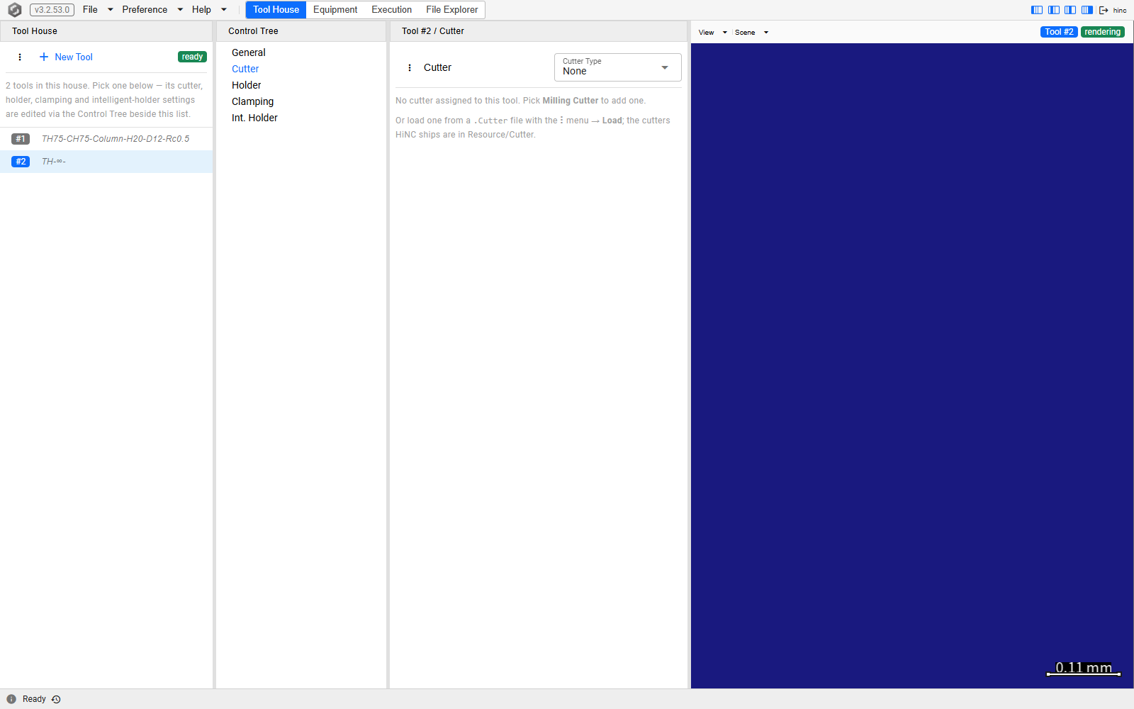
The first picture shows the new tool as it arrives; the others show it finished, at the node each step fills.
1. A new tool
- Press Tool House, select T1 in the list, and select Cutter in its tree.
- Press New Tool.
T2 appears in the list, selected, and the editor stays on Cutter — picking a tool keeps the node
you were on. The new tool is empty: Cutter Type reads None with a line saying no cutter is
assigned, and a second line points at the Object Management (⋮) button's Load — how T1
got its cutter, from a file. There is no holder either, the canvas draws nothing, and the list shows
a placeholder abstract note until the tool has a cutter to describe.
T2 just after New Tool, at /tool-house/2/cutter.
2. The cutter
- On Cutter, set Cutter Type to Milling Cutter. The node grows its sections beneath it — Material, Flute Profile, Flute Contours, Inner Beam, Upper Beam and Optimization — and shows Integral Mode Solid End, which is right for a one-piece end mill.
- Hone Radius already reads 30 and Relief Angle 5, the sheet's values. Shank Mass stays an estimate, recomputed as the cutter's geometry and material arrive.
3. The cutting envelope
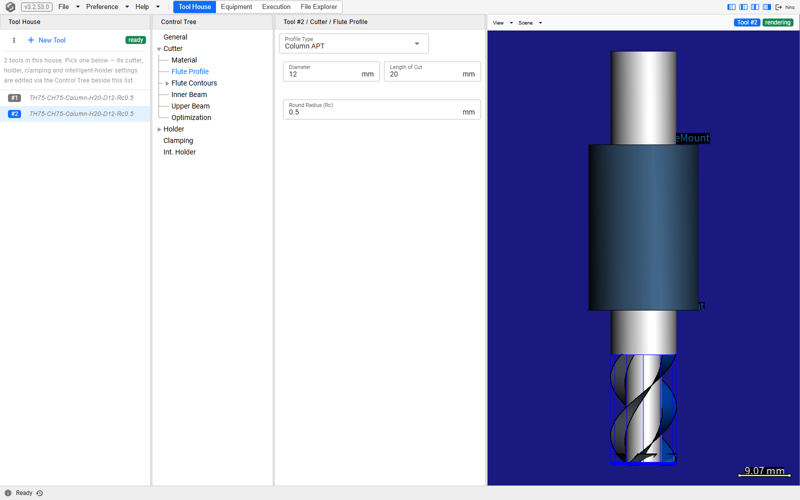
- Select Flute Profile and set Profile Type to Column APT.
- Enter Diameter
12, Length of Cut20and Round Radius (Rc)0.5.
From here on the list row's abstract note describes the cutter, and the canvas draws it.
T2's Flute Profile, at /tool-house/2/cutter/profile.
4. The flutes
Flute Contours is a small tree of its own: the fluting type, then the flutes, then each flute's side and bottom edge.
- Select Flute Contours and set Fluting Type to Uniform (shared baseline) — every flute ground alike. A Uniform Fluting node appears beneath it.
- Select Uniform Fluting and enter Flute Number
3. - Unfold it. Baseline Contour is the one contour the three flutes share; leave its Flute Offset Angle at 0.
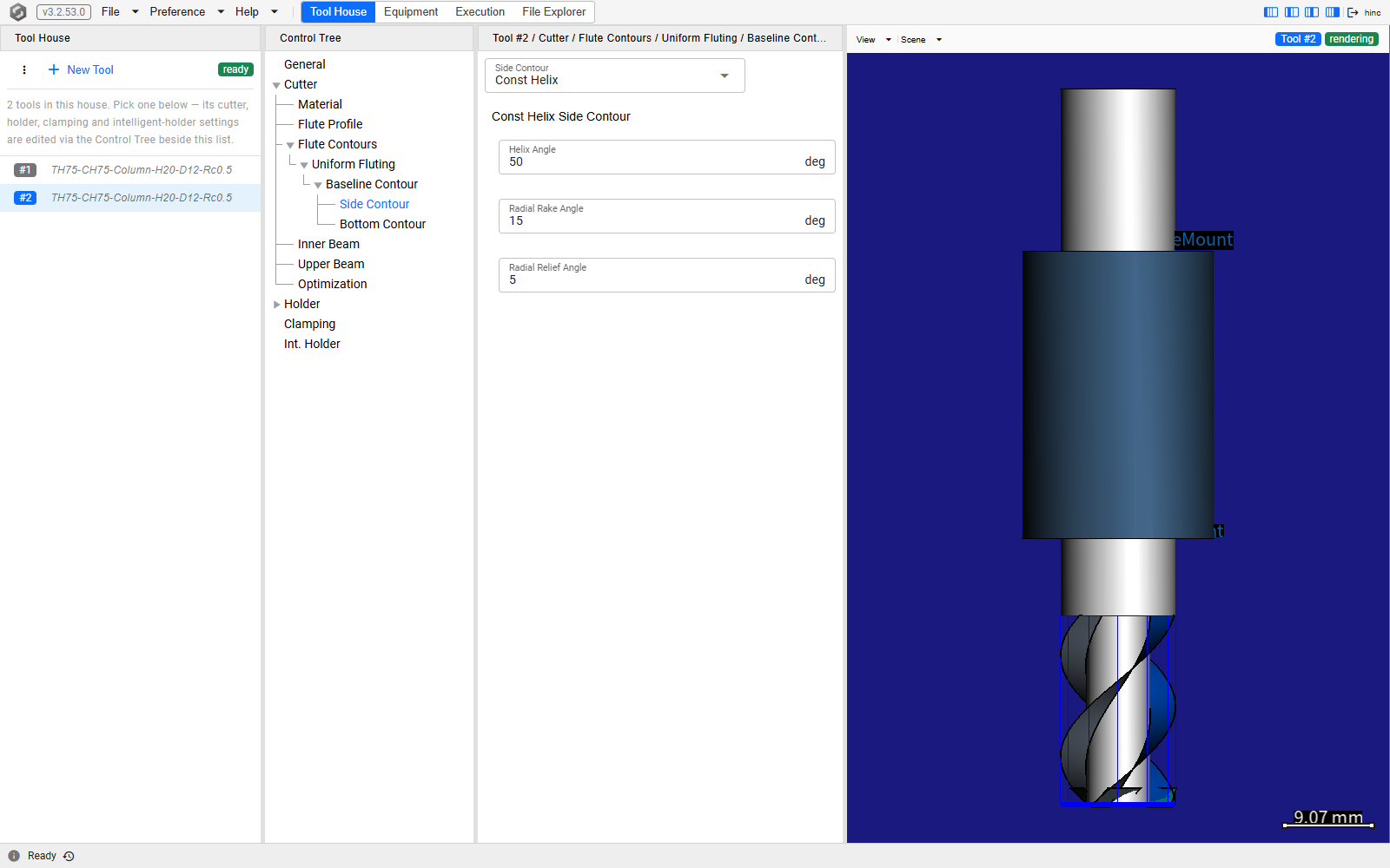
- Unfold Baseline Contour and select Side Contour. It is already a Const Helix edge, at 30°,
0° and 5°: enter Helix Angle
50and Radial Rake Angle15, and leave Radial Relief Angle at 5.
T2's Side Contour, at /tool-house/2/cutter/contours/fluting/baseline/side.
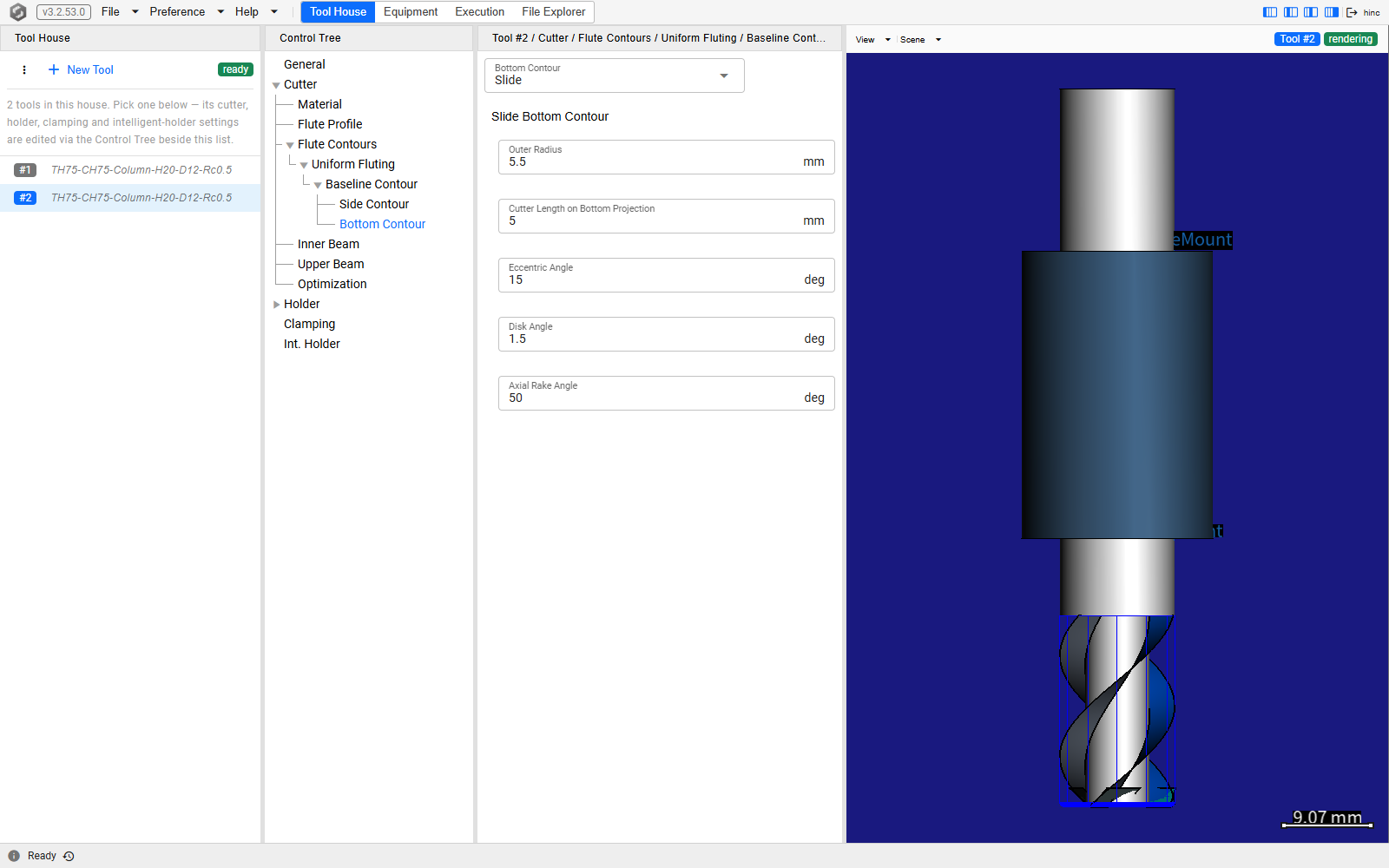
- Select Bottom Contour. It reads unset: set it to Slide. Eccentric Angle and Disk
Angle open at the sheet's 15 and 1.5; enter Outer Radius
5.5, Cutter Length on Bottom Projection5and Axial Rake Angle50.
A bottom edge matters where the tool cuts downward with a flat or concave bottom, as this bull-nose does; a drill needs none — Cutter Geometry says when to set one.
T2's Bottom Contour, at /tool-house/2/cutter/contours/fluting/baseline/bottom.
5. The core and the shank
- Select Inner Beam and leave it: Flute Dependent Ratio Profile sets the core's radius ratio from the flute count, and the node says so. Changing it is a lever for a cutter that breaks in the simulation and not in the shop — Cutter Adjustment Levers.
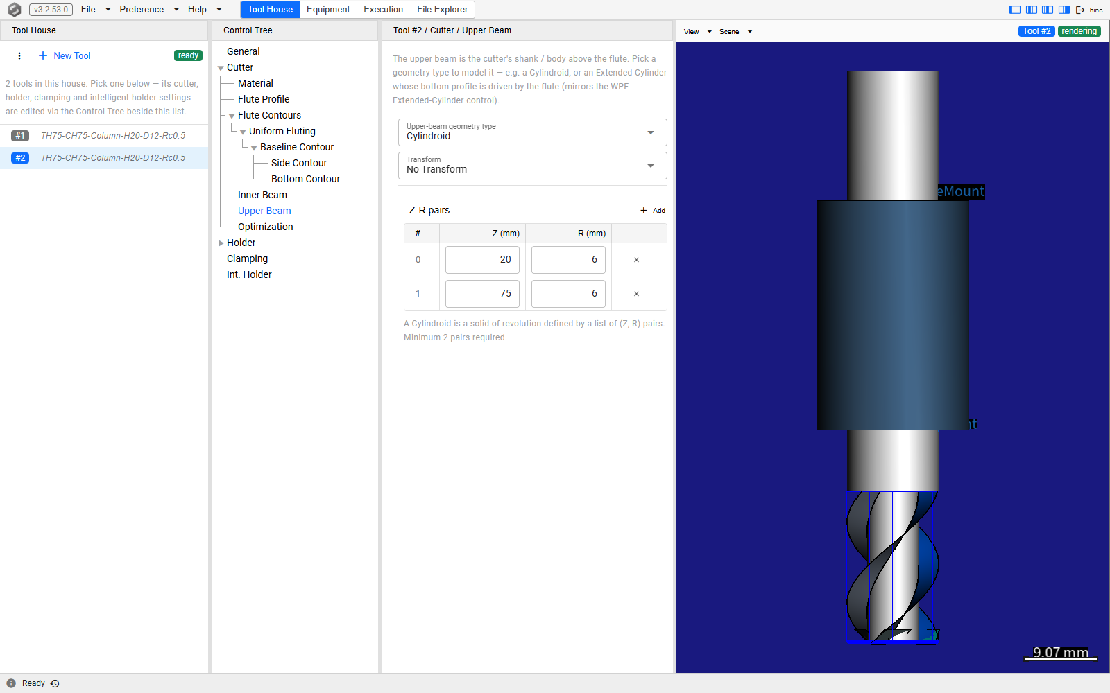
- Select Upper Beam and set Upper-beam geometry type to Cylindroid. Its Z-R pairs
table starts empty: press Add twice, then enter
20,6on the first row and75,6on the second.Zis measured from the tip, so the shank starts at the top of the 20 mm flutes and ends 75 mm up;Ris its radius.
T2's Upper Beam, at /tool-house/2/cutter/upper-beam.
6. The material, and the optimizer's limits
- Select Material. Under Flute Material, press Select beside the file field and choose Browse Resource….
- The picker opens on the library's
CutterMaterialfolder. TickWC-Co6-800nm.default.CutterMaterialand press Select. - Select Optimization. Enable Optimization is already ticked, and the limits it reveals are the defaults, the same as T1's.
T1's grade came inside its cutter file, with the same figures as this library file, so the two tools end up with one material. A solid-end cutter's shank is made of its flute material, so there is nothing more to set.
7. The holder
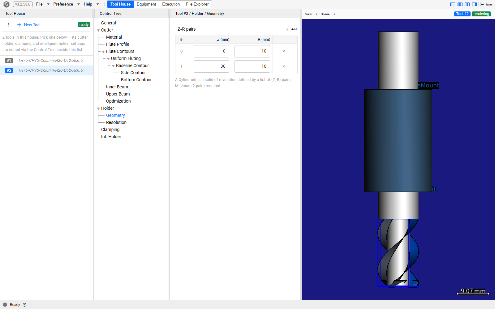
- Select Holder and set Holder Type to Cylindroid Holder. The node unfolds to Geometry and Resolution.
- Select Geometry. Its two rows are a placeholder —
40,3and80,3— so overwrite them with0,10and30,10: the holder's nose atZ = 0, 30 mm long, radius 10 mm. - Leave Resolution as it is.
T2's holder Geometry, at /tool-house/2/holder/geometry.
How a holder profile and the stick-out make up the tool's length is Cutter Geometry.
8. How far it stands out
- Select Clamping and enter Exposed Cutter Height
28. Preserved Distance follows to 8, the same length less the flute's 20. - Leave Setup Angle at 0, and Int. Holder as it is: both matter only for a smart holder — Smart Tool Holder.
9. Compare it with T1, and save
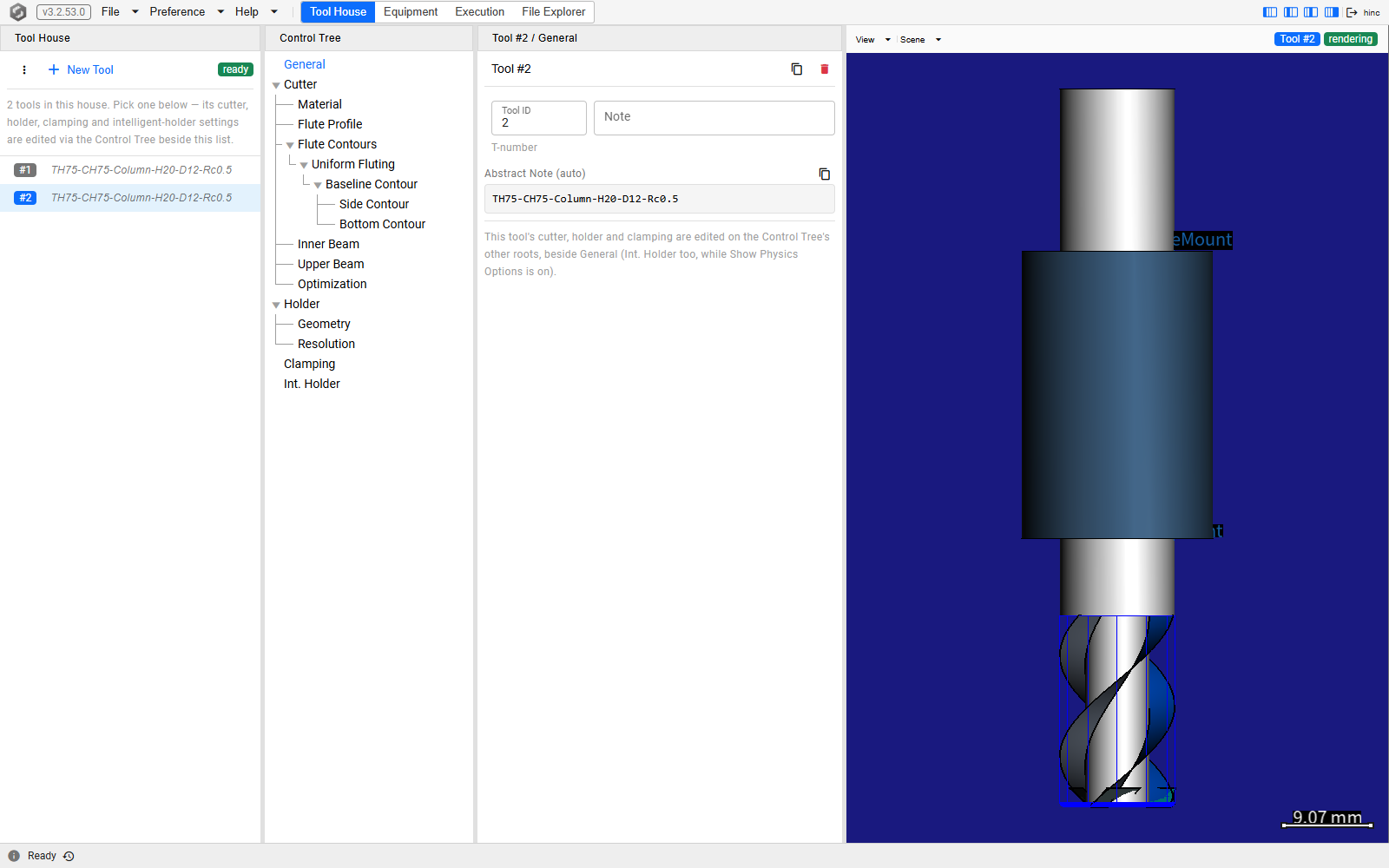
- Select T2's General. Abstract Note (auto) is built from the tool's shape.
- Select T1 in the list. The editor stays on General, and T1's abstract note reads the same.
- Walk down the tree with the two tools in turn — select a node, then T1, then T2 — and each node
shows the same values, down to the side and bottom contours. Material differs only in where
the grade is kept: T1's Flute Material field reads In the cutter itself (no file), where
T2's names the library file; the line under both reads
WC-Co6-800nm. - File › Save.
T2's General, at /tool-house/2/general.
10. Play the program on it
The program calls T01, so the new tool plays it once it takes T1's number:
- Select T1's General, press Delete and confirm.
- Select T2's General and change Tool ID to
1. - Press Execution, then Start.
The run takes the same 1,087 steps as T1 plays in Play the Project and Read the Result. File › ReLoad afterwards brings back the saved project, with both tools as they were in step 9.
Where to go next
- Cutter — every node of a tool's tree, including the kinds this tool did not use: an insert-end cutter, free fluting, a freeform holder.
- Cutter Geometry — what each quantity on the sheet means, and what to enter when a tool sheet leaves a value out.
- Cutter Adjustment Levers — which of these values to change when a simulated cutter behaves differently from the real one.