Smart Tool Holder
A smart tool holder is a machine tool accessory equipped with sensors that can monitor force and torque data in real time during machining. To ensure simulation accuracy, the following parameters must be configured correctly:
Sensor Configuration
Moment Arm Height
The simulated moments about the sensor are taken at one point on the tool axis, the tool's observation point. Everything compared against the holder's bending channels is evaluated there: the moment-about-sensor results of each step, the setup-angle estimate below, and coefficient training from holder recordings. Moving the point along the axis leaves the axial torque Mz unchanged and changes the bending moments Mx and My roughly in proportion to the arm. A wrong height is therefore a scaling error on the bending channels only, and nothing reports it.
The point is an anchor plus a height along the tool axis, positive toward the spindle. It is set on
the tool's Int. Holder node (Reference and Z Relative to Reference), which the Control
Tree shows while the Preference menu's Show Physics Options is on, or over the HTTP API with PUT /api/ToolHouse/{id}/observation and a body such as
{"reference": "HolderAnc", "relativeHeight_mm": 95}; a field left out keeps its current value.
| Reference | Anchor | Suits a sensor position given as |
|---|---|---|
HolderAnc — Holder Anchor |
the holder's nose, the end the cutter is clamped in (Z = 0 of a cylindroid holder profile); the spindle gauge line when the tool has no holder |
a distance above the holder nose |
ToolTip — Tool Tip |
the cutter tip | a distance above the tip, which changes whenever the cutter is re-clamped |
SpindleMountAnc — Spindle Mount |
the spindle gauge line, where the tool meets the machine | a distance from the gauge line; a sensor below it has a negative height |
None |
no point | nothing: the moments about the sensor are taken at an undefined height, so their bending components and magnitudes read NaN (the axial component still equals the torque about the tip) |
For a sensor built into the holder, HolderAnc is the natural reference. The gauge is fixed relative
to the holder nose, so the entered height survives a change of stick-out, and the arm from the tip
follows as stick-out plus height: a gauge 95 mm above the nose, on a cutter standing out 30 mm, is a
125 mm arm. Where the holder nose and the stick-out sit is set out in
Cutter Geometry.
A new tool starts at HolderAnc with a height of 0 — the holder nose, which is not where a strain
gauge sits. Left there, the example above is computed on a 30 mm arm instead of 125 mm, and the
simulated bending moments come out about four times too small.
The green observation ring the Equipment and Execution canvases draw at the observation point is
sized from the tool itself: it hugs the outer radius of the holder, the shank or the flute at that
height, a step counting as its wider side. It is drawn whenever the reference is not None and
Show Physics Options is on; the Tool House's own canvas does not draw it, and no calculation reads it.
Over the API the ring is part of the tool's own drawing: a MillingTool drawn whole, through
GetAnchoredDisplayeeList(API), draws it
whenever the reference is not None. To draw a tool without it, draw its Cutter and Holder
instead; do not set ObservationAnchorReference to None for that, which removes the point the
moments about the sensor are taken at (the None row above).
Holder Channels
Which of the three moment channels the holder delivers — Mx, My, Mz, one strain bridge each — is
declared on the tool's Int. Holder node (Holder Channels, three check boxes, all on for a new
tool; the node is shown while the Preference menu's Show Physics Options is on, as for the
observation point above), or with PUT /api/ToolHouse/{id}/observation and a body such as
{"channels": ["Mx", "My"]} — the whole set each time. The declaration says what the hardware has;
which channels an estimate or a training uses is that command's own selection — the Channel Mx / My / Mz
boxes of a Setup Angle Estimation command in the mission list, or the sample flags of a script call. A training or an estimate that selects
a channel the tool does not declare stops with Sample-Channel--NotObserved, naming the tool and the
channel, instead of reading a missing bridge as data. The declaration does not enter the physics.
What Mx, My and Mz Mean
The holder channels are the components of the moment M = r × F that the cut puts on the tool, taken about the observation point: F is the force the workpiece exerts on the tool, and r runs from the observation point (the centre of the gauge section, on the tool axis) to the point where F acts. The frame is fixed to the holder and turns with the spindle: Z runs along the tool axis from the tip toward the spindle, X is the holder's own radial reference, and Y = Z × X, 90° counter-clockwise from X looking from the spindle toward the tip. Each component follows the right-hand rule and is in N·m. Mx is the moment about the X axis, which a force along Y produces: it bends the tool in the Y–Z plane. A force along X shows in My, with a negative sign. Mz, the torque, is positive counter-clockwise seen from the spindle, the sign it has while an M03 spindle cuts.
A push gauge checks a holder against this definition in a few minutes, with the spindle stopped: push the tip toward +Y with a force F and the holder should read Mx = +F·L; push it toward +X and it should read My = −F·L, where L is the distance from the point pushed to the gauge section. A channel that answers the +X push with +F·L reports bending toward X, which is the moment about Y; map it as Mx = BendingY and My = −BendingX in a converted copy. On a two-flute cutter this check is the only safeguard: such a frame is a 90° rotation of the sensor axes, and the setup-angle estimator cannot tell it from a turned cutter.
Coordinate System Alignment
Basic Principle
- The cutting edge should be aligned with the sensor's X-axis
- Ensure the sensor XY coordinate system is consistent with the simulation XY coordinate system
- The impact of coordinate system misalignment is relatively smaller compared to the moment arm setting
Setup Angle Adjustment
- If perfect alignment is not possible, measure the offset angle — or let the software estimate it from a short recording, see Estimating the Setup Angle from a Recording; in the mission list that is the Setup Angle Estimation command, see Estimating Online, During the Play
- Enter the angle in the tool's Setup Angle field (Tool House → the tool → Clamping) — how far the cutter is turned in the holder about the tool axis
- The physics places every flute at the cutter's Flute Offset Angle, where the flute sits on the cutter body, plus this setup angle, so a cutter authored with a non-zero flute offset composes with what is entered here
- The setup angle is measured from the holder X axis to the cutter's angular reference, positive from X toward Y (counter-clockwise looking from the spindle toward the tip). For a square end mill with a zero flute offset the reference is the outer tip corner of flute 0, where the bottom and side edges meet. With a corner radius the reference sits at the inner end of the arc, and the outer corner lies a few degrees further on: 3.4° and 7.4° for a D8 cutter with a 0.5 mm corner radius at 25° and 45° helix.
- For a uniform fluting the deviation never exceeds half the flute pitch — 45° for four flutes, 60° for three, 90° for two — because turning the cutter by a whole pitch brings an identical edge onto the axis; a free fluting with unequal pitch has no such symmetry
Estimating the Setup Angle from a Recording
A ball end cutter has no edge that can be lined up against the sensor axis: the cutting edge curves along the helix into the axis, so the angle to enter is a guess. The angle can instead be estimated from the holder's own recording. Mounting the cutter turned by an angle does two things to the spindle-rotation-frame moments: every (Mx, My) sample rotates by that angle, and the waveform shifts along the rotation. The per-step phase search that coefficient training already performs absorbs the shift, and what remains is one rotation shared by every step. EstimateSetupAngle fits that rotation (together with a free scale — pinned on one channel of a one- or two-flute cutter, below) against the model built from a known cutting parameter, and reports it modulo the flute pitch — 90° for a four-flute cutter — with the diagnostics needed to trust it. An applied estimate advances the tool's Setup Angle on the Clamping node, for every fluting type alike; the cutter's flute contours are left exactly as they were authored.
EstimateSetupAngle(Mx|My, "Output/setup-angle.json");        // estimate and report
EstimateSetupAngle(Mx|My, "Output/setup-angle.json", true);  // ... and apply it to the tool
ResetRuntime();                                                 // the physics session snapshots the flute geometry: reset before replaying
The recording is mapped onto the steps like any training data (see Force Training); the estimate reads the mapped bending moments. What the sampled cut must give:
- Intermittent contact. A flute entering and leaving the material within each revolution is what makes the angle visible. A full-immersion pass with several flutes engaged at once nearly cancels it: the summed force barely changes over a turn, the holder sees a vector that merely rotates, and a rotation is then indistinguishable from a time shift. More flutes and more simultaneous contact make the estimate harder; the estimate reports this as a low
Contrastand warns. Light side cuts and thin-wall crossings, as in Smart Holder Training, are the right kind of cut. - The transverse channels the holder has. Mx and My together is the normal case. A cutter with three or more flutes can be estimated from one of them (
EstimateSetupAngle(Mx, ...)): over a turn one channel sees the whole transverse moment from N directions, the fit then solves its two unknowns from that channel, reportsSetupAngle-Channel--Single, skips the mirror check, and needs the channel's sign and axis to be right. A one- or two-flute cutter's holder-frame moment swings along one line, so one channel reads only its projection on that channel, and a turned cutter would read the same as a lower gain if the magnitude were free. It is not: the holder delivers calibrated N·m and the coefficients have fixed units, so the estimate pins the scale and reads the angle from the projection — to 1 as assumed, or, when Mz is selected too, to the ratio the torque measures: Mz = R·Ft reads the tangential force's size whatever the setup angle, so the measured-over-model torque is the recording's magnitude against the model's, and the angle then no longer rests on the coefficients' absolute magnitude or the bending calibration, only on the observation height against the effective radius (L·F against R·Ft), the torque-to-bending ratio of each, and the pulses as sampled, though by less than with the scale assumed: the torque's zero is read from the samples between the flutes' pulses and the ratio keeps the torque's undistorted mean, so its sampling loss nearly matches the bending's and mostly cancels (a cut that leaves no gap wide enough in the turn — a full slot or nearly so — falls back to the slope with an intercept, which keeps only the torque's harmonics, and those lose more to the sampling than the bending's fundamental; the report'sNotesays which and prints the zero) (ScaleRatioreports that ratio; NaN when the scale was assumed; a torque that gives no usable ratio — a dead bridge, or one too noisy to follow the model's torque — keeps 1 and says so,SetupAngle-Scale--MzNotUsable). Two angles give the same projection — symmetric about the rotation that lays the model's moment line on the channel, they put that line at mirror positions about the channel axis — and the estimate reports both,SetupAngle-Channel--SingleFixedScale: one is the setup angle, the other its mirror image, and only the model moment's share off its line (the helix sweeping the direction within a pulse;ModelIsotropy, 0.004 on the site's two cutters) prefers one — a preference that flipped on the engine's own recording, where the pulses as sampled distort the shape more than that share does, so the objective ratio is no basis to choose. Take the one the mechanical alignment agrees with: with the truth near 0° the mirror lies near −2α, where α is the direction of the model moment at setup angle 0 — tens of degrees away. In a deep helical cut that share rules the mirror out and one angle is reported (SetupAngle-Channel--SingleFixedScaleUnique); a channel reading nearly nothing (the moment runs across it) also gives one angle, but a dead bridge reads the same and the warning says so (SetupAngle-Channel--SingleLowSignal). The reading is only as good as the pinned scale. With the scale assumed 1 (Mx or My alone, or an Mz that gave no usable ratio) each 1 % of error in the coefficients, the observation height, the holder's calibration or the pulses as sampled (about 50 samples a turn read them 2–3 % low) moves it by about 1° (MagnitudeSensitivity_degin the report), so the parameter must be this cutter's own, trained on a dynamometer; a library parameter from another cutter, tens of percent off in magnitude, moves it by tens of degrees. With the scale from Mz a magnitude error the torque and the bending share cancels, and the coefficients' torque-to-bending ratio still counts. A channel that reads more than the model can give along its line fits no angle —SetupAngle-Scale--RecordingAboveModel, the reading is pulled onto that line and is no measurement. The gate never applies such an estimate by itself when it has two candidates, when the channel reads more than the model, or when it reads nearly nothing; the online refusal then names the setup angle each candidate would make. When both are selected and one reads almost nothing against the other after the steps are folded onto one turn,SetupAngle-Channel--LowSignal(three or more flutes) orSetupAngle-Channel--LowSignalFewFlutes(one or two, where the text explains that a live channel can also sit near zero) says which — a warning: the estimator never drops a channel you selected. Mz is optional: it enters the per-step phase choice, the energy diagnostics and, on one channel of a one- or two-flute cutter, the pinned scale — not the angle's equation itself. - Early in the cutter's life. Each mounting is estimated once; sample the first cutting after mounting, before wear moves the cutting forces away from the parameter. Prefer several windows of about a second over single entry or exit events, whose transients are not stable.
- A parameter that does not depend on this holder. The angle and the parameter's force direction enter the holder data as one combined rotation. A parameter trained from this very holder at an unknown setup angle has already absorbed the angle into its coefficients and would estimate zero; use a dynamometer-trained or library parameter, or one trained with the angle known, and do not retrain that parameter after applying an angle estimated against it.
Reading the report: Angle_deg is the rotation to add to the tool's current setup angle, folded into the flute period; Contrast below about 0.01 means the cut does not constrain the angle; Scatter_deg is the spread of the per-step angles; ScaleRatio near 1 confirms the parameter magnitude and the moment arm; MirrorPreferred says the sensor axes look swapped or negated rather than rotated — check the holder's axis mapping before applying anything (this check is not evaluated for two-flute cutters, whose waveform is nearly its own mirror image). TransverseChannels names the channels the angle was fit on; ModelIsotropy is 1 when the model moment covers every direction over a turn and 0 when it runs along one line (a two-flute cutter, where one channel cannot separate the rotation from the gain); TransverseEnergyRatio is the synchronous energy of My over Mx after the used steps are folded onto one turn (NaN with one channel); LowSignalChannel is the channel the low-signal warning named, null when none. The four are members of the report entries (SetupAngleReport); the first three also appear in the SetupAngle--Estimated message, and the weak channel is named by the SetupAngle-Channel--LowSignal / --LowSignalFewFlutes warning. ScaleFixed is true when the scale was pinned (one channel on a one- or two-flute cutter; ScaleRatio is then the torque-measured ratio when Mz was selected, NaN when the scale was assumed 1 — also when a selected Mz gave no usable ratio, a dead bridge or one that does not follow the model's torque, which the SetupAngle-Scale--MzNotUsable warning says): AlternativeAngle_deg is the mirrored candidate (NaN when there is none), AlternativeObjectiveRatio how much worse it fits (near 1: the data cannot choose), ChannelToModelRatio the channel's amplitude over the model moment's along its line (1 or more: no angle fits; below 0.03: nearly nothing read), and MagnitudeSensitivity_deg the degrees the angle moves per 1 % of magnitude error.
Estimating Online, During the Play
A cutter is detected once per mounting, from the first seconds it cuts — nothing on site records the angle later. The estimate can therefore run by itself while the program plays, and the mission list is where it is set up: Add Command → Measurement → Setup Angle Estimation, placed before the program it watches. Its panel is the generic field editor:
| Field | Meaning |
|---|---|
| Timing | During The Play arms the estimation when the command runs — the play then estimates at the player's next pace point once the contact window is complete; Now estimates at once on the steps built so far (place the command after the program for that) |
| Tool Id (-1: the first tool that cuts) | the tool-house id of the cutter, or −1 for the first tool that cuts: under During The Play the first tool to touch the workpiece after the command runs (the mounted tool when it runs mid-play); under Now the first tool that touched the strip from its first step — name the tool when an earlier program of the mission cut with another one |
| Contact Seconds | the contact time to sample — the tool's touched steps from its first cut until their durations sum to this |
| Recording File | the holder recording, relative to the project folder |
| Channel Mx / My / Mz | the channels the estimate reads — the same selection as the sampleFlags of the script forms below; Mx and My on by default, Mz off; with none ticked the tool is estimated on the channels its Int. Holder node declares. A box ticked for a channel that node does not declare is refused as Sample-Channel--NotObserved |
| Apply To Tool | advance the tool's setup angle by the estimate and recompute the finished steps; off only reports |
| Outlier Ratio | the fraction of the worst-fitting steps trimmed before the final estimate |
| Known Cutting Parameter File | a parameter file to build the model from instead of the workpiece's; blank uses the workpiece's |
| Report File (JSON) | an optional report file; blank writes none — the result is read back from the API below either way |
The row reads back what it will do — Setup Angle Estimation [During The Play · T1 · 30 s · Record/holder.csv] — and the project file keeps every field. A command without a recording reports SetupAngle-Command--NoRecording and arms nothing; a fault reports SetupAngle-Command--Fault and the run goes on. The same from a script (a script line in the mission list, or the console), naming the tool, the contact time to sample and the holder recording:
ArmSetupAngleEstimation(1, 30, "Record/holder.csv");                                     // tool 1: its first 30 s of contact
ArmSetupAngleEstimation(-1, 30, "Record/holder.csv", true, "Output/setup-angle.json");   // the tool that cuts next, with a JSON report
ArmSetupAngleEstimation(1, 30, "Record/holder.csv", sampleFlags: Mx);                    // a holder with one transverse bridge
Both script forms take the channels as a trailing sampleFlags argument — Mx|My by default, Mx or My alone for a holder with one transverse bridge (on a one- or two-flute cutter read with the scale pinned, as above), Mz optional, as for EstimateSetupAngle above — written as a named argument, since it follows the optional report and parameter arguments; the request form (SetupAngleOnlineRequest) carries it as SampleFlags.
Contact time counts the tool's touched steps only, from its first cut after the arm; a tool change inside the window does not end it. When the window is complete the player thread, at its next pace point — so nothing runs concurrently with the play, and a paused play stays paused — maps the recording onto exactly those steps, estimates the setup angle on them, and, unless the gate refuses, advances the tool's setup angle by the estimate and recomputes every step built so far from its stored engagement (RecomputeStepPhysics). The play then continues on the new angle, so the finished strip carries one angle from the tool's first cut. The gate refuses — and only reports — when Contrast is below 0.01, Scatter_deg above 10°, the mirror hypothesis is preferred, or the estimate read one channel of a one- or two-flute cutter and has two candidates (SetupAngle-Online--RefusedFixedScale names the setup angle each would make: enter the one the mechanical alignment agrees with on the tool's Clamping node); the report says which. An estimate that lands within MinDeltaToApply_deg of the angle the tool already carries — 0.5° by default, folded into the flute period — is reported as --NegligibleDelta and neither written nor recomputed, so a second estimate on an already-corrected tool does not rerun the force kernel for nothing. The explicit form does the same on the steps built so far — after the play command in the mission list, or from the console once the play has ended:
EstimateSetupAngleByFirstContact(1, 30, "Record/holder.csv"); // the same window, estimate, gate, application and recompute — now
The recording: for a CSV play, the played file itself (controller and holder columns in one file) or a shot file written beside it — the steps carry the controller's wall clock and the rows are paired by it. For an NC play there is no wall clock, so the file's Time column is read as the play's own timecode; the shot file of a replay of the same program at the same resolution then lands exactly on the steps that produced it, which is the simulation-side check of the whole chain. The file is re-read at the trigger, so a recording still being written is seen up to date. Messages: SetupAngle-Online--Armed, --Triggered and --Done trace the normal path; --Refused names the gate; --NegligibleDelta says the estimate was too small to be worth applying; --NotReached says the run ended before the window was complete; --NoPlayerRun says the play is not on the player (a direct PlayNcFile request) — use the explicit form after it; --Busy refuses the explicit form asked from the console while a run holds the player — wait for the run to end, or put the call in the mission list, where it is already on the player thread; --AppliedNotRecomputed is the warning that matters — the angle reached the tool but the recompute did not run, so the finished steps are still on the old angle and the program has to be replayed after ResetRuntime().
Reading the result. GET api/Execution/last-setup-angle-estimate returns the last estimation of the open project, the angle first. online is the last online run — armed or Now, even one that was refused before it estimated (--Busy, --NoContact, --NoMapping …): the request (tool, window, recording, channels), the sampled window, the estimate with the gate's verdict as that run judged it (applicable, or the refusal), what was applied (appliedDelta_deg) and the recompute's outcome. tools holds the last estimate that actually ran — the online run's, or a script's EstimateSetupAngle — one entry per estimated tool with the tool's setup angle as it now stands (setupAngle_deg), the estimate (estimate_deg, folded into period_deg; with scaleFixed, one channel of a one- or two-flute cutter, the other candidate as alternativeEstimate_deg), the verdict of the default gate and the report entry (SetupAngleReport) without its per-step rows and its objective curve; ?full=true adds those. The two halves can come from different runs — an armed estimate followed by a Now command on an empty strip leaves the refused run in online and the earlier estimate in tools — so each tools entry says with fromOnlineRun whether it is the estimate online was made from. Opening another project clears both. The same facts reach the Shell messages (SetupAngle-Online--Done names the applied angle, the contrast and the scatter), and the applied angle shows on the tool's Clamping node as its Setup Angle.
What the application does to the strip, and what it costs, is the subject of Recomputing a Finished Strip: a setup-angle change — like a change to the cutter's flute offset angle — reruns the force kernel on the tool's touched steps, which consumes milling-force licence steps.
Factors Affecting Accuracy
Coordinate Transformation Effects
- A setup angle offset rotates the measured (Mx, My) pair. The resultant |M| does not change, but a single channel can read anything from 0 to |M| — the same 45° offset takes Mx to √2 times its aligned value one way and to zero the other way
- This difference is inherently a result of coordinate transformation, not a measurement accuracy issue
- Even with the same smart tool holder, different setup angles will produce different measurement data
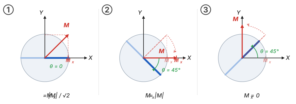 ① — the cutting edge (blue) lies on the sensor X axis, θ = 0; in this example the transverse
moment M the cut produces sits at 45°, so Mx = My = |M|/√2. ② — the same cutter mounted with its
edge 45° clockwise of the X axis. Nothing about the cut has changed, so M is carried round with
the edge and lands on the X axis: Mx′ = |M|, √2 times the value in ①, and My′ = 0. ③ — the same
45° the other way puts M on the Y axis, and Mx′ = 0. In general Mx′ = |M| · cos(angle between M
and the sensor X axis): the resultant never changes, and one channel on its own can read anything
between 0 and |M| — a coordinate effect, not a measurement error. Entering θ as the tool's
Setup Angle lets the simulation report in the sensor's own frame.
Best Practices
- Prioritize accurate moment arm height configuration
- Align the cutting edge with the sensor X-axis as closely as possible
- If perfect alignment is not achievable, always measure and set the correct setup angle
Only with these parameters correctly configured will the simulated micro-waveforms match the actual sensor measurements.
See Also
- Smart Holder Training — the cut shapes and conditions that turn a correctly configured holder into trained milling coefficients
- Milling Physics Coordinates — the frame the holder's forces and torques are reported in
- Cutter — where the holder's settings are entered in the application
- Cutter Geometry — the holder nose and the stick-out the observation height is counted from
- Recomputing a Finished Strip — what an applied setup-angle estimate re-derives on the steps already built, and what it costs in licence steps
- The Other Commands — the Setup Angle Estimation command that runs the estimate from a mission, and the boxes on its panel