Cutter Geometry
How a cutting tool is described to the simulation: what kind of tool it is, how its cutting envelope is expressed, and the individual quantities the force, wear and thermal models read off it. Every value here is a property of the tool rather than of a cut, so it is entered once per tool and reused by every step that tool takes.
Ordered from the classification, through the two ways an envelope is expressed, to the quantities that hang off it.
Cutter Body Types
Cutter body types include:
- Milling Any tool that machines by rotation is classified as milling in HiNC, including drilling and boring.
- Freeform Subtraction Cutting tools, EDM (electrical discharge machining) dies.
Milling Tool Description Parameters
- Material: Shank material, cutter body material, (multi-layer) coating material and thickness.
- Cutting edge rotation envelope: Can use simplified parameters (APT) or a custom ZR table.
- Simplified (yield-equivalent) edge center rotation envelope:
- Solid space ratio of the cutting edge rotation envelope.
- Custom ZR table.
- Clamping end (non-cutting zone) shape: Custom ZR table.
- Per-tooth geometry (including side edges and bottom edges):
- Simplified parameters: Helix angle position, rake angle, relief angle.
- Custom per-Z value: Helix angle position, rake angle, relief angle, radius length.
- Hone radius, tool weight, insert weight, and (thermal-equivalent) thickness.
For information on measuring rake angle and relief angle, refer to Radial Angle Measurement.
APT — the Simplified Edge Envelope
APT (Automatically Programmed Tool) is a universal tool definition, and the simplified alternative to a custom ZR table for the cutting-edge rotation envelope. Refer to the APT parameter diagram:
Note
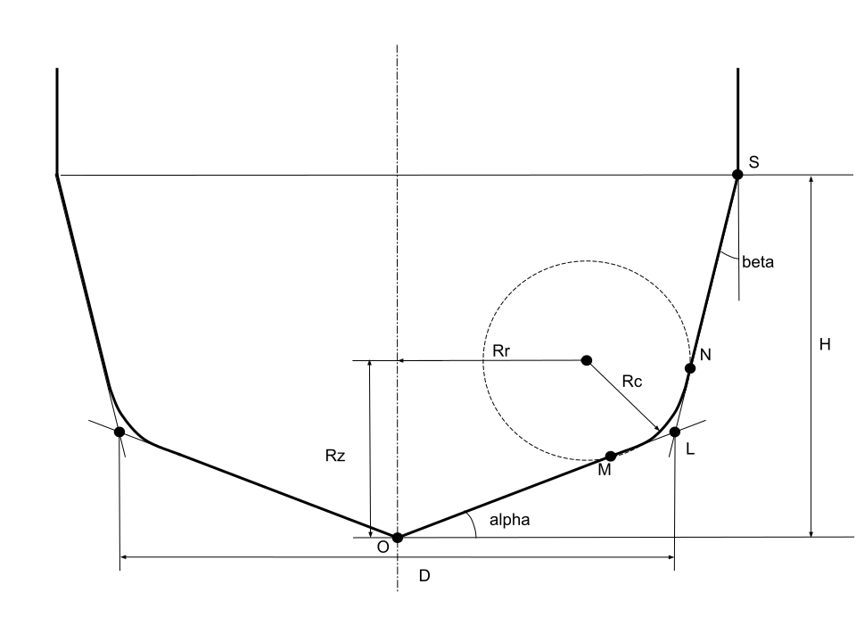
APT parameter description:
D: DiameterRc: Corner radiusRr: Distance from corner center to tool centerlineRz: Distance from corner center to tool tip horizontal planeAlpha: Angle between horizontal plane and tool tip cone surfaceBeta: Angle between tool centerline and tool wall cone surface
Upper Beam (Clamping End / Shank) Geometry
The upper beam is the cutter's shank / body above the flute — the non-cutting, clamping zone. It can be modeled with several geometry types; the two common choices are:
Cylindroid — an explicit ZR table. You author every
(Z, r)pair, so the shank radius (and any stepped / necked profile) is whatever you type in. This faithfully reproduces a known shank, but every value is data you must supply.Extended Cylinder — a cylinder whose start (bottom) profile is driven by the flute and whose only parameter is the total length. Its radius follows the cutter (flute-top) radius automatically, so it needs no shank measurements — only a length long enough to reach the holder.
⚠
FullLengthis the beam's FULL length measured fromZ=0(the cutter tip), so it includes the flute span — it is not the remaining segment from the flute top to the exposed end. It must therefore be larger than the flute height: e.g. flute height 20 mm and 10 mm of shank above it →FullLength = 30, not 10. A value at or below the flute height inverts the beam solid; thermal physics then cannot build its shank shell layers and reports aCutter-UpperBeam--ExtendedCylinderFullLengthTooShortconfiguration error at tool change (the web editor rejects such a value outright).
Convention — prefer the Extended Cylinder when the shank is not given. Most tool sheets (especially at quoting stage) list only the cutting diameter, corner radius, and stick-out; they do not give a shank diameter or a stepped/necked profile. In that case use the Extended Cylinder: it extends the flute by a length without inventing a radius the data does not support. A hand-authored Cylindroid here would bake a guessed shank radius into the model — and an over-fat guess produces false clearance / collision results, while an over-thin one understates the body. Reserve the Cylindroid (explicit ZR) for tools whose shank or neck profile is actually known or measured — e.g. stepped, necked, or back-tapered shanks where a flute-radius extension would be wrong.
Tip: because the Extended Cylinder's radius tracks the flute, set its length comfortably past the exposed cutter height so the beam reaches into the holder with no gap; the overlap is harmless for clearance checks.
Relief Angle Setting
The relief angle setting in HiNC refers to the primary relief angle. It is used to calculate flank wear width (Flank Wear, VB).
Cutter Body Weight
Cutter body weight is used for thermal transfer calculations.
- Solid tools: Enter the weight of the solid tool as the cutter body weight.
- Indexable tools: Enter the total insert weight as the cutter body weight, excluding the weight of the tool body.
Hone Radius
The hone radius represents the sharpness of the tool and is the radius at the cutting edge tip. Typical values range from 20 to 50 um.
Tools used for machining easy-to-cut materials typically have a smaller hone radius (e.g., Al6061-T6, which can be assumed as 20 um); tools used for difficult-to-cut materials typically have a larger hone radius (e.g., stainless steel, which can be assumed as 50 um).
Edge Profile and Edge Grind — Bottom Edge Grind
The bottom edge grind needs to be configured when the bottom edge is horizontal or concave, and it affects segments with downward cutting.
Drill bits do not require bottom edge grind configuration — only the side edge grind needs to be set. This is because drill bit bottoms are not horizontal or concave. If a custom drill bit has a horizontal or concave bottom, then the bottom edge grind must be configured.
Typically, only bull-nose cutters require bottom edge grind configuration. Note that flat end mills usually do not perform downward cutting and should not, but if the process does so, the bottom edge grind must be configured.
Insert Cutters — a Worked ZR Table
Insert cutters can be modeled in the virtual environment. See the examples below.
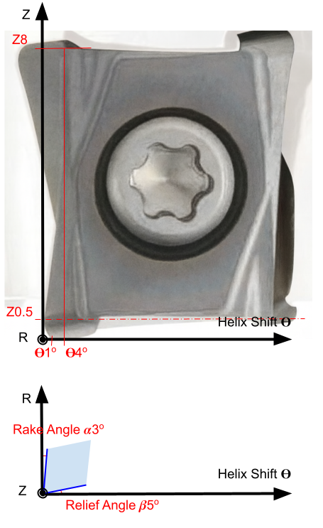
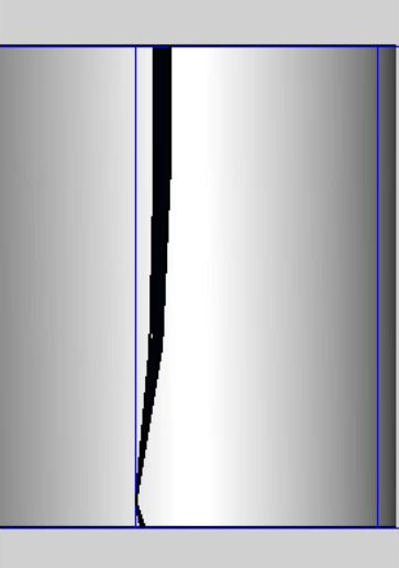
| Z | R | S.Ang. | R.Ang. |
|---|---|---|---|
| 0 | 8 | 1 | 3 |
| 0.2 | 8 | 0.5 | 3 |
| 0.4 | 8 | 0 | 3 |
| 0.5 | 8 | 0 | 3 |
| 3 | 8 | 3 | 3 |
| 6 | 8 | 4 | 3 |
| 8 | 8 | 4 | 3 |
See Also
- Radial Angle Measurement — how to measure the rake and relief angles entered here
- Designing a Training Cut Set — why the helix angle entered here decides whether a training run can recover the shear coefficients
- Cutter-Location (CL) Playback — a CL file's
TLDATAfeeds this same tool-geometry model - Cutter Adjustment Levers — the three of these quantities a process engineer can actually move to cut a force peak
- Cutter — where a tool carrying this geometry is created and edited in the application