Smart Tool Holder Coefficient Training
By cutting the following shapes and collecting three-direction torques with a smart tool holder, you can train milling coefficients through HiNC projects.
Overview
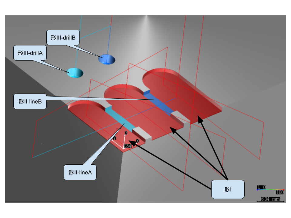
- T1 End mill D10 4 flutes
- T2 Drill bit, diameter unrestricted
Click to download NC code.
Important
What this set determines, and what it does not. Both Shape II passes run T1, so the milling passes span two feeds per tooth — 0.1 and 0.05 — at a single helix angle. That is a spread in the right variable, and a narrow one: it works on the slope–intercept collinearity between the shear and the ploughing coefficients. Nothing in the set works on the other degeneracy, the bending-moment plane null: one combination of the edge and normal shear coefficients stays unobservable, and a set of symmetric four-flute passes carries no cutter phase of its own. Which way the run then fails depends on the channels measured — with the axial torque channel present (IsMzEnabled, see Force Training) the fit converges and reports a high correlation over shear values orders of magnitude too large; without it the fit collapses rather than degrading. Repeating Shape II with an end mill of a clearly different helix angle removes the plane null, but does not on its own make the set determined — a wider chip-load range across the passes is the other half. See Designing a Training Cut Set.
Note
Adjusting Machining Method
- Speed and feed can be changed according to material conditions, but feed per tooth must be in multiples.
- Slower spindle speed allows the smart tool holder to collect more data per unit time.
- The wall thickness between the two slots in Shape I needs to be thin enough so that Shape II cutting is discontinuous per revolution.
Shape I
Shape I consists of three red slots, which are preparatory shapes, no need to collect smart tool holder data.
- ae10; ap1; S1500; F600
Shape II
Shape II penetrates through the thin walls between the three red slots, need to collect smart tool holder data.
- lineA: T1; ap1; S50; F20 (frt0.1)
- lineB: T1; ap1; S50; F10 (frt0.05)
Shape III
Shape III is drilling, need to collect smart tool holder data.
- drillA: T2; dp4; S50; F20
- drillB: T2; dp4; S50; F10
See Also
- Designing a Training Cut Set — what a set of passes has to span before the coefficients are recoverable at all
- Smart Tool Holder — the moment arm and installation angle a training run assumes are already right
- CAM Floating-Point Drift — a measurement error source to rule out before trusting a training run
- Milling Physics Coordinates — the spindle-rotation frame the holder's torques are reported in