Program Zero Alignment
Program zero is the point an NC program treats as X0 Y0 Z0. The machine finds it by adding a work
offset — G54, G55 and the rest — to machine zero, so a simulation only cuts where the real machine
cuts if the program zero on the model and the work offset in the controller agree. Making them agree
is this task, and it runs in one of two directions depending on why the simulation is being built.
Which direction to align
| You are | Align | Because |
|---|---|---|
| Planning a job from an NC file, before the part is set up on the machine | the work offset onto program zero | The workpiece and fixture can sit wherever is convenient; the offset has probably not been measured yet, and the model does not have to match a real table |
| Reproducing a cut from a controller log, a machine-coordinate feed, or a job already running | program zero onto the work offset | The recorded data is in absolute machine coordinates, so the part has to sit where it really sits, or collisions, overcut and engagement will not match what happened |
Both directions need the workpiece already placed on the fixture and the fixture on the table — that is Anchor, and it comes first.
Where program zero sits on the workpiece
Geom To Program Zero (/general-setup?tree=equipment/workpiece/anchor/geom-to-program-zero)
holds the offset from the workpiece geometry to program zero. Set it to whatever point the NC
program was written around: for most milling programs that is a corner or the centre of the stock's
top face. Nothing else on this page makes sense until that point is where the programmer put it.
Planning: write the offset from where the workpiece is
The Controller branch's Work Coordinates leaf
(/general-setup?tree=equipment/controller/program-data/work-coordinates) holds the table the run
resolves G54 against, one row per coordinate id.
- Place the workpiece and fixture wherever the scene is convenient to work in.
- Select the Work Coordinates leaf and find the row the program uses —
G54for most programs. - Press P0 in that row. It writes the machine coordinate the workpiece's program-zero anchor is currently sitting at into the row, which is exactly the number the machine's operator would key in after touching off. M0 beside it writes machine zero instead, which is how a row is returned to no offset at all.
The leaf on a demo project, at
/general-setup?tree=equipment/controller/program-data/work-coordinates. The grey line above the
table names where this brand keeps the offsets — on Fanuc, its own parameter table — and the rows
below it are the coordinate ids that brand holds, with only G54 carrying a value here. The panel
is narrow, so the row actions sit off the right edge.
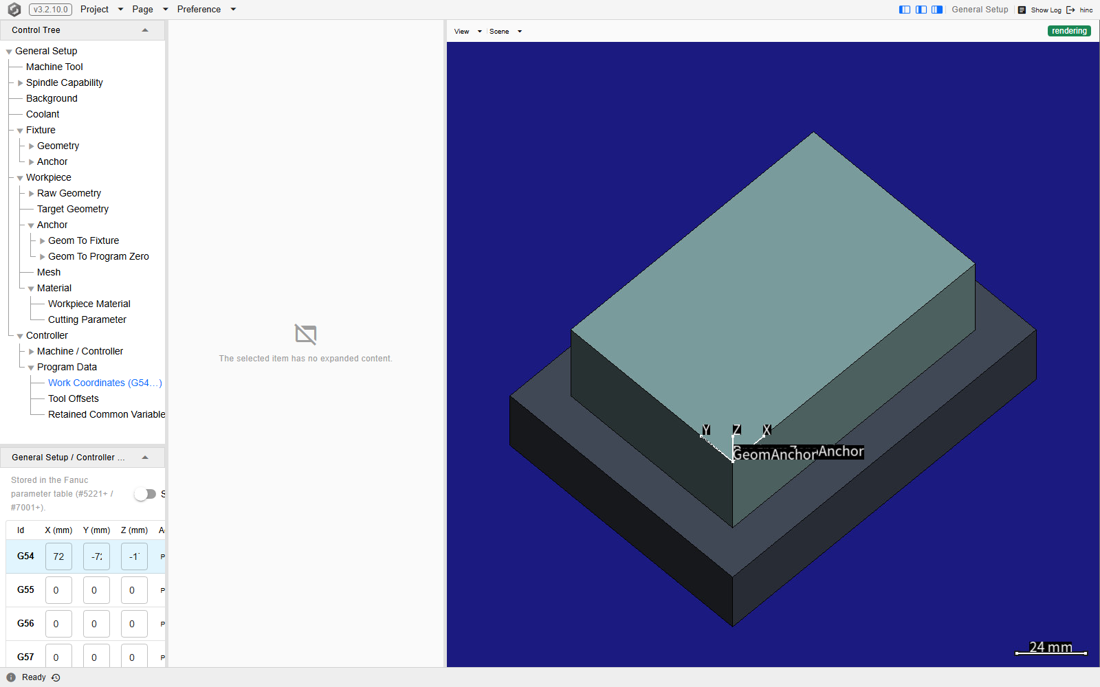
P0 has something to write only once the scene is assembled. It works out where the program-zero anchor is by walking the machine chain to it, so a project with no machine tool attached, or a workpiece that has not been placed, gives it nothing to compute and it reports that it could not get the machine position at program zero rather than writing a wrong number.
The row's values can also be typed in directly when the offset is already known from the machine. Clicking anywhere in a row marks that coordinate on the canvas, so the offset can be seen rather than only read.
Reproducing a real cut: place the workpiece on the offset
Going the other way — leaving the offset alone and moving the part to meet it — is not offered on the runner path. The Legacy-Controller screen that used to carry a one-press control for it (Align P0) was removed on 2026-09-11, and the Work Coordinates leaf's two row actions both write the row — P0 from where program zero sits, M0 to machine zero — and neither moves the part. So in the reproducing direction the part is placed by hand, and the row checks the placement rather than making it:
- Type the recorded offset into the row the program uses — the values can be entered directly, as above — and click the row so the canvas marks that coordinate.
- Move the part to meet the mark by changing where the fixture sits on the machine table: the fixture's Geom To Table transform, in Anchor. The workpiece rides on the fixture, so its program-zero anchor moves with it.
- Once the program-zero anchor sits on the mark, the part sits where it really sat. Pressing P0 afterwards rewrites the row from the scene, so use it only as a check: the numbers it writes should be the ones you typed, and any difference is how far the placement is off. If they differ, fix the placement and type the recorded offset back in — the run resolves against whatever the row holds, and P0 has just overwritten it.
Checking that it worked
A wrong alignment — a wrong offset, or a workpiece at the wrong height — shows up as overcut, collision or nocut, and it shows up early: usually within the first hundred or so NC lines. Check it cheaply before committing to a full run.
- Set a coarse Initial Resolution on the workpiece's Mesh item — around an eighth of the cutter diameter is enough to see gross errors, and it runs quickly. That is Workpiece.
- Run, and watch the opening Z plunge. This is where a wrong offset shows first.
Tip
If the tool plunges far deeper than the programmed depth and the holder gouges the stock, the work offset's Z is almost certainly wrong — the workpiece is modelled higher or lower than it really sits.
One false positive is worth knowing: a roughing cut with a spiral entrance into tough material can legitimately exceed the modelled cutting conditions while the setup is perfectly correct. It is uncommon, and early overcut, collision or nocut usually does mean the alignment is wrong.
When the planned offset is not the real one
In the reproducing direction, the offset aligned to must be the offset the machine was actually using, not the one the job was planned with. Operators re-zero between setups — after a manual tool change, after re-cutting stock — so a planned G54 and the real one can differ by an amount that cannot be assumed in advance.
When the data comes from a controller log, derive the offset from the log's own machine coordinates rather than trusting the plan: an invariant that survives an operator's edits — a known cutting depth, the span of a feature — mapped onto the recorded coordinates recovers the real offset on those axes. Axes the operator may have shifted with nothing to key on are not recoverable this way. A wrong Z is the one that bites hardest, because it places the workpiece away from its true height and the tool over- or under-plunges from the first block.
A placement convention that makes this easier
The three transforms that hold the assembly together can be put anywhere, but a block-on-plate setup is easiest to reason about when each sits at the middle of the face it meets:
| Transform | A good default |
|---|---|
| Fixture's Geom To Workpiece | The top centre of the fixture geometry |
| Workpiece's Geom To Fixture | The bottom centre of the workpiece geometry |
| Workpiece's Geom To Program Zero | The top centre of the workpiece geometry, or whichever top point the program was written around |
Nothing above depends on this convention — P0 walks the assembly as it stands, whatever the transforms hold — but a scene built this way is far easier to check by eye, and far easier to place by hand in the reproducing direction.
See Also
- Anchor — placing the workpiece, fixture and tool relative to the machine, which comes before this
- Assembly Anchors — the named buckle anchors this alignment resolves against
- Workpiece — the branch carrying the Geom To Program Zero transform this task sets, and the Mesh resolution the check above uses
- Fixture — the Geom To Table transform that moves the part onto a recorded offset in the reproducing direction
- Controller — the branch whose work-offset table a run resolves against
- NC Dialects — how each brand's code names the work offset this alignment is expressed against
- Project Data Checklist — the collection step this alignment closes
- Workflow: Basic Machining Simulation — driving a simulation from an NC file or a controller log
- Workflow: Milling Force Parameter Training — milling force training, which depends on a correct setup
- Setup — the rest of the pre-simulation configuration