Building Virtual Machine Tools
A project's machine tool is the kinematic chain between the machine table and the tool spindle: the anchors that stand for the machine's components, and the branches that carry the motion between them. A chain is authored once and saved as a file; attaching that file to a project is a separate step, and one chain serves every project that runs on that machine.
Where it is
The General Setup page, at /general-setup, reached from the menu bar's Page dropdown. Select
the Machine Tool branch of the Control Tree (/general-setup?tree=equipment/machine-tool), the
first of the equipment items. The branch is a leaf: the structure of a chain belongs to the
Mechanism Builder, so this panel carries no editors for it —
only the identity of whichever chain is attached.
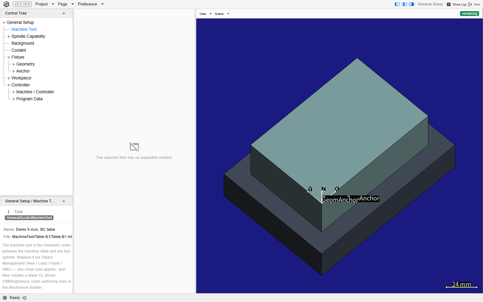
The branch selected on a demo project, at /general-setup?tree=equipment/machine-tool. The panel
under the tree is the whole of it: the Object Management (⋮) button, a type badge reading
GeneralXyzabcMachineTool, and the Name: and File: lines naming the chain in force and the
file it came from. The middle column reads The selected item has no expanded content. — this
branch brings nothing to it — and the canvas is drawing the stock on its fixture.
Note
The equipment canvas does not draw the machine until you ask it to. The Scene dropdown
above the canvas carries a Solid group whose Machine checkbox starts cleared, so a chain
that loaded perfectly still leaves that canvas showing only the fixture and the workpiece. Tick it
to bring the machine into the same scene — or open the /machine-tool route below, whose canvas
draws the chain on its own.
Attaching a chain to a project
A chain file is not a project's machine until it is loaded onto one. The branch root's Object
Management (⋮) menu is where a chain arrives and leaves:
| Entry | What it does |
|---|---|
| Load | Picks a .MachineTool or .mt file from the project or the administrator directory and installs it as the project's chain |
| New ClMillingDevice | Attaches a CL-driven blank device instead — the one chain type that needs no file, because it has nothing to configure |
| Save As | Writes the attached chain back out as a file |
| Copy / Paste | Carry the chain between projects as XML |
| XML | Shows the attached chain as XML and installs the result of an edit |
Every chain type other than the CL-driven device arrives by Load, Paste or XML. Installing one re-attaches the fixture and workpiece buckles and rebuilds the branch, so the rest of the equipment follows the new machine without being touched.
Tip
The shipped machines are one folder deeper than this picker opens. This menu's picker offers
the project folder and the administrator directory as its two roots, and the shipped resource
library is the Resource folder inside that administrator directory — so a shipped chain is
reached by opening Resource, then MachineTool. The /machine-tool route's own picker lists
that library as a root of its own and opens straight into it, which is the shorter way to the same
files; its Load installs onto the project exactly as this one does.
A Load from a file also re-points what the project saves. A chain picked from inside the project folder is remembered as a path relative to that folder, and one picked from the shipped resource library relative to the resource root — which is what keeps a project save from writing over a shared resource file. New ClMillingDevice clears that reference instead, so the fresh chain is saved inside the project rather than over the file the previous one came from. Paste and an XML apply leave the reference exactly as it was.
Checking what is attached
The /machine-tool route is a screen of its own for the same chain: the identity beside a canvas
that draws it. It carries no Page-menu entry and is reached by typing the URL. Its fields show
the chain rather than edit it — the name and the note are read-only there — but the folder button
beside them is a working Load, greyed out only until a project is open.
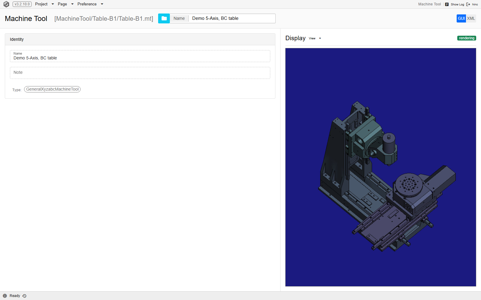
The route on the same demo project, at /machine-tool. The header names the file the chain came
from and repeats its name; the Identity card below carries the read-only name, the empty note
and the type chip; the GUI / XML toggle at the right swaps that card for the chain's XML;
and the Display panel draws the five-axis chain the file describes.
Building the chain
Structure is assembled in the Mechanism Builder and saved with its Save As Machine Tool entry. That save checks none of this: a mechanism whose end anchors are mis-cased or missing is written out without a word, and the mistake surfaces only later, on the screen where the file is loaded onto a project. What that page cannot tell you is what to call things: the chain reads its own topology by keyword, so the names below are not labels but the mechanism by which the machine works at all.
- Name the motion axes on the branches. A linear axis is a branch named
X,YorZ; a rotary axis is a branch namedA,BorC. Use each keyword at most once — a machine without a given axis simply has no branch carrying that keyword. - Give each axis branch a matching transformer. A branch named
X,YorZmust carry a Dynamic Translation, and one namedA,BorCa Dynamic Rotation. The keyword and the transformer kind are read together: a branch correctly named but left on a static transformer contributes no axis, and the machine ends up with one fewer than it looks like it has. - Name the anchors that hold the chain together.
Ois the ground anchor,basethe machine base,tthe tool-end anchor that tools connect to, andwthe worktable-end anchor that fixtures and workpieces connect to. The machine needs exactly onetand onew. The two are checked one at a time and the worktable end goes first, so a chain missing both is refused naming onlyw;tis named on the next attempt, oncewis in place. A second refusal after a rename is the next keyword, not a new fault. - Give the anchors shapes. Optional, and driven from the builder's Geometry card.
- Save the topology as a machine tool file, then attach it to a project as above.
Important
Every keyword is matched exactly as written. The motion axes are upper-case X, Y, Z,
A, B, C; the ground anchor is upper-case O; and the base and the two end anchors are
lower-case base, t and w. A name differing only in letter case names nothing at all. A
mis-cased axis is silent — that axis is simply absent — while an end anchor that is missing or
mis-cased stops the file loading, with a message naming the keyword it wanted:
This kinematic chain has no worktable-end anchor named ‘w’. When the mechanism carries that
same letter in the other case, the message adds the rename — The mechanism carries ‘W’, which
differs only in letter case; the keyword is matched exactly, so rename it to ‘w’. — and when the
anchor is simply absent, or named something else entirely, the first sentence stands alone.
Branch direction is free: the motion, the axis keywords and the default collision pairs all read a
branch the same way round. Pointing every branch away from the ground anchor is a readability
convention — it makes the structure read outwards, ground → base → motion axes → the t and w end
anchors.
The names also decide what can collide with what. A machine file asking for its collision pairs
to be generated is answered by walking the chain twice, from O to t and from O to w. That
walk is also where the two end anchors are checked, so such a file — the form Save As Machine
Tool writes — is refused by the Load itself. A file that lists its collision pairs explicitly
instead is read without the check and arrives intact; it is refused one step further on, when the
chain is installed onto the project and its kinematics are rebuilt, with the same message reported
against the install rather than the load.
Everything named on the way becomes a collidable component; the four structural keywords are dropped
from both walks, the tool holder, cutter shank and cutter flute are added to the tool side and the
fixture and workpiece to the table side, and every pair across the two sides is generated except
workpiece against cutter flute — that one is the cut, not a collision.
Where the numbers come from
The most convenient approach is to assemble the machine in CAD, position the moving elements at the machine origin — the position at which every machine coordinate reads zero, generally the home position — and then:
- Export the main components as individual STL files from that one coordinate system, and set each into its anchor.
- Measure, in the same CAD coordinate system, the tool-end anchor, the worktable-end anchor and a point on each rotary axis' pivot, and enter those coordinates into the topology.
- Expect the axis directions from the base to the worktable end to come out negative. That is relative motion rather than a mistake: moving the table one way moves the tool the other way through the chain.
Keep the meshes coarse. A machine carrying too much mesh is slower to open and slower to check for collisions, so export the components at the resolution a picture of the machine needs rather than at the resolution CAD produced them at.
Example: a small five-axis vertical milling machine
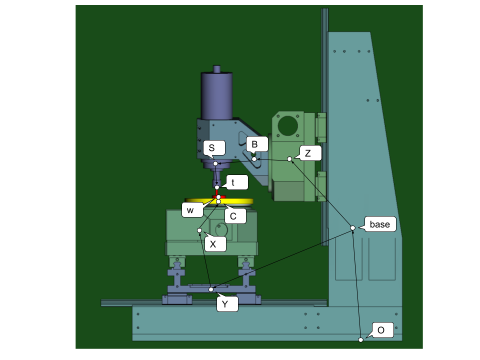
A worked example, complete with its STLs: B1.zip.
The machine it describes:
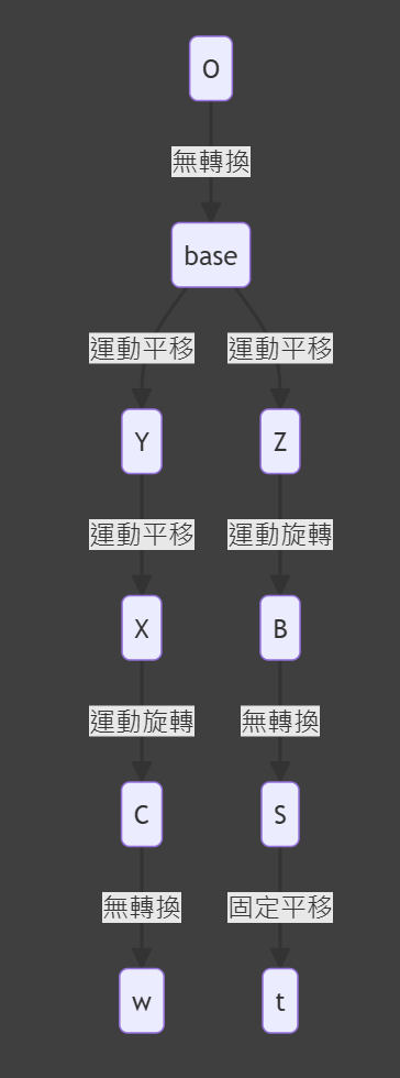
And the topology those anchors and branches form:
Laying a machine on its side
A horizontal machine is built exactly like a vertical one and then laid down:
- Create the topology from the machine's own axis coordinates.
- On the branch between the ground anchor and the machine base, set a rotation of 180 degrees about a normalized axis direction of (0, 1, 1).
A machine tool file can also carry this same connectivity as a short bracket notation for hand-editing the XML — the grammar is Machine Chain Code.
See Also
- Mechanism Builder — how to drive the editor the steps above are performed in
- Project Data Checklist — what to collect from the machine owner before building this
- Anchor — placing the fixture, workpiece and tool onto the chain built here
- Machine Chain Code — the bracket notation for the structure built here, and what it cannot express
- Fixture — what the table buckle built here then carries
- Spindle Capability — what this machine's spindle delivers, which the chain itself does not describe
- Controller — the brand whose per-axis rows this chain's axes fill
- Setup — the rest of the pre-simulation configuration