Workpiece
The workpiece is the stock the machine cuts. Setting it up means giving it the shape it starts as and the shape it should end as, placing it in the machine, choosing how finely it is meshed, and saying what it is made of.
Where it is
The General Setup page, at /general-setup, reached from the menu bar's Page dropdown. Select
the Workpiece branch of the Control Tree (/general-setup?tree=equipment/workpiece). Whichever
node you select opens its editor below the tree in the same dock, and the canvas beside them draws
the workpiece in the shared equipment scene.
A project carries its workpiece with it, so there is nothing to load: the branch root has no load or save button, and every part of the workpiece is edited through one of its child items. Those children appear once a project with a workpiece is open; until then the root shows a summary and a caption asking for a project to be opened or created first — see Projects. Attaching it to the machine is the anchor task below.
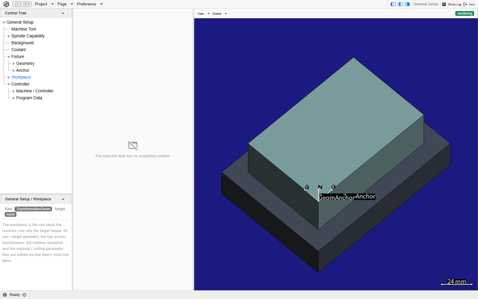
The branch with the root selected, at /general-setup?tree=equipment/workpiece. The root itself has
no editor — the caption in the middle column says so — while the canvas draws the stock sitting on
its fixture, with the workpiece's two anchors labelled at the corner they are placed on.
The two shapes
Selecting Raw Geometry or Target Geometry opens the same Geometry type kind picker the fixture's geometry slot carries — see Fixture — over a different list of kinds for each slot.
| Slot | What it is | Kinds offered |
|---|---|---|
Raw Geometryequipment/workpiece/raw-geometry |
The stock as it arrives, before the first cut. This is what the run removes material from. | Box3d, Cylindroid, StlFile, TransformationGeom, GeomCombination, MeshedGeomFile |
Target Geometryequipment/workpiece/target-geometry |
The finished part. The cut result is compared against it when a geometry difference is run after the program. | Box3d, Cylindroid, StlFile, TransformationGeom |
MeshedGeomFile is a shape already meshed into a voxel cube-tree, stored as a .wct file. The
target must produce a surface mesh to be compared against, so that kind is not offered there.
A new project has a workpiece but no raw geometry. Creating one leaves the Raw Geometry slot empty, so picking a kind there is the first thing this branch needs — until it is done there is nothing for a run to remove material from. The Target Geometry slot is optional: it is what a geometry comparison after the run measures against, and a run without one still cuts.
Where it sits
Anchor (equipment/workpiece/anchor) holds the two transforms that place the workpiece.
Geom To Fixture (.../anchor/geom-to-fixture) puts the workpiece geometry on the fixture's
workpiece buckle — one of the four named assembly anchors the
scene is built on — or, on a project carrying no fixture, straight onto the machine's table buckle.
Geom To Program Zero (.../anchor/geom-to-program-zero) places the program zero, the NC origin,
relative to that geometry. Setting them is Anchor; which direction to align program
zero in — and why that depends on planning a new job versus reproducing a recorded one — is
Program Zero Alignment.
Mesh and material
Mesh (equipment/workpiece/runtime) carries one field, Initial Resolution in mm, chosen
from a fixed powers-of-two ladder running from 0.0009765625 to 16. The panel's hint is that a
smaller resolution means a finer voxel grid and a slower run; what the number actually is and how to
pick it are Mesh Resolution. It seeds the run's machining
resolution when the project is opened.
Important
Keep the stored value on that ladder. The dropdown only offers ladder values, but a project arriving from an older generation, a script or a migration can carry something else — 0.4 mm is the one seen most often. Such a value is not a compromise between two rungs: the run rounds it to the next finer rung and uses that, so 0.4 mm builds the same 0.25 mm mesh at the same cost while the project reads as though it were coarser. Set it to the width it actually builds. The number then means what it says, here and in the Machining Resolution mission row that mirrors it.
Material (equipment/workpiece/material) holds two references to pre-prepared files. Each is a
file row whose Select dropdown offers Browse Resource… and nothing else — unlike the
coolant row beside it, these two do not offer a plain Browse…, so the picker always opens in
the shipped resource library, already in that resource's own folder. Loading one fills the read-only
Name and Note below it.
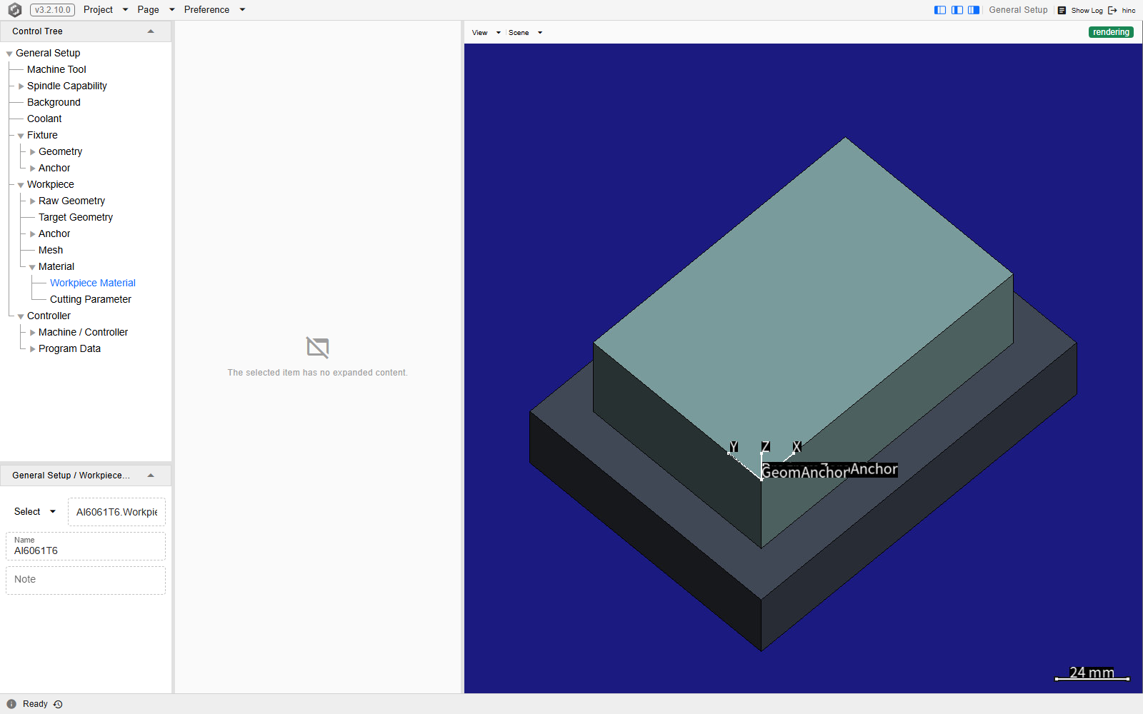
Workpiece Material selected on a demo project, at
/general-setup?tree=equipment/workpiece/material/workpiece-material. The file row holds the
material the project already carries, and the Name below it reads the name out of that file
while the Note is empty — both are read-only, because they belong to the file rather than to the
project.
- Workpiece Material (
.../material/workpiece-material) — a.WorkpieceMaterialfile: the physical properties the cutting-force physics reads. - Cutting Parameter (
.../material/cutting-parameter) — an.mpfile: the milling-force coefficients for that material. One file serves the whole run, whichever cutters it uses.
See Also
- Anchor — the two transforms above, and the order to place the machine, fixture and workpiece in
- Program Zero Alignment — which way to align the program origin once the workpiece is placed
- Fixture — what holds this workpiece on the table, and the buckle its Geom To Fixture transform lands on
- Mesh Resolution — how to choose the Initial Resolution, and the thin wall a coarse mesh loses entirely
- Milling Force Parameter Training — where a cutting-parameter file comes from when no shipped one fits
- Setup — the rest of the pre-simulation configuration