Mesh Resolution
MachiningResolution_mm is the edge length of the cubes the workpiece is built from, and it is the single largest lever on how long a simulation takes. It is also the setting most often set once and forgotten, which is expensive in both directions: too fine and a run that should take minutes takes hours, too coarse and a feature the program is supposed to cut is not there to be cut.
Choosing a Value
Work coarse first. An early run answers questions — does the path collide, is the force roughly where it should be, does the optimizer have room — that do not need a fine mesh, and it answers them in a fraction of the time. Refine only for the final optimization pass, where the geometry that comes out is the deliverable.
As a planning figure, a simulation run takes somewhere between 2% and 150% of the actual machining time, spanning that whole range depending on the mesh and the step count. That is wide because it is genuinely a choice, not a property of the machine.
Where the time actually goes, and which of the two costs is currently the bottleneck, is in CPU Usage During Simulation. The short version: at the fine resolutions real NC work needs, geometry removal dominates and a finer mesh is much slower; once the mesh is coarse enough that removal is cheap, the per-step costs dominate and coarsening further buys nothing.
What Value You Actually Get
The number you type is a request, not the width. The workpiece is carved out of a cube grid that starts from one fixed root cube and is halved level by level, so every width the engine can actually build is a power of two in millimetres:
... 2 - 1 - 0.5 - 0.25 - 0.125 - 0.0625 - 0.03125 ...
A request that is not one of those is rounded to the next finer one, never to a coarser one, so the mesh you get is never worse than the mesh you asked for. The consequence worth knowing is that a value chosen off the ladder buys nothing:
| Requested | Actually built |
|---|---|
| 0.5 | 0.5 |
| 0.4 | 0.25 |
| 0.3 | 0.25 |
| 0.25 | 0.25 |
| 0.2 | 0.125 |
| 0.125 | 0.125 |
0.4 mm and 0.25 mm produce the same mesh, at the same cost. 0.4 is 0.25 wearing a misleading label: it reads as a coarse, cheap setting and runs as a fine, expensive one. If 0.25 mm is finer than the run needs, the next value that changes anything is 0.5 mm — and going the other way, 0.125 mm is another eight times the voxels, not a small step.
The ladder bottoms out at 0.001953125 mm. A finer request is clamped to it, so the finest entry offered in the workpiece's Initial Resolution list builds the same mesh as the one above it.
The width only ever goes finer
A mesh that exists cannot be coarsened. Every cut takes the finer of the width already built and the width being asked for, so raising Machining Resolution above the mesh the workpiece was built at does not simplify anything — the request is dropped and the run keeps the mesh it has.
This is why the two settings are not interchangeable. The workpiece's Initial Resolution is what builds the mesh and is therefore the memory setting; Machining Resolution gates how fine a newly cut surface may go, and can only ever refine. To make a run cheaper in memory, coarsen the Initial Resolution — coarsening Machining Resolution alone changes nothing about the stock that is already there.
It still changes the time, and by a lot, because the same number sizes two other things: the tessellation of the cutter's own solid, and the number of engagement layers per step. Both are per-step work that is thrown away again, so a coarser Machining Resolution can cut the run time several-fold while the memory figure does not move at all. A run that got faster without getting smaller is this, not a mystery.
Pick from the ladder and the number shown in the mission row is the number the run used. That matters beyond tidiness: a recorded mesh is built at whatever resolution is in force when the record runs, so an off-ladder value is silently baked into the cache as its rounded neighbour.
What It Costs in Memory
Far less than it costs in time, which is the opposite of what four rungs of the ladder — sixteen times finer, and so four thousand times the voxels — leads most people to expect. Measured by sweeping one case across five rungs with the program and the step count held fixed — a cylindrical blank, one roughing program, 199,242 steps every run:
| Mesh width | Play time | Process memory outside the managed heap |
|---|---|---|
| 2 mm | 10.5 s | 665 MB |
| 1 mm | 15.3 s | 688 MB |
| 0.5 mm | 31.2 s | 722 MB |
| 0.25 mm | 76.6 s | 826 MB |
| 0.125 mm | 242.9 s | 1,456 MB |
Sixteen times finer costs 23 times the time and 2.2 times the memory. Two things flatten that second column, and it is worth separating them:
- Most of the figure is a baseline the mesh does not set. The coarsest run in the sweep already sits at 665 MB, and the whole sixteen-fold refinement adds 791 MB on top of it. Read the column as increments rather than as totals: the ratio at the bottom of the table is diluted by everything in the figure that would be there at any mesh width.
- The increments grow slowly at coarse widths and then accelerate. Halving the width added 23 MB, then 34, then 104, then 630 — each increment about 1.5, then 3.1, then 6.1 times the one before it, a local exponent climbing from roughly 0.6 to 2.6. A cube stops subdividing as soon as the surface inside it is a single flat facet, so while the mesh is coarser than the part's facets and curvature, refining mostly buys nothing. The volume-scaling intuition is not wrong; it only arrives once the width is below the feature scale, and by then it arrives fast.
A big workpiece moves the same curve up: where the stock is a large imported solid rather than a small procedural blank, there is far more surface to subdivide and the mesh-dependent part dominates much earlier.
Do not judge the mesh by the process's peak memory. On a long run most of that figure is the per-step data the run accumulates, which lives on the managed heap, scales with the number of steps and not with the mesh at all — and it moves the other way when the mesh is refined, because a slower run allocates more slowly and the collector commits less. The two cancel: measured on a larger case across a four-fold refinement, peak memory fell slightly while the mesh's own footprint grew by nearly 40%. Read the two apart before concluding anything.
What the Mesh Does Not Change
For a representative test case — downward circular slot milling with varying width and depth — the physical values move within about 20% across the full range of mesh widths. The simulated forces, torques and temperatures from a coarse first pass are therefore already informative; they do not become a different answer when the mesh is refined.
The visible geometry is a different matter, and it is what the three runs below show. Workpiece 70 × 50 × 50 mm:
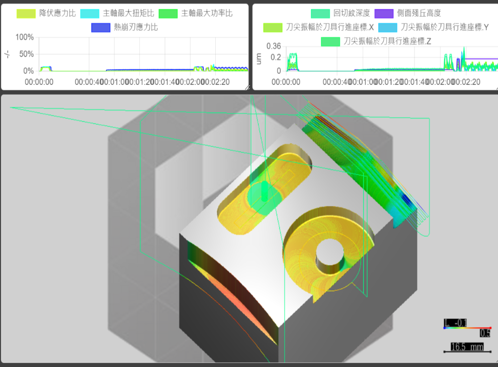 Mesh width 0.125 mm
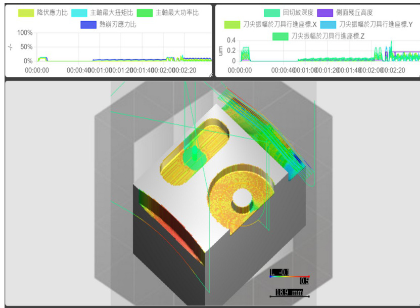 Mesh width 0.5 mm
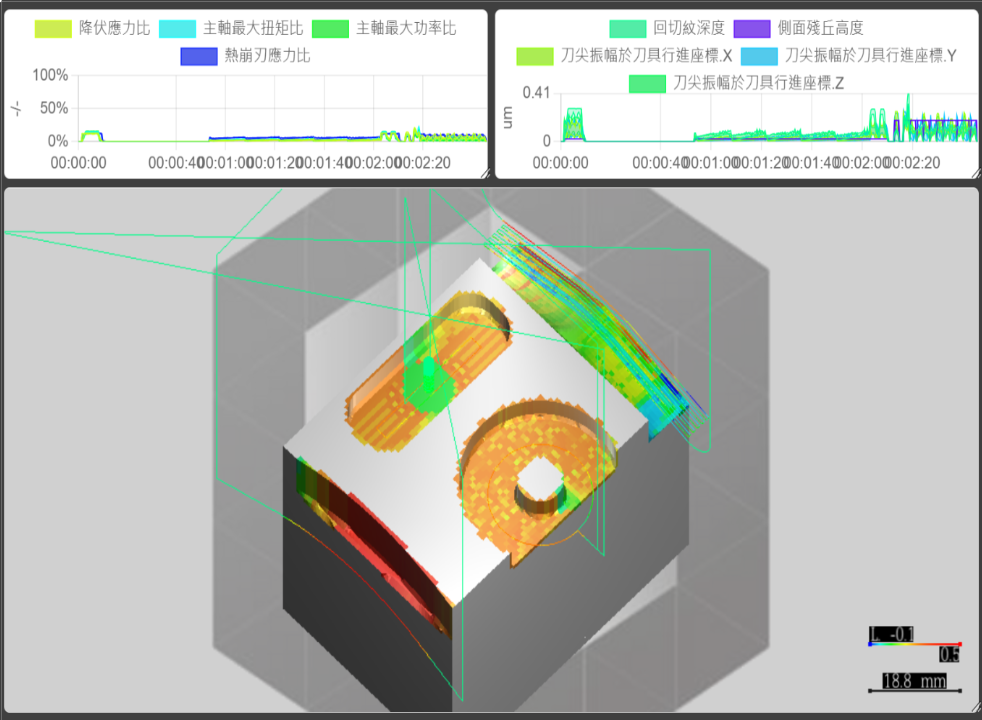 Mesh width 1 mm
The Failure Mode Worth Knowing
A thin shell thinner than the mesh width can disappear entirely. The test case above has no thin shell, which is why its physical values are so insensitive; a part that does have one behaves differently, because the material the cutter should be meeting is not represented at all. Where the workpiece has a wall, web or floor thinner than the mesh width, the mesh must be finer than that feature before the run says anything about it.
The related and much smaller effect is quantization ripple in the per-step ratios, which a finer mesh reduces — see Process Machinability.
See Also
- CPU Usage During Simulation — which of the two cost drivers a given mesh width puts in the way
- Process Machinability — the mesh-quantization ripple in the availability ratios, and why it is an artifact rather than a signal
- Workpiece — where the initial resolution is set, on the branch carrying the stock it applies to