Showcase: AI agents working with HiNC
This page shows, one published case at a time, how an AI agent uses HiNC to establish, evaluate and help a machining project.
HiNC simulates a CNC machining job (machine, fixture, stock, tool and holder, NC program) and reports what the cut does: cutting depths and forces, times, collisions, and the difference between the machined part and the design.
Each case below is told this way: what the agent was given and what was missing, how it built and ran the simulation through HiNC's web API and managed the job, every small dilemma it met (what it saw, how it found the cause, how it solved it), and what the result tells a machining engineer, a teacher or a student, and someone deciding whether to work this way.
The cases come from public sources whose licences allow reuse; none comes from a client. The HiNC project the agent built is its working material and is not published. If you want the data, fetch it from the original source listed with each case, and keep the attribution the source asks for with anything you share. Original links may stop working some day, so where the licence allows, this site keeps a backup copy of the original files (the last column of each case's table), with the licence and attribution the source requires. The full case records, with every dilemma in detail, are in the Showcase section of the HiAPI documentation site.
NC optimization
Some of the cases below, taken one step further. An AI agent hands the programs a case has already accepted, and for some cases an earlier or hand-revised version of them too, to HiNC's feed optimization, replays the optimized programs on the same simulated machine, and compares machining time, spindle load, cutting force, tool deflection and the machined shape before and after, against pass criteria it wrote down first. Each page also says what the agent protected from the optimizer, such as finishing passes kept at their programmed feed.
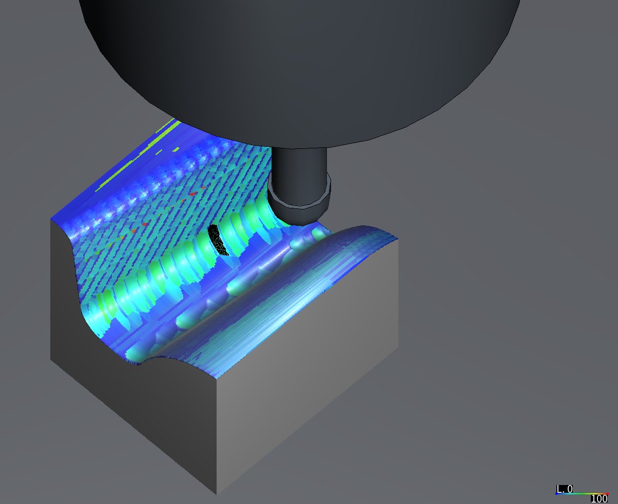
Connecting-rod forging die, optimized
3-axis
HiNC's feed optimization on the programs of a connecting-rod forging die: kept from running slower than the hand-revised programs it takes 24.5 % off them, and it shows that the R1.5 ball's corner stays over its limit even at the lowest feed.
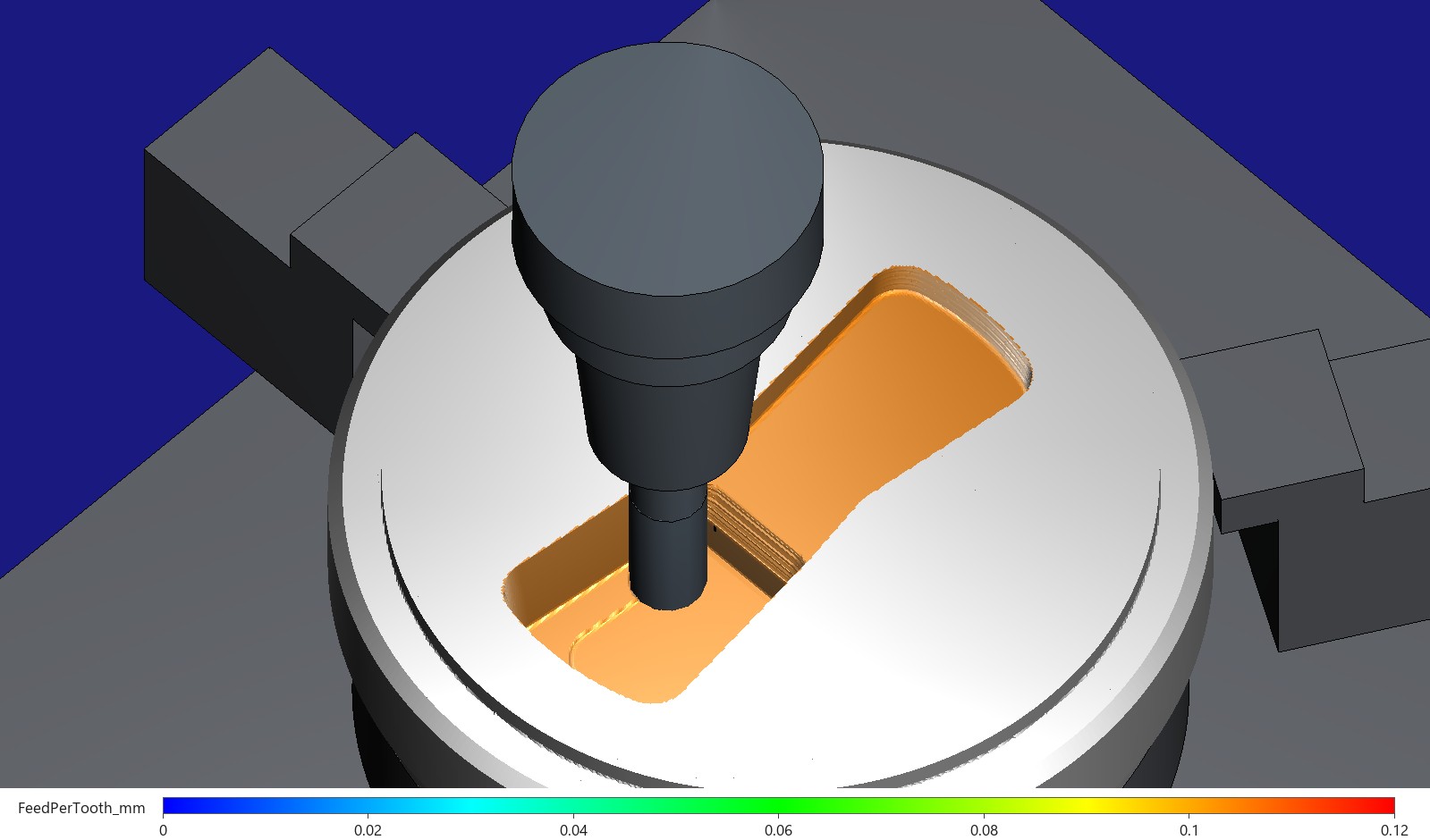
Heatsink porthole die, optimized
3-axis
HiNC's feed optimization on the eight programs of an aluminium extrusion die: 608.6 down to 529.1 minutes, the roughing about a third shorter, the finishing held at its programmed chip, and no feed that keeps the 3 mm fin-relief cutter within 30 µm.
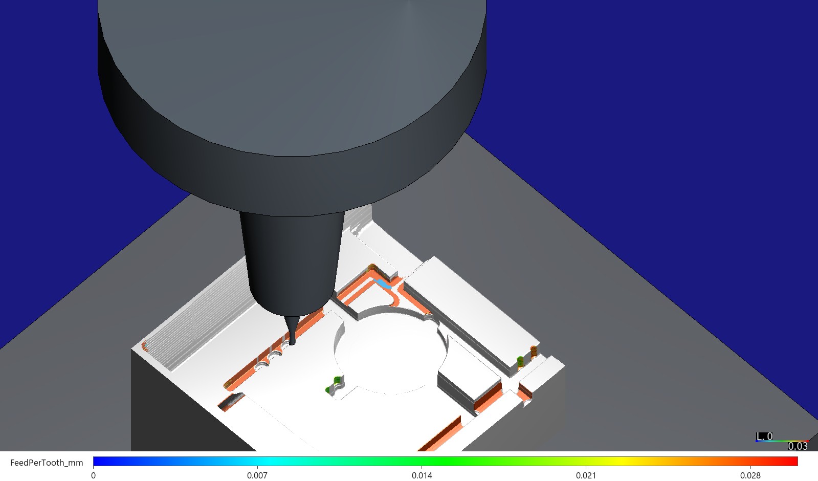
Antenna-cover injection mould, optimized
3-axis
HiNC's feed optimization on the micro-tool programs of an injection-mould insert: the moving insert drops from 12.0 to 7.9 hours, most of the saving feed through air, and the optimizer finds by itself the corners the agent's hand rules had found; no feed holds the Ø1 mm tool's bend within 10 µm.
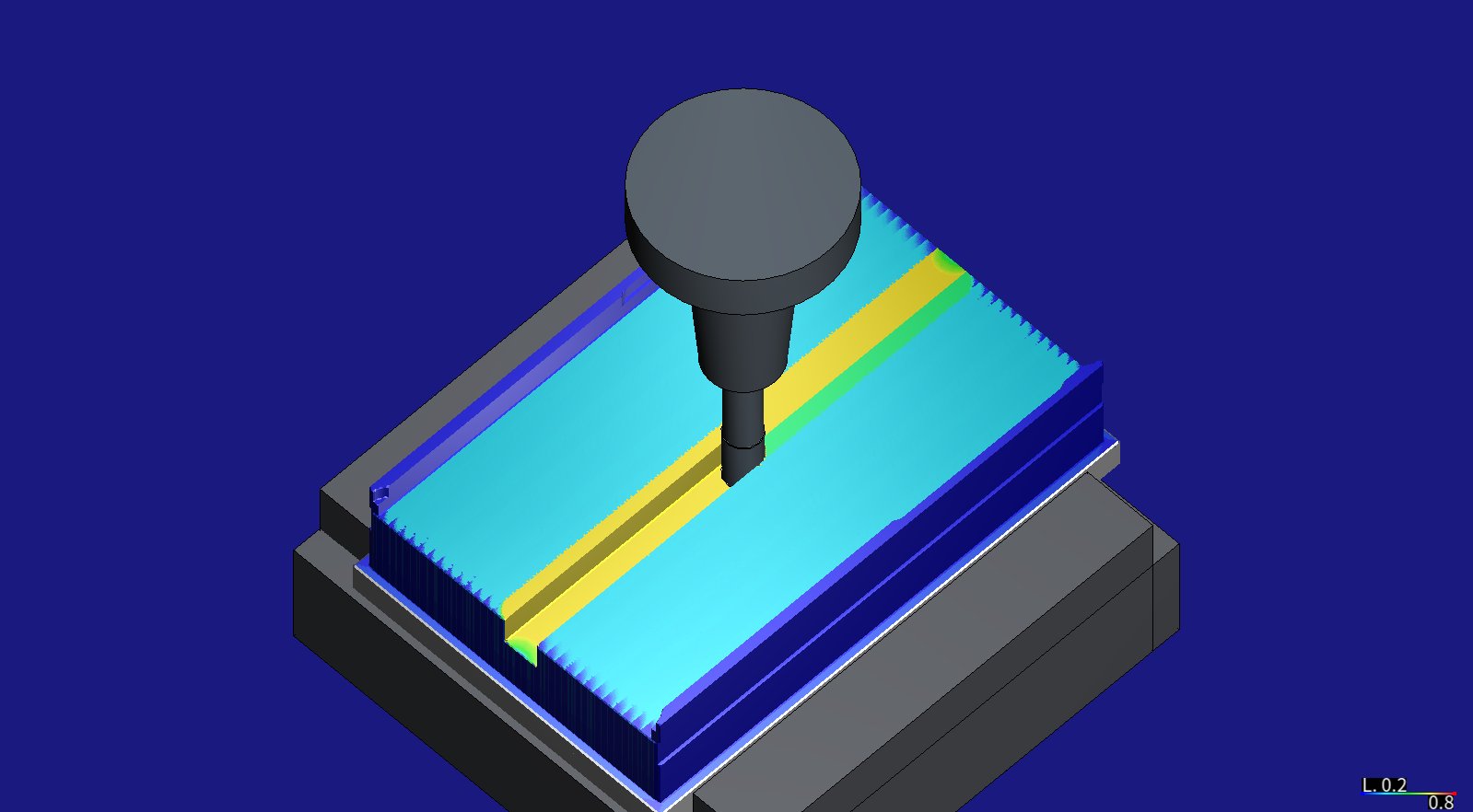
Jetson AGX Thor enclosure, optimized
3-axis
HiNC's feed optimization on three programs of an aluminium enclosure: 76 minutes off, the 12 mm roughing limited by the chip the agent allowed rather than by the spindle, the cover's finishing held within 25 µm by a ceiling per line, and 37 % off a grille that only looked as if it were at its limit.
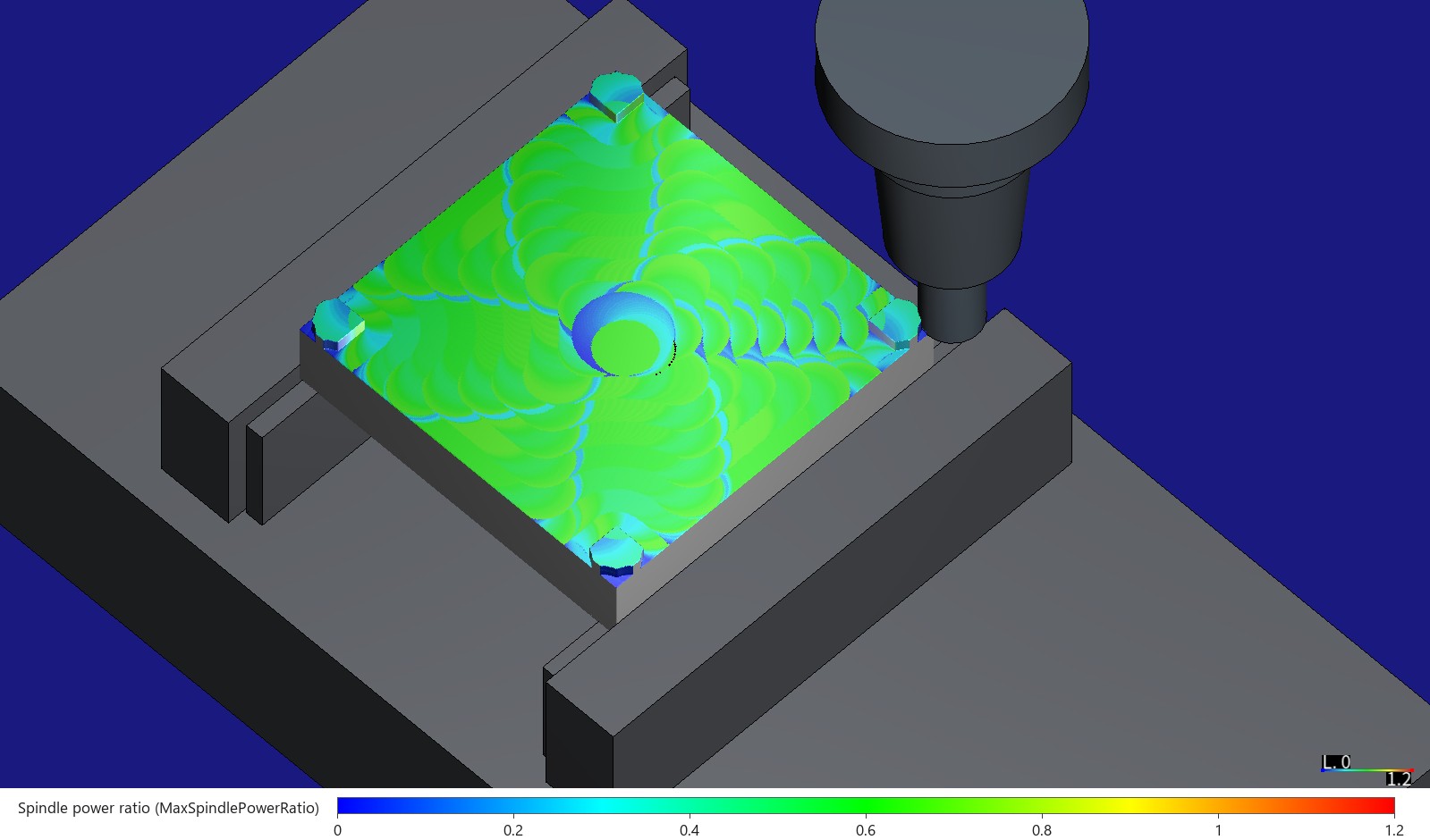
SpaceTeamSat1 CubeSat structure, optimized
3-axis
HiNC's feed optimization on the first clamping of a CubeSat frame plate: the agent's first CAM program brought to the spindle target and the finishing deflection limits for 3.8 % more time, 19.9 % faster than the program the agent had tuned by hand, and 9.9 % taken off the hand-tuned program itself, two thirds of it from its ramps.
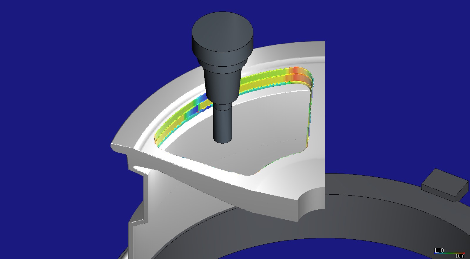
17-inch forged wheel, optimized
3+2 / 5-axis
HiNC's feed optimization on the five-axis programs of a 17-inch forged aluminium wheel: 17 min 25 s down to 9 min 40 s, with the finishing passes kept at their programmed feed and no line slower than programmed.
Error terms
Cases with constant geometric errors of the machine built in, most on a case accepted in this Showcase and some on a paper's test part built for the purpose. An AI agent gives axes or the spindle of the simulated machine error terms, each a static branch of its own just before the axis (a squareness between two linear axes, the location or the tilt of a rotary axis, a spindle out of tram), at the size a paper measured where one printed it, plays the case's programs with the errors off, on with the controller unaware of them and, where the controller could compensate, on with the errors known to it, and checks the tool-tip offset and the part's deviations it predicted before the first play.
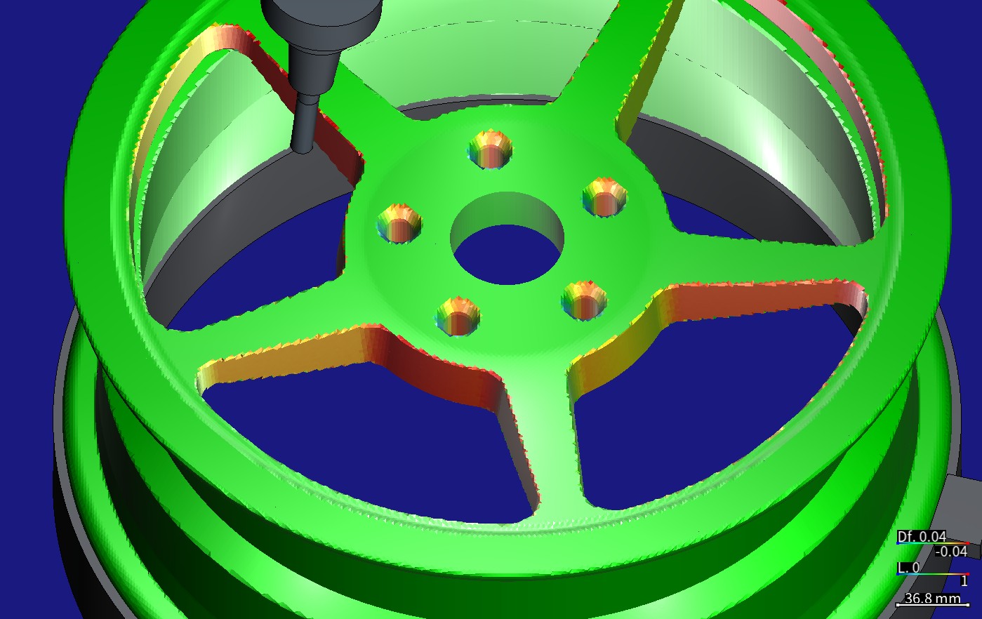
17-inch forged wheel, C table 20 µm off-centre
3+2 / 5-axis
One constant machine error on the five-axis programs of a 17-inch forged aluminium wheel: with the C table turning about a centre 20 µm off and a controller unaware of it, the five spokes come out 38–41 µm thinner and the bolt circle 36 µm off-centre; a controller that knows the error cuts the nominal wheel.
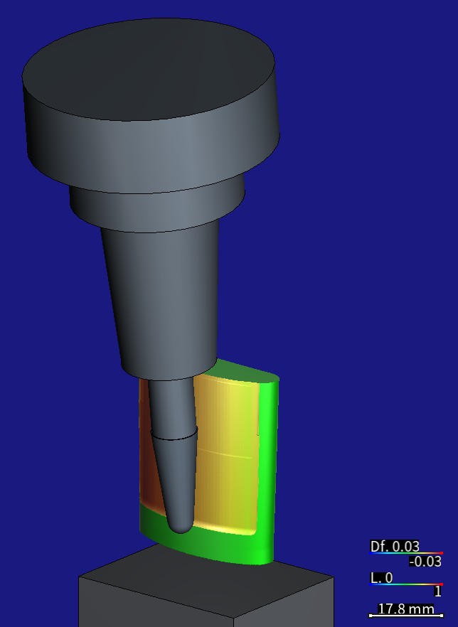
BCAM thin blade, C axis 0.02 mm off
5-axis
The BCAM blade on a five-axis machine whose C axis is 0.02 mm off, with a controller unaware of it: under M128 the blade comes out 0.010–0.027 mm thicker with the NX finish and 0.011–0.029 mm thinner with the G1 finish; a controller that knows the error cuts the nominal part.
NIST cone frustum, C axis 10 µm off-centre
5-axis
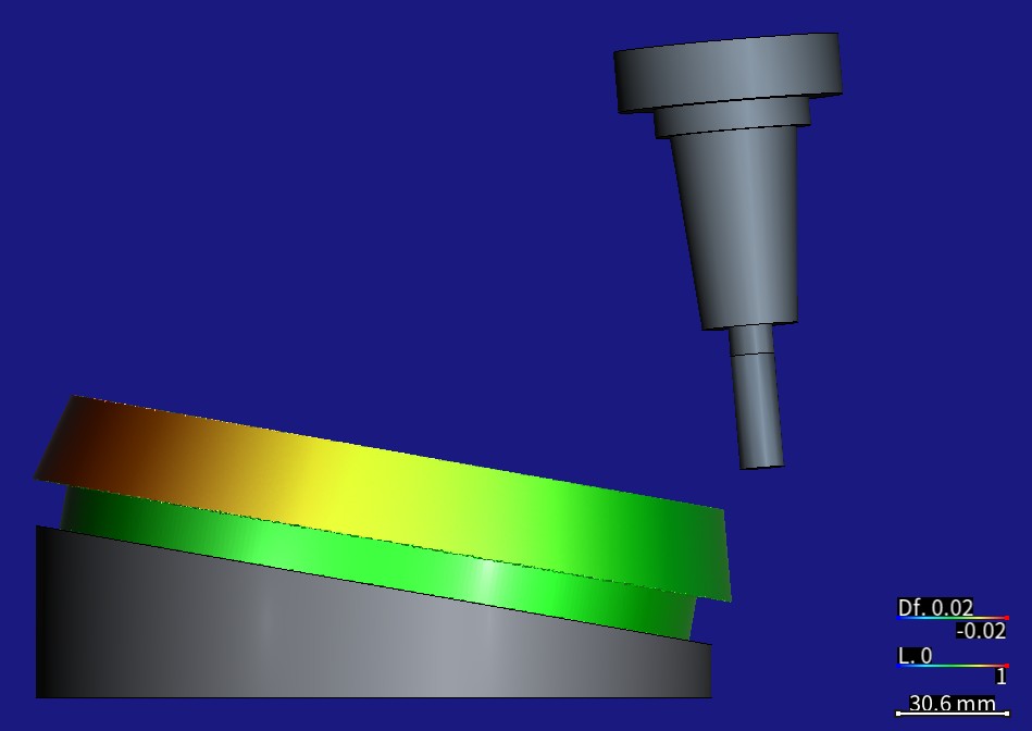
A NIST paper names one error for the machine that cut its five-axis cone frustum, and here that error is built into the case's machine: the C axis turns about a centre 10 µm off, and a controller unaware of it cuts most of the cone side up to 18 µm too deep, yet a roundness check at mid-height reads only 3 µm; a controller that knows the error cuts the nominal part.
RPTU part 8, three squareness errors of 24–56 µrad
3-axis
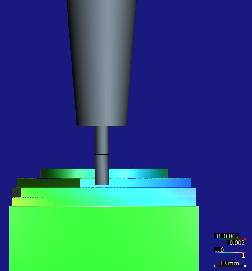
Three squareness errors measured on a vertical machining centre, 24, 33 and 56 µrad, put into the machine of RPTU benchmark part 8, the ISO 10791-7-style test piece: with a controller unaware of them, the walls move by at most 1.7 µm, the block's faces give the three angles back within 1 %, the 30° square's corners change by half the X–Y angle and the Ø54 boss becomes two lobes.
Roundness test part, three squareness errors of its machine
3-axis
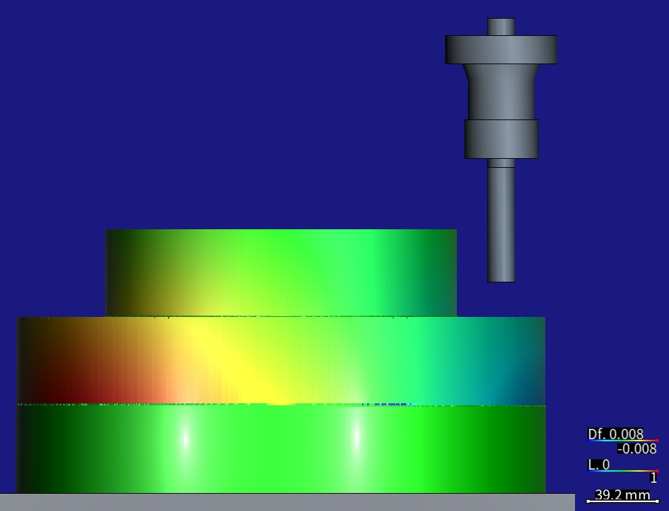
The test part of a paper on volumetric compensation, cut in simulation on a machine with the three squareness errors the paper measured: only the X–Y squareness turns the circles oval, 3.5 µm on Ø300 as γ × the tool-centre radius predicts, while the Z squareness tilts the cylinders' common axis instead. That one squareness explains a third to a sixth of the roundness the paper measured before compensation.
Deep slot in AA7050, Z axis 0.003° out of square
3-axis
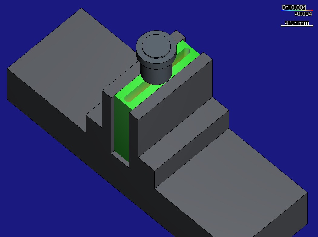
One constant machine error on a 74 mm deep slot in AA7050, roughed by full-depth plunging or by layers and finished alike: with the Z axis 0.003° out of square with Y and a controller unaware of it, both long walls lean toward +Y together, 3.9 µm at the bottom, the width does not change, and the two roughing strategies cut the same slot.
NISTIR 6868 test part, X–Y squareness of 6.87″
3-axis
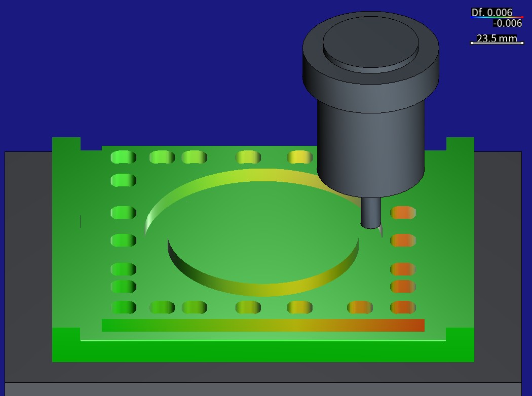
The X–Y squareness a laser ball bar measured on a production machining centre, −6.87″, cut in simulation into the test part of a NIST report, which that machine cut 21 times: the 150 mm square becomes a parallelogram with about 5 µm at most on its walls, the two rows of hole centres, fitted the report's own way, read −6.8717″ back, and the slot comes out 1.64 / 1.69 µm out of round, under a tenth of what the report's CMM measured.
Mars rover wheel, A axis tilted 0.005°
4-axis
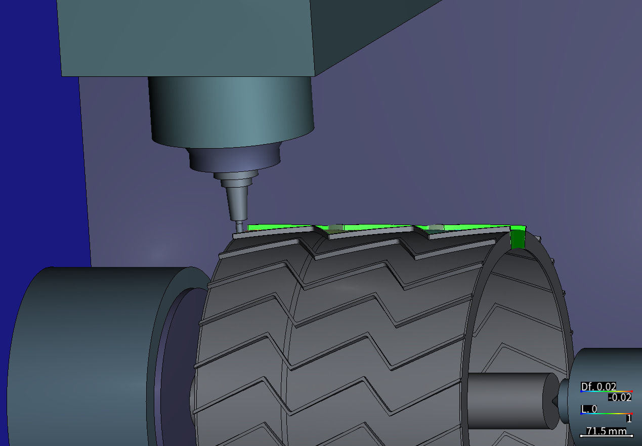
One constant machine error on the four-axis programs that mill a Mars rover wheel's 0.75 mm skin: with the A axis tilted 0.005° against the X travel, 46 µm over the 531 mm between centres, and a controller unaware of it, the skin runs from 0.733 mm at the faceplate end to 0.767 mm at the tailstock end, the same all round; without RTCP, a controller that knows the tilt cuts the same tapered skin.
Sphere V-grooves, tool tip 10 µm below the B axis
5-axis
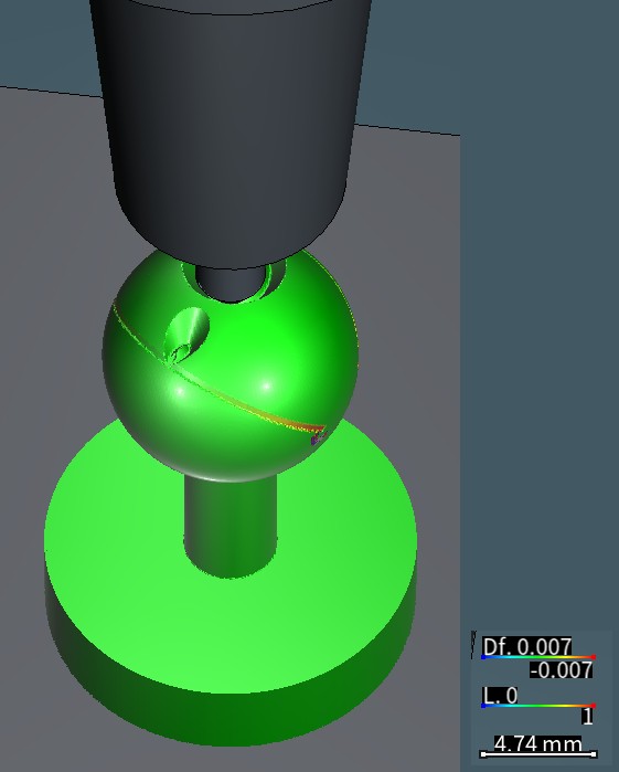
A research team's five-axis program for two V-grooves on an 11 mm sphere, cut on a B-head, C-table machine whose tool tip sits 10 µm below the B axis: with a controller unaware of it, both grooves are cut deeper toward the equator, from 0 at their top to 7 µm at their ends, a depth error that follows the height alone. The program is in machine coordinates, so a controller that knows the error cuts the same grooves: the correction belongs in the post-processor, or the tip back on the B axis.
Cubic machining test, eight rotary-axis errors
5-axis
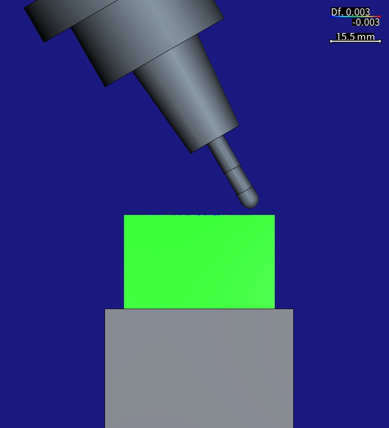
The cubic machining test of a 2021 article, nine zones on one face cut under TCP, rebuilt on a B/C table-table machine with the eight rotary-axis errors the authors measured with a ball bar. With a controller unaware of them, the tilted zones stand 0.43 and 0.23 µm above the centre and every face tilts by up to 1.97 µm; a 10 µm tool-length error moves the tilted zones 1.34 µm, and a calibrated controller still leaves them 0.05 µm high.
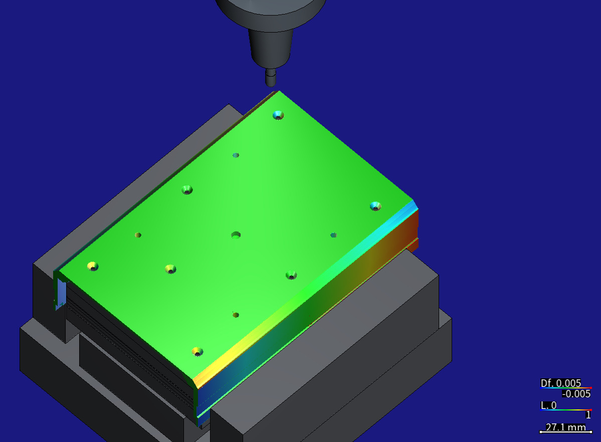
Thor enclosure bottom shell, X–Y squareness of 0.003°
3-axis
One constant machine error across the turn-over of an aluminium enclosure's bottom shell: with X and Y 0.003° out of square and a controller unaware of it, each set-up alone shears the walls by only ±4.4 µm, but the turned-over part's two set-ups shear it opposite ways, their faces 8.85 µm apart at the ends of the long walls; seated in soft jaws machined on the same machine, the wall seam closes and the mismatch moves to the wall ends.
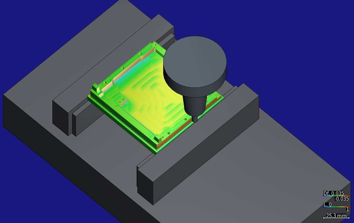
CubeSat side panel, Z axis 0.2 mrad out of square
3-axis
One constant machine error on a CubeSat side panel in three clampings: with the Z axis 0.2 mrad out of square with Y, the factory-acceptance limit of a light milling machine, and a controller unaware of it, every face toward ±Y of the plate milled flat shifts and leans, the end bars' end faces by 2.0–2.8 µm, while the holes drilled into its end faces lean 0.2 µm per millimetre and their mouths, on the touch-off face, stay where they are.
Dies and moulds
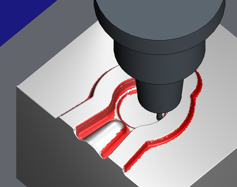
Connecting-rod forging die
3-axis
An agent designed this closed-die forging die for an aluminium connecting rod from one drawing and one photo. HiNC showed the R1.5 ball's tip bending up to 112 µm in the rib grooves' R1.5 corners, against a 12.5 µm limit.
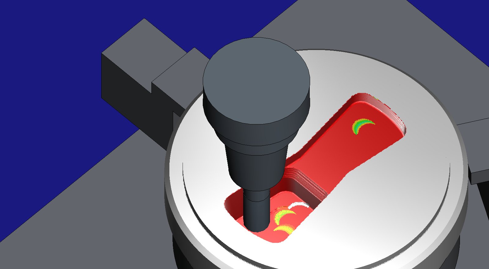
Heatsink porthole die
3-axis
An agent rebuilt this aluminium extrusion die from a paper's drawings. In HiNC the 3 mm cutter bends 106–130 µm in the fin slots, against a 30 µm limit, and needs 7.0 h, so the fin relief goes to EDM.
Antenna-cover injection mould
3-axis
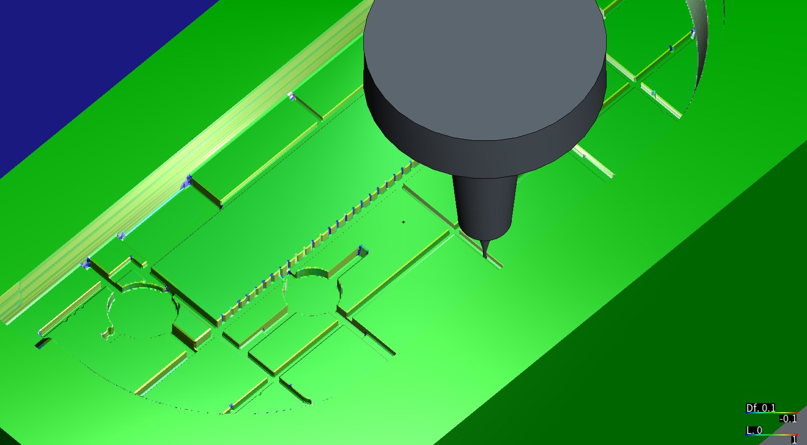
An agent derived both inserts of an injection mould from a published antenna cover and wrote every toolpath with its own CAM. A load HiNC read exposed a false step of up to 2.4 mm that the agent's own code had put into the mould.
Wheels
Mars rover wheel
4-axis
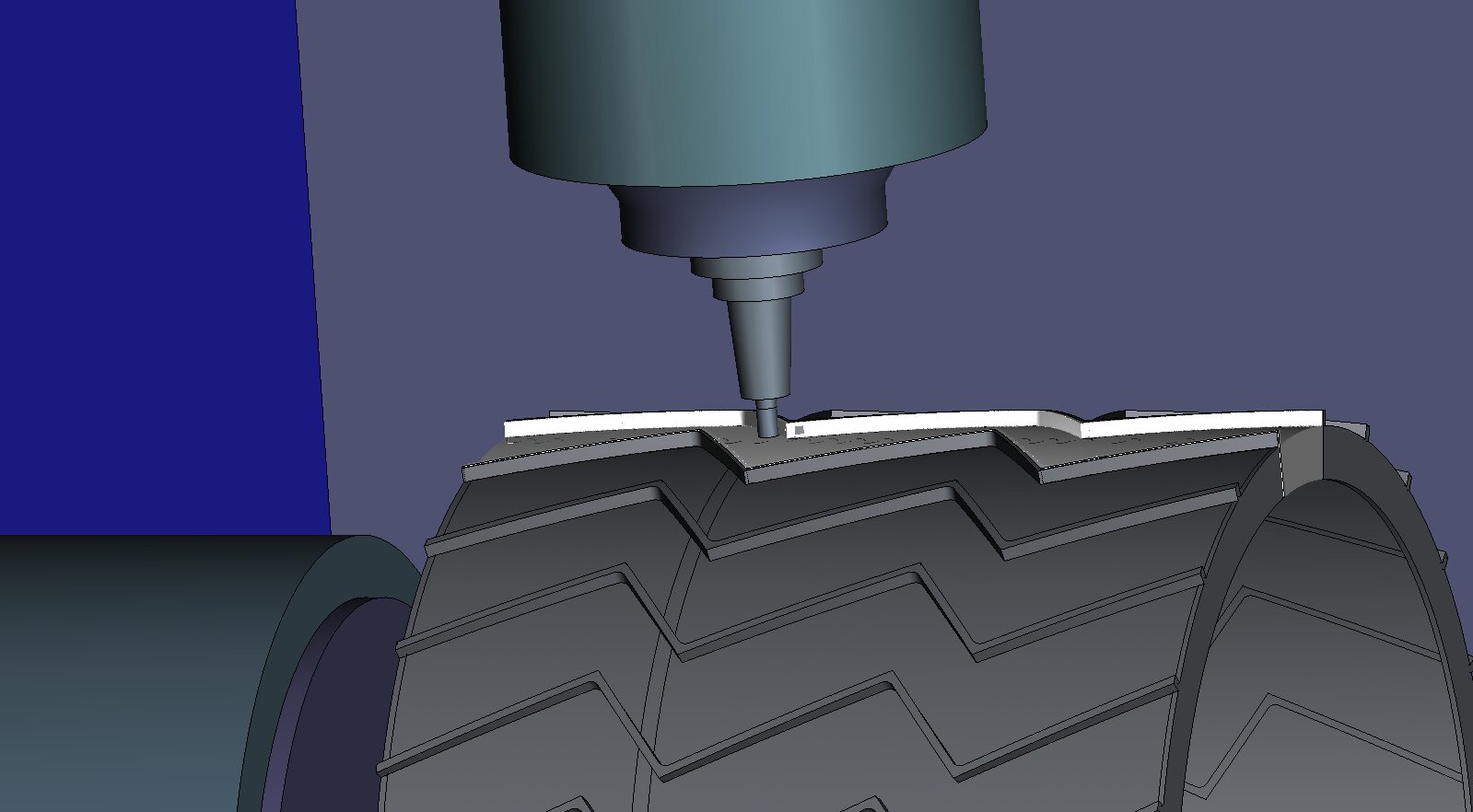
An agent modelled Curiosity's wheel from published numbers and a photograph, and programmed one chevron groove for a four-axis machine. On the simulated part, 5,344 radial lines found the 0.75 mm skin at 0.750–0.759 mm, with no hole.
17-inch forged aluminium wheel
3+2 / 5-axis
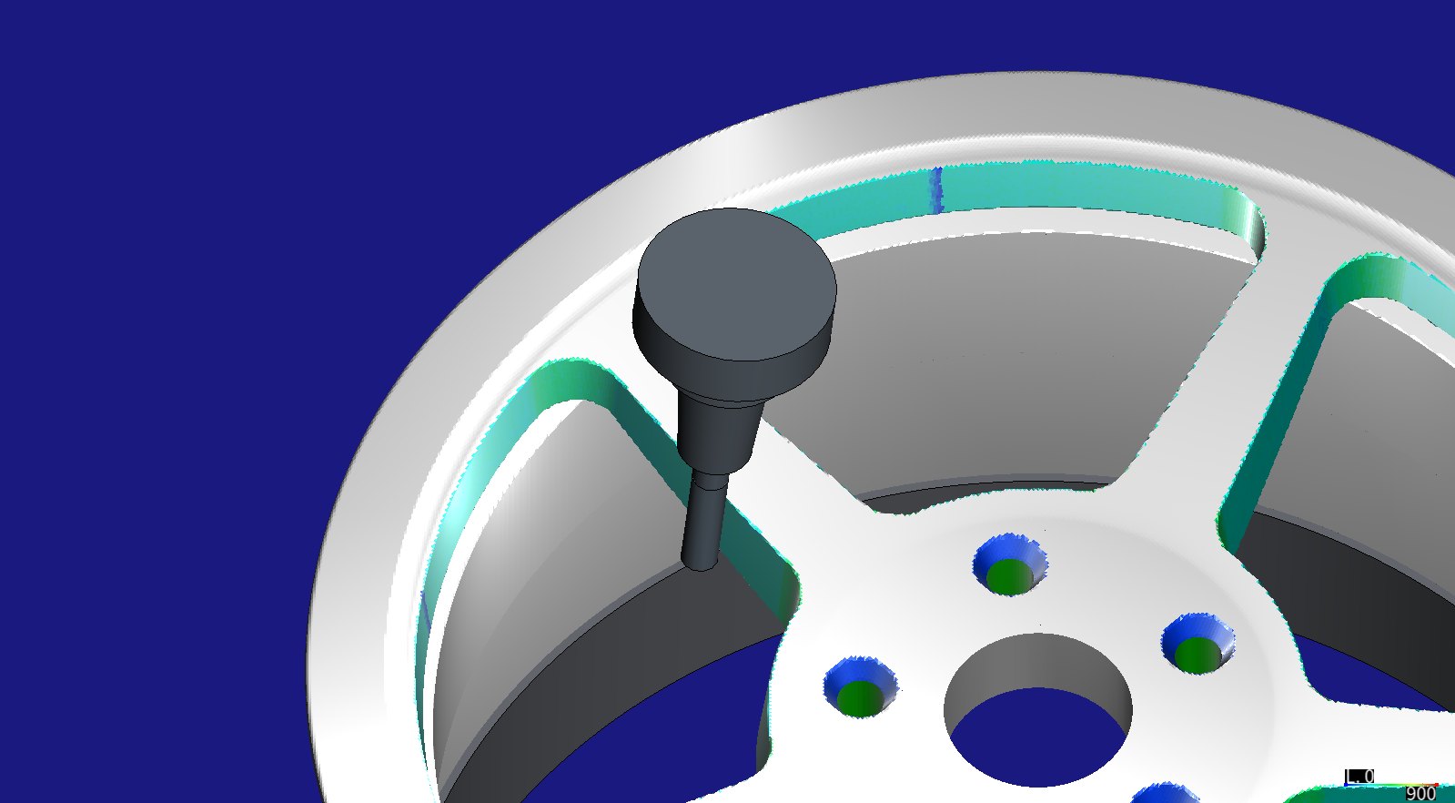
A one-piece forged 6061-T6 wheel that an agent designed from three public numbers and programmed in two five-axis set-ups. HiNC's feed optimization cut machining time from 17 min 25 s to 9 min 36 s, within the spindle's rating.
Impellers and blades
BCAM thin blade
5-axis
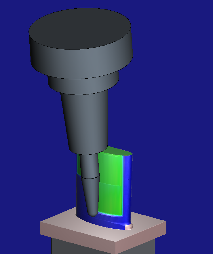
A paper's thin steel blade, with NX and G1 flank finishes but no machine, holders or blade position. In HiNC, NX leaves up to +0.14 mm on the lower face; G1 stays within 0.024 mm at the paper's 25 points.
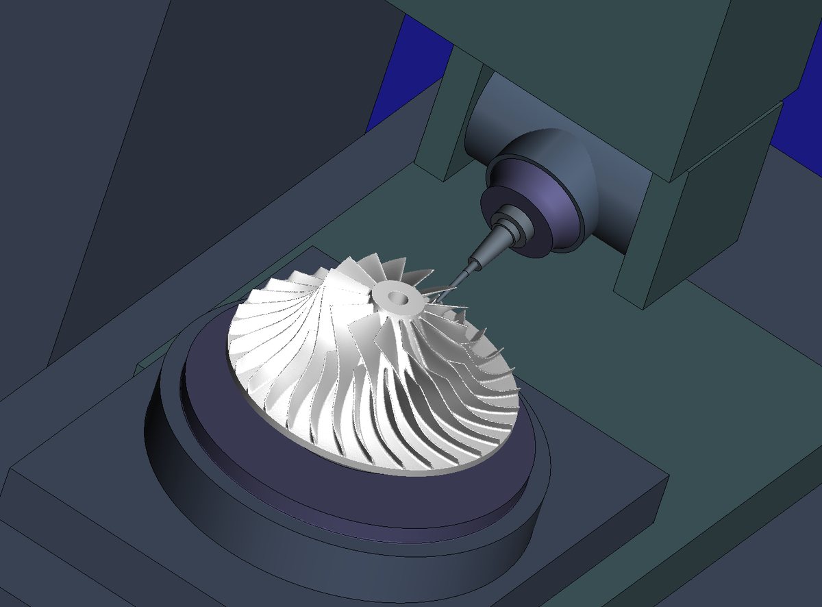
NASA HECC centrifugal impeller
5-axis
A centrifugal impeller 431.8 mm across the tips, given only as unitless coordinates; the agent wrote the five-axis path. HiNC read the tool on the last hub finish far above its stress limit (stress ratio 3.5); reworked, it peaked at 0.94, under the limit.
Enclosures and structural parts
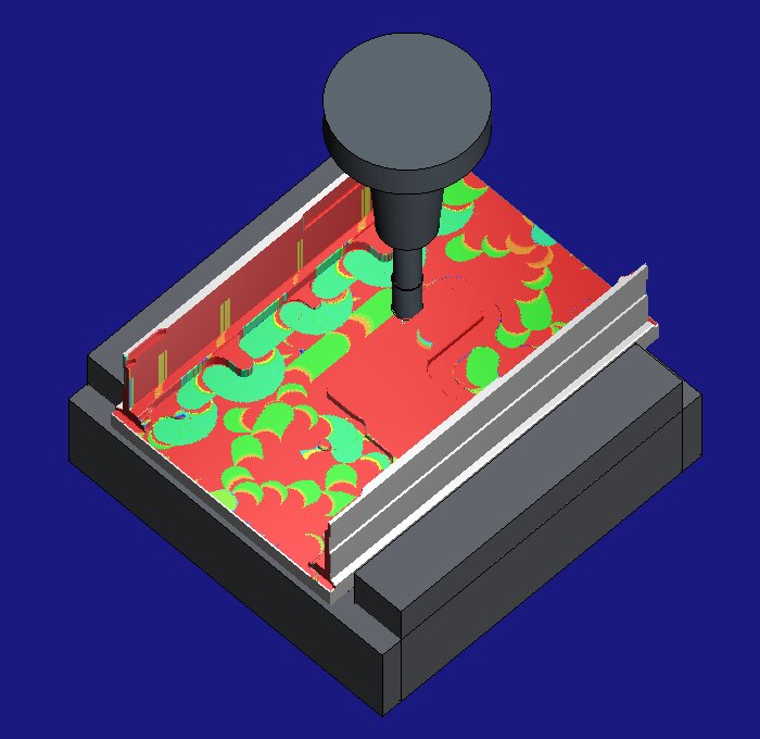
Jetson AGX Thor enclosure
3-axis
An agent wrote its own CAM for the four aluminium parts of an open-hardware enclosure, two set-ups each. Before any cut, HiNC caught a drill that would have hit the vice, a spindle asked for 3.3 times its rating and a 1.5 mm cutter bending 0.14 mm.
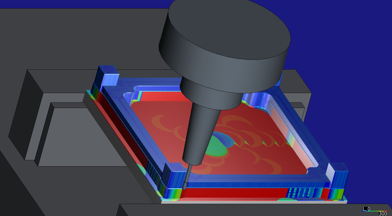
SpaceTeamSat1 CubeSat structure
3-axis
An agent wrote its own CAM for the six Al 7075 plates of a student team's CubeSat, in 24 clampings. HiNC showed the original programs asking the spindle for 1.6 times its rating and a 2 mm cutter bending 360 µm; the revised programs keep the finishing cutters within their deflection limits but for one step.
Test pieces and benchmark parts
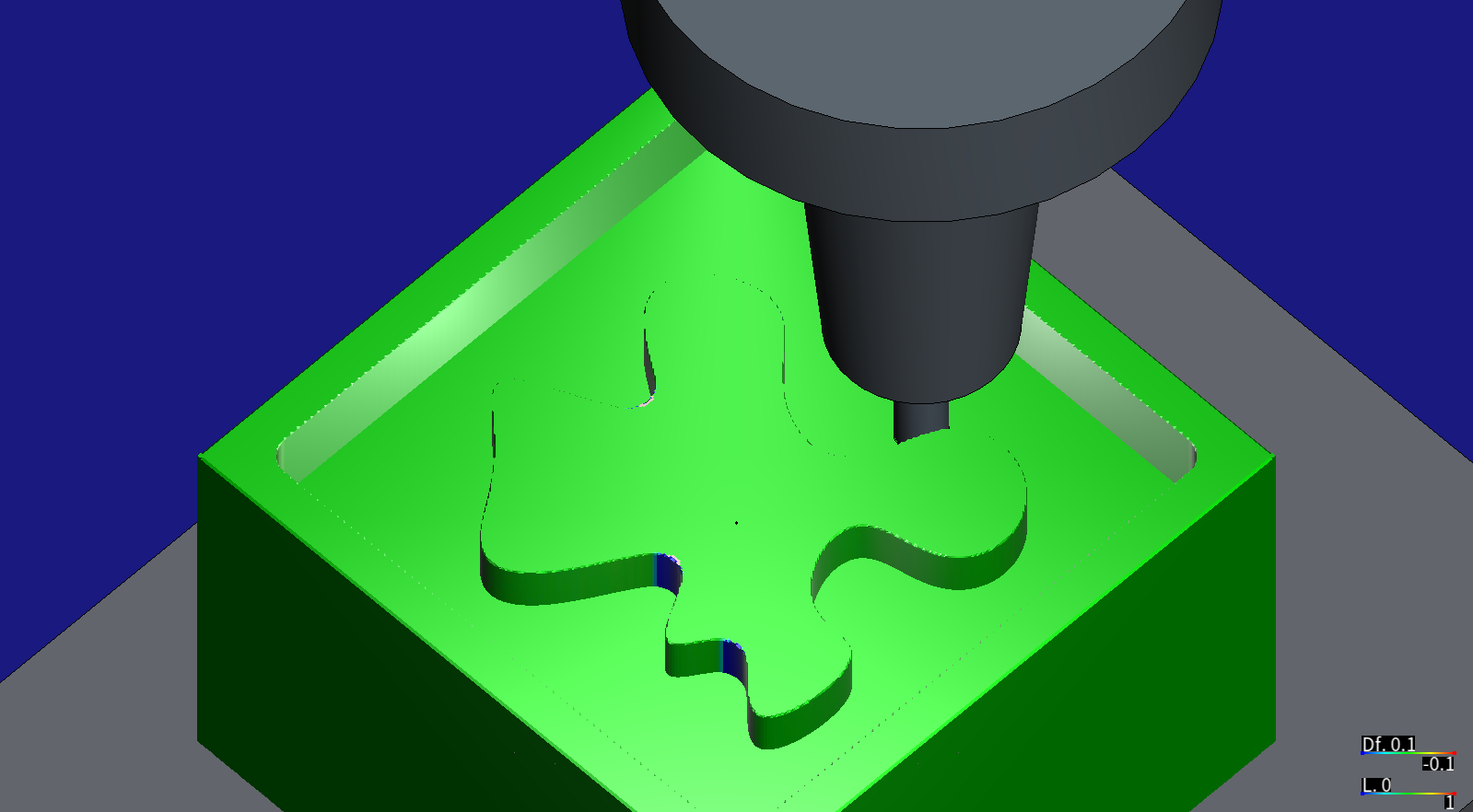
RPTU 3-axis milling benchmark
3-axis
Ten benchmark parts with STEP models and NC programs but no set-up. Agents derived each program zero and found the stated block 1 to 3 mm short; part 7's program leaves material up to 0.7 mm thick at the island's bay tips.
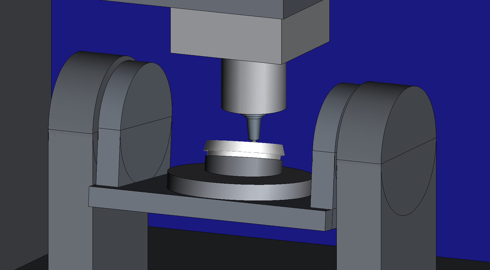
NIST five-axis test artifacts
5-axis
A cone frustum and a truncated square pyramid, given as drawings without model or program. The agent drew both and wrote the cutter locations; HiNC wrote the G43.4 program, and replaying it matches playing the cutter locations to 0.00001 mm in peak cutting depth.
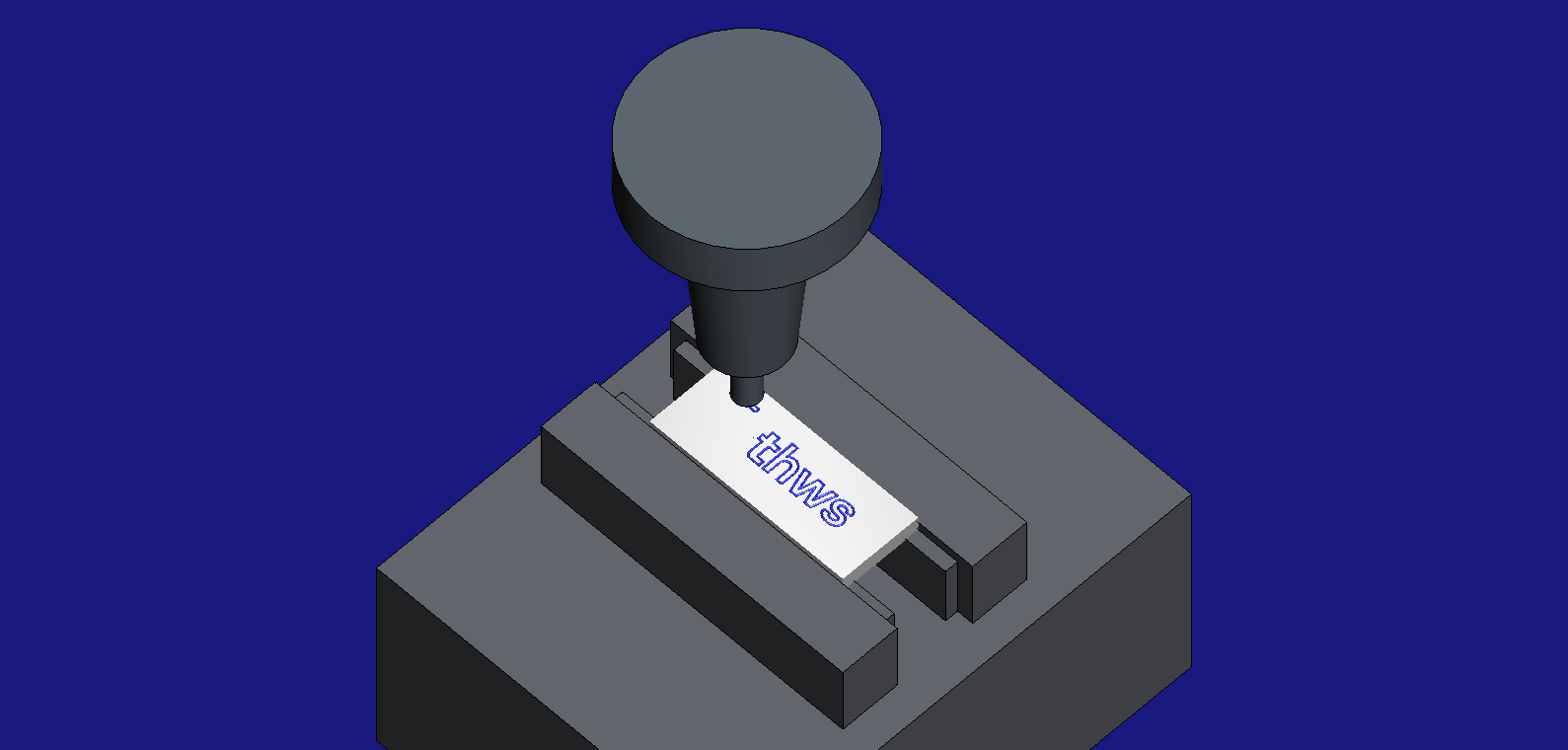
THWS keychain
3-axis
An engraved, drilled keychain plate from a Siemens 840D sl program, with no model or stock. The agent read the plate from the program; 13 of the 28.7 simulated seconds are 16 mm plunges and retracts at cutting feed.
Cutting experiments from papers
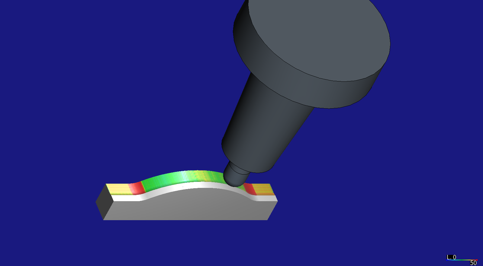
Ball-end finishing in five raster directions
3-axis
Convex and concave R45 faces from an article with no model or program; the agent made both. The force's swing along a pass, 1 % along the cylinder axis to 31–49 % across it, ranks directions as measured roughness does.
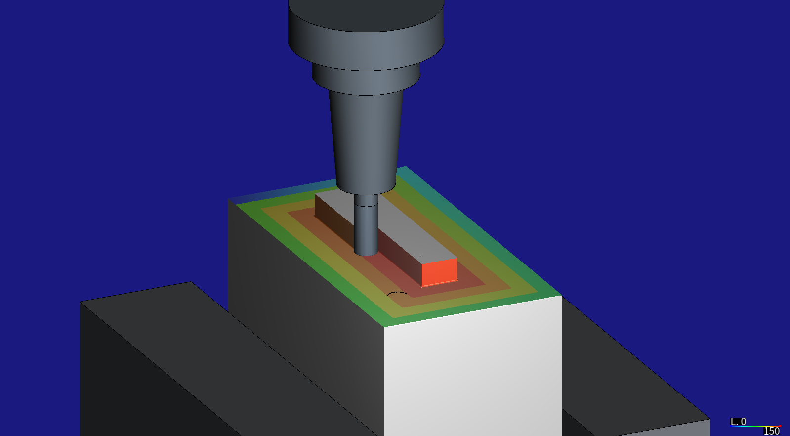
Rzeszow tool-life data set
3-axis
Fourteen end mills run to breakage in hardened 42CrMo4; the agent wrote the programs. Per cycle, HiNC wore the flank 1.67–1.69 times as fast at 8 mm radial depth as at 4.5 mm, the order the lives show.