V-grooves on an 11 mm sphere, the tool tip 10 µm below the B axis: both grooves deepen from 0 at their top to 7 µm at their ends, and a controller that knows the error cuts them the same (5-axis)
- Original source
-
NC programs: Liqiang Wu, Hanzhong Liu, Zhipeng Cui, Wenjun Zong, NC codes for a research in
fabrication of randomly distributed V grooves on a spherical surface, Mendeley Data, V1
(2023-09-04) — DOI 10.17632/bcskc575nm.1
(data set page). The data
set holds five NC programs and a short description, nothing more: no CAD model, stock, tool, material,
machine or measurement; of the machine its record says only "the five-axis machine tool". This case
plays one of the programs,
simulation_singular1_without_singularity_algorithm(sim1 below, 1,116 lines). The companion article, L. Wu, H. Liu, Z. Cui, W. Zong, Fabrication of randomly distributed V grooves on the great circles of a spherical surface using ultra-precision five-axis milling, Precision Engineering 85 (2024) 48–64, doi:10.1016/j.precisioneng.2023.09.005, is not open access and was not read. - Search keywords
NC codes for a research in fabrication of randomly distributed V grooves on a spherical surface,bcskc575nm,simulation_singular1_without_singularity_algorithm- Licence
- The data set is under Creative Commons Attribution 4.0 International (CC BY 4.0), as the licence field of its record gives it (read on 2026-09-29): "You can share, copy and modify this dataset so long as you give appropriate credit, provide a link to the CC BY license, and indicate if changes were made, but you may not do so in a way that suggests the rights holder has endorsed you or your use of the dataset." The NC files carry no statement of their own, and nothing in the data set is marked as belonging to a third party. The companion article is under its publisher's own licence and is not covered; nothing from it is used. The case takes the program only, and every picture here is a HiNC capture or a chart drawn from HiNC's results. The machine, the stock, the cutter, the holder and the set-up were derived or chosen for the base case, and the error for this case; the error's size and sign are not a measurement of any machine.
- Attribution
-
As the base case's source record gives it:
NC programs: Liqiang Wu, Hanzhong Liu, Zhipeng Cui, Wenjun Zong, "NC codes for a research in
fabrication of randomly distributed V grooves on a spherical surface", Mendeley Data, V1 (2023),
https://doi.org/10.17632/bcskc575nm.1. Licensed CC BY 4.0
(https://creativecommons.org/licenses/by/4.0/), provided as-is without warranties (CC BY 4.0
Section 5). Related article: L. Wu, H. Liu, Z. Cui, W. Zong, Precision Engineering 85 (2024)
48-64, https://doi.org/10.1016/j.precisioneng.2023.09.005. The authors do not endorse this case
or HiNC. Changes: none to the files; the programs are played as published on a machine, stock,
cutter and set-up made for this case.
The tool-and-holder pictures (and the shorter check runs) play a shortened copy of simulation_singular1: its lines 1–288 unchanged and line 289 stopped at its midpoint.
Tech Coordinate's agent added one error-term branch to the simulated machine, between the B axis and the spindle, and chose its kind, its size and its sign. The authors do not endorse Tech Coordinate, HiNC or this case. - About the case
- Wu and colleagues mill V-grooves on a small sphere by ultra-precision five-axis milling. Their data set gives two programs without their singularity algorithm, whose grooves pass the singular pose at B = 0, two programs for the same grooves with it, and the production program. sim1 cuts two V-grooves, one pass each, in machine coordinates X Y Z B C, with no RTCP and no G43. The base case built the whole set-up from the NC alone. Every five-axis block lies 5.4943 mm from program zero, and of 54 readings of B and C only one makes every groove a circle: a B head turning about the tool tip and a C table turning about the sphere centre, built as a generic machine with no maker's geometry. The agent chose the rest: a sphere of radius 5.5193 mm, 25 µm above the programmed radius, on a Ø4 stem and a Ø16 × 4 mm foot; a 60° V cutter with a 0.1 mm flat tip and a Ø3 shank, in a shrink-fit holder at 10 mm stick-out, for T01 and T04 alike. Played, sim1 dug the pit its singular block predicts: at line 289, C turns 179.88° inside one G01, and the cut comes within 3.6308 mm of the sphere centre, 1.863 mm inside the programmed sphere; a second pit lies where groove B passes near the pole. That base case has no page of its own; the full record of this case cites it. Here the machine gets one constant geometric error: the tool tip 10 µm below the B axis, a typical value the agent chose.
The story
A five-axis program written in machine coordinates is right only on the machine it was computed for. sim1 cuts groove A with T01 (lines 6–560) and groove B with T04 (lines 563–1114). Each groove climbs from near the equator, B about 60°, to its top, where B is about 0, the tool stands upright and the tip sits at Z 3.631, 4.12 mm off the C axis; then it runs down to the equator on the other side. The program assumes the tool tip lies exactly on the B axis, and the base case derived its machine from that very assumption. On a real machine, tool setting decides where the tip sits, and it is always off a little. With the tip 10 µm off, what do the two grooves look like, and does it matter whether the controller knows?
An AI agent put that error into the base case's machine: the centre of the B axis 10 µm above the tool tip, as if the tool were 10 µm longer than the 70 mm the program assumes, or the spindle nose sat 10 µm low in the B head. It is a static translation of 10 µm along the tool, named TipOffB, on a branch of its own between the B axis and the spindle, marked as an error term. HiNC puts an error term just before the branch of an axis or of the spindle, and this machine's spindle branch carried no rotation, so it played no spindle role. The agent first made it a spindle turning about the tool's own axis, which passes through the tip, and bound the Spindle role to it. HiNC's controller computes the machine coordinates as if the marked branch were not there, while the simulated machine moves and cuts with it whenever the project's Enable Error Terms switch is on, like a real machine whose controller does not know the error. A touch-off at B 0 would take the 10 µm into G54 Z. HiNC's P0 measures the machine as designed and does not, so the runs with the error typed G54 (−15, 0, +0.010) in by hand, as HiNC's manual advises for reproducing a shop's cut. The program was not changed.
Before the first play, the agent committed a plan with the tool-tip offset it expected, the deviation of every feature and seven pass criteria. A trimmed case played first: a shortened copy of sim1, lines 1–288 and half of line 289, which feeds in to B 60°, cuts the first half of groove A and parks the cutter at the bottom of the first pit. It was to check the build, the formula, the touch-off pose and the pit, and to show whether the real 10 µm could be read at all. Then sim1 played whole, at 0.0625 mm like every run here, geometry only, three times:
- error terms off: the nominal cut, which every comparison is measured against;
- off again, with HiNC's geometry difference (Diff) against the nominal cut: the noise floor;
- on, with the error marked, so the controller does not know it.
The trimmed case had a third run besides its nominal and its marked one: the mark cleared, as a controller with calibrated kinematics would know the error. The program goes to the axes as written plus the work offset, never through the machine's chain, so the plan expected that run to be identical bit for bit, not merely close, and one trimmed run was enough to show it.
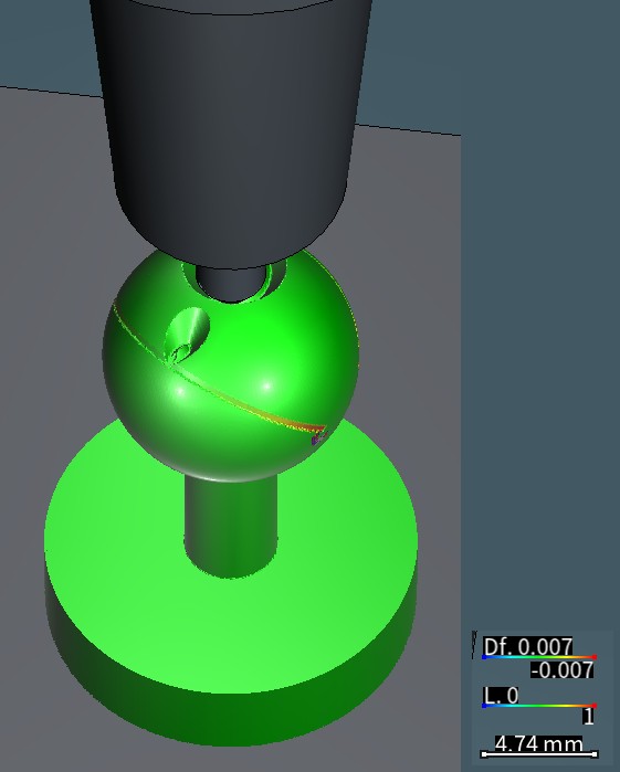

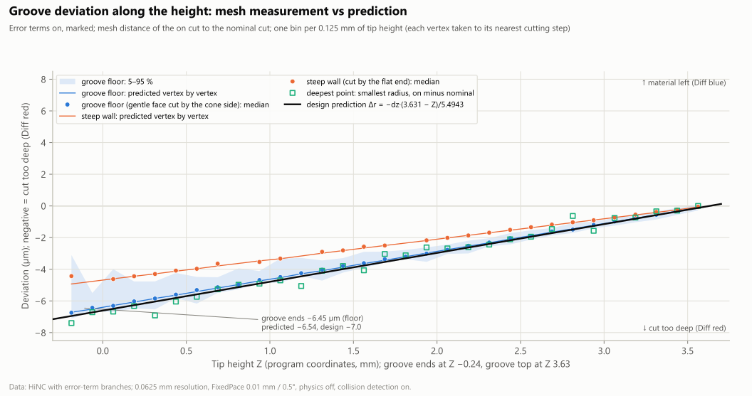
HiNC rendered these pictures on the base case's generic machine with the error-term branch the agent built in; the program is the authors', played as published, apart from the shortened copy behind the first picture. The colours are HiNC's geometry difference (Df in the colour bar) against the part the nominal run cut, on a symmetric scale of ±0.007 mm: red = cut too deep, blue = material left, green = 0. The cut parts were put back on the canvas with their Diff, not replayed; for the first picture, the shortened program brought the cutter into view. The grid is 0.0625 mm. The charts are drawn from HiNC's per-step results and the meshes of the cuts it exported.
| Key number | What it is |
|---|---|
| 10 µm | the error: the centre of the B axis 10 µm above the tool tip, along the tool, as if the tool were 10 µm longer than the 70 mm the program assumes; in ISO 230-7 terms, a location error of the B axis relative to the spindle, along the tool axis. A typical value the agent chose; this generic machine was never measured. A touch-off at B 0 takes it into G54 Z, so the runs with the error typed G54 (−15, 0, +0.010) |
| 1.8×10⁻¹⁴ mm | the largest gap, over the 4,961 cutting steps, between the measured tool-tip offset and the formula written before the first play, ΔCl = dz·(−sin B·cos C, −sin B·sin C, 1 − cos B) with dz = 10 µm: 0 at B = 0, 9.996 µm at B 59.97°. The machine's X, Y, B and C are those of the nominal run bit for bit |
| 48.6° | the angle the tool axis keeps to the sphere's normal all along both grooves, which makes the groove-depth error depend on the tip height alone: Δr = −dz·(3.631 − Z)/5.4943, 0 at the groove top and −7.0 µm predicted at the four groove ends |
| −6.45 · −7.33 µm | the groove at its four ends: the floor median over 127 vertices (−6.54 µm predicted vertex by vertex) and the deepest point (−7.0 µm designed). Those 7 µm are 28 % of the program's nominal 25 µm depth of cut |
| 0.29 µm | the largest gap between the floor medians of 31 bins along the height and the plan's formula. The steep wall reads 0.71 Δr and the floor 0.97 Δr, each as predicted; only the deepest point reads Δr itself |
| 3.63084 · 4.52138 mm | how close the cut comes to the sphere centre in the two pits, with the error as without it and as in the base case: the singular blocks pass at B ≈ 0, where the tip moves by 0.047 µm at most. 99.91 % of the 13,784 pit vertices lie within 0.5 µm |
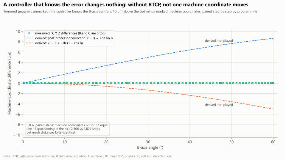
| bit for bit | the trimmed run with the mark cleared, as a controller that knows the error: the machine coordinates of 3,037 paired steps equal the marked run's, and the cut's mesh distances are identical byte for byte. Only line 16, a C positioning in the air, has 2,806 steps instead of 2,807 |
| 1 h 35 min | server time for the six plays at 0.0625 mm on the shared 32-thread server: three trimmed, 10.0–12.0 min each, and three whole, 20.6–21.0 min each with 16,018 or 16,019 steps. The heaviest peaked at 3.67 GB (3.42 GiB) of memory |
Four of its eight dilemmas
The usual error leaves no mark here
For a rotary axis, these error-term cases usually put a translation just upstream of the axis: its centre of rotation off where the design puts it. On this machine that leaves nothing on the part. A translation upstream of B carries the B pivot together with the spindle and the tool hanging from it, so the tip stays on the B axis, every B sees the same constant shift, and a touch-off takes it in. Upstream of C the same holds, since the sphere hangs from C. A tilt of B only turns the tool axis about a tip that stays put, and a squareness of the linear axes comes to 0.2 µm over the ±4 mm they travel here. The design agent worked these out on this sphere; none of them was played. One constant error leaves a mark of micrometres: the tool tip off the B axis, the very assumption the program rests on. So the error sits downstream of B, just before the spindle, and the runs with it typed the G54 a touch-off at B 0 would find. At B = 0, once that G54 is in effect, the 856 paired steps sit within 1.5×10⁻¹⁴ mm of the nominal run.
Ten micrometres on a 0.0625 mm grid
The V-groove is smaller than a grid cell: the centre of the cutter's flat tip runs 25 µm under the stock and its rim 62.5 µm, and the 7 µm expected at the groove ends is 11 % of a cell. Scaling the error up would have meant converting every picture and playing the whole part once more. The design kept a ×50 fallback, dz 0.5 mm on a ±0.35 mm scale, and wrote the rule first: play the real value if the trimmed run's groove-end window reads at least 5 µm deeper than nominal and the control run's 99th percentile stays within 2 µm. The trimmed case has no control run, so only the first half could be measured when the choice was made: the floor median at the start of groove A read −6.47 µm. The whole part played with the real 10 µm on a ±0.007 mm scale, and the ×50 run was never played. The second half, measured afterwards on the whole part's control run, passed too: a 99th percentile of 4.2×10⁻¹⁰ mm.
What the floor, the wall and the deepest point read
The groove has two faces: a long, gentle floor cut by the cutter's 30° cone side, 11.4° off the sphere, and a steep wall cut by its flat end, whose normal is the tool axis, 48.6° off the sphere's normal. They meet at the rim of the flat end, the groove's deepest point. A mesh distance measures each face along its own normal, not along the groove depth: the floor reads 0.97 Δr, the wall 0.71 Δr, and only the deepest point reads Δr itself. Lumped together, the wall would look like an error model that misses. The analysis sorted the groove's vertices onto the two faces by a rule of its own and judged the plan's criterion on the floor. It predicted every vertex by moving the nominal cutter rigidly by its step's ΔCl: measured minus predicted has a median of +0.02 µm on the 3,243 floor vertices and +0.01 µm on the 899 wall vertices. At the groove ends the wall reads −4.63 µm against −4.82 µm predicted. With the wall taken into the floor, the criterion still passes, the 31 bins within 0.44 µm of the formula.
A patch missing from the nominal cut
Against the nominal cut, the cut with the error reads from −253 to +130 µm, twenty-odd times the largest tip offset. The distance search looks only at the 12 nearest triangle centres and can overstate a distance, so the 243 vertices it read beyond 8 µm were recomputed as exact point-to-triangle distances: all are real, within 1.5×10⁻⁸ mm of the search. 213 of them lie on the uncut stock sphere below the end of groove B, 8.1 to 253.3 µm from the nearest triangle of the nominal cut: the cut the nominal run exported has no faces there, nor has the control run's, which repeats it. So they are neither a cutting deviation nor an artefact of the search; why the patch is missing, the records do not say. The patch, 327 vertices, is left out of the region statistics. The other 30 sit on the sharp bottom edges of the grooves, −19.4 to −8.1 µm, real too: the 0.0625 mm mesh rounds that crease differently in the two cuts. HiNC's own Diff reports 72 NaN leaves on this run against 1 on the control, with no position; the small grey spot below the end of groove B in the first picture lies on the patch and may be them, which was not verified.
The full record has the other four: the spindle branch that played no role, made a spindle turning about the tool's own axis before the error could go in front of it, with the pits as evidence that the cut did not change; one step more on the run with the error, so the runs were paired by program line rather than as the plan wrote, and the zero offset at B = 0 holds only once the typed G54 is in effect; the unmarked run's one step fewer, on line 16; and a concern that did not come true: at a fixed motion resolution, HiNC removes at each step the hull of the cutter between its two poses, which degenerates when the cutter turns about a point that does not move; with the error the cutter turns about a point 10 µm off its tip, and all six plays finished.
The result
All six plays ran to the end with no collision and no travel alarm, and every program line that moves an axis played, 1,094 lines of sim1. The only warnings were the program's own G14 and M25, which HiNC does not interpret, and the Diff's note that its target, an exported cut, is an open mesh. Five of the seven criteria written before the first play passed as written: the build, clean runs, the control run, the groove and the cost record. Two failed as written, each in one part: the tool-tip criterion at the touch-off pose, B = 0, where 909 steps in the air before the typed G54 Z takes effect sit exactly 10 µm off, and the unmarked criterion, step for step, because of line 16.
With the error on and the controller unaware of it, the tool tip of each of the 4,961 cutting steps sat where the formula written before the first play put it, the largest gap 1.8×10⁻¹⁴ mm. The offset is 0 at B = 0 and grows as 2dz·sin(B/2), to 9.996 µm at B 59.97° on the feed-in; it depends on B alone, C only turning its direction, and not on where the tool is on the sphere. Along each groove it splits into the groove-depth component Δr, an along-groove component toward the groove top, 0.021 to 7.071 µm and largest at the ends, and an off-plane component of 0 on groove A and 0.007 µm on groove B: the grooves stay in their planes. The machine's X, Y, B and C are those of the nominal run bit for bit, and Z differs by the typed +0.010 mm except where it sits at machine zero. The run with the error has two cutting steps more, the last step of the feed-in on lines 20 and 576, where the tip, about 7 µm deeper toward the sphere centre, reaches the stock.
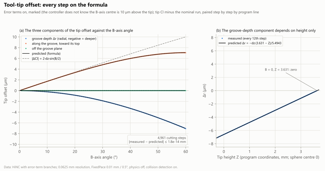
Because the tool axis keeps 48.6° to the sphere's normal, the groove-depth component depends on the tip height alone: Δr = −dz·(3.631 − Z)/5.4943, 0 at the groove top and deeper toward the equator, within 0.0003 µm over the 4,250 steps of the five-axis blocks. On the part, read as the signed distance of every vertex of the cut with the error to the nominal cut, the groove floor's median is −6.45 µm at the four groove ends, −4.88 µm at B ≈ 50°, −3.20 at 40°, −1.79 at 30°, −0.82 at 20°, −0.21 at 10° and −0.03 µm at the top. The prediction vertex by vertex, the nominal cutter moved rigidly by each step's ΔCl, lies within 0.1 µm of these medians, and in 31 bins along the height the floor medians lie within 0.29 µm of the plan's formula. The deepest point at the groove ends reads −7.33 µm against the design's −7.0 µm. The groove widens too, by 5.86 |Δr| as derived from its face angles, about 41 µm at the ends; the 0.0625 mm mesh shows only the trend.
Nothing else moved. The two pits come as close to the sphere centre as without the error, 3.63084 and 4.52138 mm, and 99.91 % of their 13,784 vertices lie within 0.5 µm. So do 99.999 % of the uncut sphere's vertices, the patch missing in the nominal mesh left out, and all of the stem's and the foot's. Over the whole cut without the patch, 98.5 % of 235,812 vertices lie within 0.5 µm, and everything off 0 lies in or beside the two grooves; the lowest, −19.42 µm, sits on the bottom crease of groove B, checked with an exact distance. The program's own fault, the pits at B ≈ 0, and the machine's, a groove depth that grows with B, leave different fingerprints on the same sphere.
The control run, error terms off with a Diff, is the nominal run played again: the tool tip, the machine coordinates and whether each step touches the stock are identical over all 16,018 steps, and its 235,904 vertices within 5.0×10⁻¹⁰ mm of the nominal cut. The spindle the agent added did not change the cut. The evidence is not the control run, since both runs carry the change, but the pits: 3.63084 and 4.52138 mm in the nominal cut, the same as the base case's 3.6308 mm on sim1 and 4.5214 mm on sim2, the authors' program that repeats sim1's lines 844–845 at its lines 288–289.
With the mark cleared, as a controller with calibrated kinematics would know the error, the switch still on and the same G54 typed, the trimmed run cut the same part: the machine coordinates of all 3,037 paired steps equal the marked run's bit for bit, the tool tip lies within 1.8×10⁻¹⁵ mm, the file of mesh distances of the cut is identical byte for byte, and HiNC's Diff statistics match. The program is in machine coordinates, with no G43.4, no G68 and no CL, so the controller sends the program plus the work offset straight to the axes; knowing the error, it has nothing to correct. The only difference is line 16, a C positioning in the air from C0 to C144.756 with the tip 14.7 mm off the C axis: 2,806 steps unmarked against 2,807 marked, with the same end points. HiNC's motion resolution, 0.01 mm and 0.5° here, divides a line into the larger of its tip chord over 0.01 mm and its turn over 0.5°, and the tip here is the one the controller computes itself: on the nominal chain, marked, 14.7247 mm from the C axis, a chord of 28.0674 mm and 2,807 steps; with the error, unmarked, 14.7162 mm, 28.0514 mm and 2,806 steps. Both counts agree, an agreement read from the numbers, not traced in the code.
To put the tip back on the program, a post-processor would have to write every block as X′ = X + dz·sin B and Z′ = Z − dz·(1 − cos B), with the touch-off G54: +8.66 and −5.0 µm at B 60°. That is derived from the formula, not played. The other way is to set the tip back on the B axis. A calibrated controller only comes into play with an RTCP program.
The study models one constant error only, the tip off the B axis along the tool. A real B head has others at the same time: the tip off the axis across the tool at B 0, which would move the groove ends and take the grooves out of their planes, so that the depth no longer follows the height alone; a tilt of B; a run-out of C. A spindle growing with heat would make dz change with time, which a constant error term cannot hold. The size and the sign were chosen: 10 µm is typical, not measured. Per micrometre of dz the groove ends go 0.70 µm deeper, and with the tip above the B centre every sign turns, the grooves getting shallower toward the equator with 7 µm of material left at the ends. The touch-off was typed in and assumed at B 0. T01 and T04 have the same length here; a real second tool brings its own length error. The plays are geometry only, with no cutting force, deflection or heat, and the authors' fixed programs were not played. Everything is simulated; no sphere was cut.
What it brought
- For a machining engineer: a B-head five-axis program in machine coordinates without RTCP stakes its accuracy on one assumption, the tool tip exactly on the B axis. With the tip 10 µm low, each groove is cut deeper from its top toward the equator, 7 µm more at its ends: 28 % of this program's nominal 25 µm depth of cut. A touch-off at B 0 does not see it, and the machine's X, Y, B and C do not change; Z changes only by the 10 µm the touch-off takes in. Its fingerprint is a depth that follows the height alone: measuring the groove depth against the height on the part checks for it and reads dz back. A calibrated controller cannot help, since the program never goes through the machine's chain: marked or unmarked, the machine coordinates are identical bit for bit. The correction belongs in the post-processor, X′ = X + dz·sin B and Z′ = Z − dz·(1 − cos B), or in setting the tip back on the B axis; calibrated kinematics only act on an RTCP program. The program's own fault, the pits at the pole, and the machine's, the depth growing with B, leave different fingerprints on one sphere, and the simulation tells them apart. In HiNC, a constant error measured on a machine can go into its model, to see its shape and size on your own part before anything is cut.
- For a teacher or a student: how an offset on the tool side, dz along the tool, becomes the tip offset dz·(a(0) − a(B)), a(B) being the tool's direction, which the C table then turns, and why it depends on B alone; why a translation upstream of B leaves nothing on this machine; why a tool axis at a constant 48.6° to the sphere makes the depth error follow the height, Δr = −dz·(3.631 − Z)/5.4943; why a mesh distance reads each face along its own normal, 0.97 Δr on the floor, 0.71 Δr on the wall and Δr only at the deepest point; and how marked and unmarked stand for a controller without and with calibrated kinematics, identical on a machine-coordinate program but for a step count set by the controller's own tip.
- For someone deciding whether to use an agent with HiNC: the build and six plays took 1 h 35 min of server time and at most 3.67 GB of memory. The predictions were written before the first play and met to 1.8×10⁻¹⁴ mm on the tool tip, within 0.29 µm on the floor medians, and with the pits where the base case had them; a vertex-by-vertex model added after the plays, the cutter moved rigidly by the measured ΔCl, meets the floor medians within 0.1 µm. Where the plan missed, the record says so as measured: the pairing by program line, the zero offset at B = 0 that holds only once the typed G54 is in effect, the one step fewer on line 16, the wall that cannot take the floor's formula, and a patch missing from the nominal mesh.
Read the full case record: the sphere V-grooves with the tool tip 10 µm below the B axis
How the machine, the stock and the cutter were derived from the NC alone is told in that record; the base case has no page of its own.