NIST cone frustum, C axis 10 µm off-centre: an uncalibrated controller cuts most of the cone up to 18 µm too deep, yet a roundness check at mid-height reads only 3 µm; a calibrated one cuts the nominal part (5-axis)
- Original source
- S. Moylan, D. Blumenfeld, M. McGlauflin, R. Fesperman, M. A. Donmez (NIST and Pennsylvania College of Technology), Evaluation of Proposed Test Artifacts for Five-Axis Machine Tools, Proceedings of the ASPE 2011 Annual Meeting, vol. 52, pp. 520–523 — tsapps.nist.gov, publication 909384. The size of the error is the one the paper reports on p. 523.
- Search keywords
Moylan "Evaluation of proposed test artifacts for five-axis machine tools",NIST cone frustum truncated square pyramid five-axis- Licence
- Official contribution of the National Institute of Standards and Technology (NIST); not subject to copyright in the United States (the paper's own footnote; see NIST's copyright statement). This page reproduces no figure of the paper. Every picture is a HiNC capture.
- Attribution
- Artifact dimensions and cutting conditions after Moylan et al., National Institute of Standards and Technology (NIST), ASPE 2011. NIST does not endorse this case, HiNC, or any product used here. The base case made the part, its stock, the toolpath and the program from the paper's drawings and cutting conditions, and chose the fixture and the generic B/C machine itself. Tech Coordinate's agent added the error. Its size is the paper's. Where it sits, its sign and the typed work offset are the agent's choices.
- About the case
- This case takes the accepted cone-frustum program of the
NIST five-axis test artifacts. The Ø200 mm frustum
sits tilted 10° on the rotary table of a generic B/C table-table machine. The side of a Ø12.7 mm end
mill finishes its cone, under a Fanuc
G43.4(RTCP) program that HiNC wrote from the agent's cutter locations. Here that machine gets the error the paper names for the machine that cut its frustum: the C axis turns about a centre 10 µm off in X (EX0C in ISO 230-7). The paper gives no sign, so the agent took +X.
The story
The frustum's set-up had already passed its acceptance. Its program has 5,333 lines in seven passes round the cone. B swings between −25° and −5° while C winds about seven turns, so all five axes move while the side of the cutter finishes the cone.
The NIST authors traced the errors they measured on their frustum to the machine that cut it: "previous measurements on this machine indicate a location error of the C′-axis in the machine's X-direction of approximately 10 µm" (p. 523). An AI agent gave the case's machine that same error. The error sits on a branch of the machine marked as an error term, directly upstream of the C axis. The controller solves its axes as if that branch were not there. The simulated machine, though, moves and cuts with it whenever the project's Enable Error Terms switch is on. The agent changed no line of the program.
Before the first play, the agent wrote down the tool-tip offset it expected and the deviation it expected round the cone. It checked the set-up in three whole-program plays at 1 mm. Then it played the whole program at 0.25 mm four times, geometry only:
- error terms off: the nominal cut, which every comparison is measured against;
- off again, with HiNC's geometry difference against the nominal cut: the noise floor;
- on, with the controller unaware of the error, like a controller with uncalibrated kinematics;
- on with the mark cleared, so the controller knows the error, like a controller with calibrated kinematics.
In the two runs with the error on, the agent typed the work offset that a touch-off at B = C = 0 would find: G54 X 50.010 instead of the case's X 50.
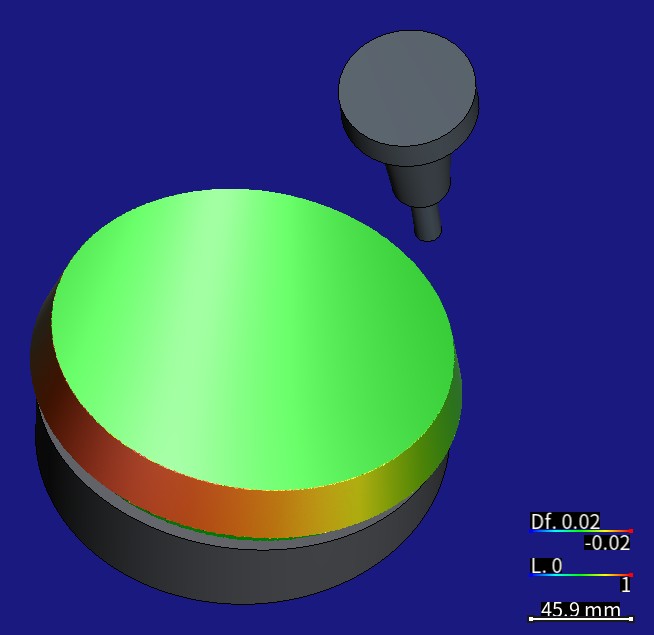

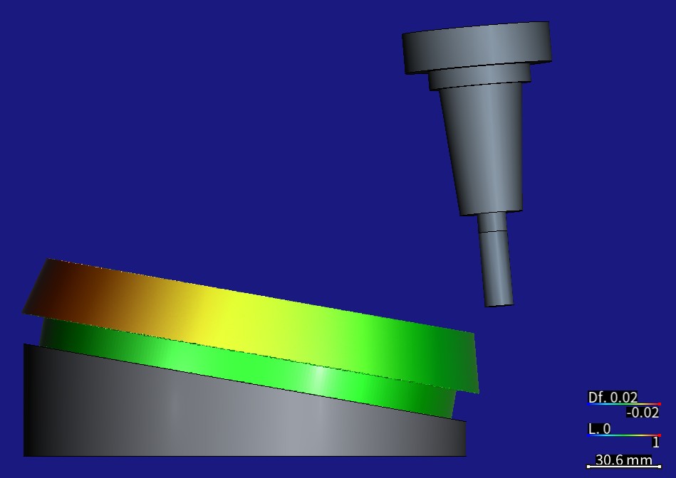
HiNC rendered the part pictures at 0.25 mm. The models are the ones the base case's agent drew after the drawings of Moylan et al. (NIST). The colours are HiNC's geometry difference (Df in the colour bar) against the part the nominal run cut, on a symmetric scale of ±0.02 mm: red = cut too deep, blue = material left, green = 0.
| Key number | What it is |
|---|---|
| 10 µm | the error: the C axis turns about a centre 10 µm off in +X from the one the controller assumes (EX0C in ISO 230-7). The size is the one the paper reports for the machine that cut its frustum. The sign is the agent's choice. The runs with the error typed G54 X 50.010, the offset a touch-off at B = C = 0 would find |
| 1.14×10⁻¹³ mm | the largest gap, over all 35,513 cutting steps, between the measured tool-tip offset and the formula written before the first play: δ = (d(1 − cos C), −d·sin C, 0), with d = 10 µm. That gap is effectively zero. The offset itself is 0 at C ≡ 0 and 20 µm at C ≡ 180°, whatever B and the linear axes do |
| −18.1 µm | the deepest point, on the cone's −X side, which is cut at C ≡ 180°: −18.126 µm measured and −18.126 µm predicted. The surface normal there lies 25° from horizontal (the cone's 15° half-angle plus the 10° tilt), so the surface keeps 2d·cos 25° of the 20 µm offset |
| 272.5° | how much of the cone's circumference is cut too deep. The angle is measured round the part's axis from its +X side. The cut is too deep from ±43.73° (the formula gives 43.76°) all the way round the −X side. The +X side, cut at C = 0, does not move. At ±25.5° on either side of it, up to +1.0 µm of material is left. Round the whole cone, the measured median per 2° stays within 0.011 µm of the prediction |
| 2.98 µm | the roundness that a check at mid-height reads: only 16 % of the largest radial deviation, 18.77 µm. The same least-squares circle is 16.25 µm smaller in diameter, and its centre has moved 10.26 µm towards the part's +X side |
| 1.28×10⁻¹³ mm | the farthest the tool tip moves from the program, from step 86 on, when the controller knows the error. That run cuts the nominal part. Its B and C positions are identical to the nominal run's, bit for bit. X, Y and Z differ by up to 20 µm from where the uncalibrated controller with the same touch-off puts them |
| 20 min | of time on the shared 32-thread server for the eight plays, 37,020 steps each: three at 1 mm, four at 0.25 mm and one more for the holder pictures. A 0.25 mm play took 185–195 s and at most 5.61 GiB of memory |
Four of its seven dilemmas
What a touch-off would have found
With a single translation in front of the C axis, the error shifts the table even at C = 0. A shop that touches off at B = C = 0 gets a G54 that absorbs that 10 µm. HiNC measures program zero on the nominal machine, so it absorbs nothing. With the case's own G54, even the side cut at C = 0 would come out 10 µm off. The agent worked out from the machine chain what the touch-off would find, G54 = (50.010, 0, −55.7418). It typed that in, as HiNC's manual recommends for reproducing a shop's result. The 14 programmed steps at C ≡ 0 then lie within 5.1×10⁻¹⁴ mm of the nominal tool tip.
10 µm on a 0.25 mm grid
10 µm is 4 % of a 0.25 mm grid cell, and the deepest deviation, 18 µm, is 7 %. The designer agent expected the error to sink below the voxel noise. It proposed showing the error fifty times larger, and the plan kept such a run in reserve, for the pictures only. A 0.25 mm trial on another error-term case had already shown that the cut mesh's distance follows the error, readable down to ±2.7 µm. This case's mesh read the predictions directly. Over all its vertices, two stray ones aside, the 1st percentile is −18.04 µm against the predicted deepest −18.1 µm, and the 99th +0.95 µm against the predicted most material left, +1.0 µm. Every number and picture here shows the real 10 µm; the fifty-times run was never played.
86 steps off the formula, all in the air
The plan's criteria asked for a check on every step. In both runs with the error, the first 86 steps were up to 10.0 µm off the formula. Step 0 is the tool-change position of T1 M06, a fixed machine position, (0, 0, 600, 0, 0), that the typed 10 µm cannot move. Steps 1 to 86 are the first G00, moving out from that position, and the gap falls to 0 when the move reaches the first programmed point. G43.4 is already on from line 9, the line before that G00, so RTCP is not the cause. None of these steps touches the stock. One more check took each run's own machine coordinates through the nominal machine's kinematics, removed the typed G54 and added δ. It reproduces all 37,020 tool tips, these 86 included, within 8.0×10⁻¹² mm. The record marks the two criteria as not met as written and checks the cutting steps separately.
A prediction against the wrong run
The plan predicted that a controller that knows the error would move X, Y and Z up to 20 µm away from the nominal run. Measured step by step, from step 86 on, every step was exactly 10 µm away: the C axis's true position, turning with B. The difference of up to 20 µm appears only against the uncalibrated run, which typed the same touch-off G54 X 50.010; the nominal run kept X 50. The plan's sentence came from an earlier design in which all four runs used one work offset. The record keeps the miss and gives each of the three comparisons its own formula. All three hold within 1.4×10⁻¹³ mm.
The other three are in the full record. The case's own stock record would have fed a 1 mm stock into the 0.25 mm runs. A replay made for the holder pictures started from a part already cut. And two vertices read −164.5 µm, a value the cut did not cause.
The result
All eight plays ran to the end, 37,020 steps each, with no collision, no rapid move through stock and no travel alarm.
With the controller unaware of the error, the tool tip of each of the 35,513 cutting steps sat where the formula written before the first play put it, within 1.14×10⁻¹³ mm. The offset is 0 at C ≡ 0 and 20 µm at C ≡ 180°. It depends on C alone: not on B, not on the linear axes, and not on the 50 mm between the part and the C axis.
On the part, each point keeps only the component of that offset along the surface normal. Angles here are measured round the part's axis from its +X side. The side at 0°, cut at C = 0, did not move. At ±25.5° the tip is already about 10 µm off, but most of that offset slides along the surface: only +1.0 µm of material is left. At ±43.73° the sign turns. From there, the cone is cut too deep all the way round the −X side, about 272.5° of the circumference. The deepest point is at 180°: −18.13 µm, as predicted. The measured median per 2° stays within 0.011 µm of the prediction computed from each step's C. The top face, the ring under the cone and the pedestal did not change: they stay within ±0.002 µm beyond 0.1 mm from the cone's edges.
The paper notes that the draft standard of the time asked only for the roundness of the frustum's machined surface, and that its authors measured each part at about mid-height (p. 522). Done the same way on the cut, the circle at a height of 12.7 mm gives these numbers. The least-squares circle is 16.25 µm smaller in diameter, and its centre has moved 10.26 µm towards the part's +X side. Yet the roundness reads only 2.98 µm, 16 % of the largest radial deviation of 18.77 µm. The paper's own 10° frustum shows the same pattern. On the CMM it was 7 µm out of round. On the ballbar it was 6 µm out of round, with the trace's centre about 12 µm off (pp. 522–523). That was another machine, with other errors, so only the pattern compares, not the size.
With the mark cleared, the controller knows the error, and under G43.4 it compensates with the linear axes. From step 86 on, the tool tip stayed within 1.28×10⁻¹³ mm of the program. The cut equals the nominal part within 0.0005 µm, two stray vertices aside. B and C did not change at all. X, Y and Z differed by up to 20 µm from where the uncalibrated controller with the same touch-off put them. The control run repeated the nominal run step for step, and its geometry-difference pictures read within ±1 µm.
The study models this one error only. The paper gives no sign. With the error in −X, the same shape would come out as material left, of the same size. The machine is the case's orthogonal B/C machine, not the paper's machine, whose B′ axis is inclined 45° from Y. The plays are geometry only, with no cutting force or deflection. Everything is simulated; no part was cut.
What it brought
- For a machining engineer: a C axis only 10 µm off-centre makes a simultaneous five-axis frustum come out up to 18 µm too deep on the side cut at C ≡ 180°. The side cut at C = 0 does not move. A touch-off takes out the error only at the pose where it is made. A roundness check alone reads 3 µm and misses most of the error, which shows in the diameter and the centre. A controller with calibrated kinematics, whose RTCP knows where the C axis really is, takes out the whole error. Only X, Y and Z change, by up to 20 µm against an uncalibrated controller with the same touch-off. In HiNC, a constant error measured on a machine can go into its model. The model then shows what the error does to your own part, and how much, before anything is cut.
- For a teacher or a student: how a rotary axis's location error becomes the tool-tip offset δ = (I − R(C))·d. Here d is the 10 µm centre offset, R(C) is the rotation by the C angle about Z, and I is the identity. Why that offset does not depend on how far the part sits from the axis. Why a surface keeps only the normal component of the offset: at ±25.5° the tip is about 10 µm off, but the surface moves only 1 µm. Why roundness alone shows 16 % of the largest error, the very pattern the paper saw on its 10° frustum. Marked and unmarked branches as uncalibrated and calibrated kinematics. And how a real touch-off differs from HiNC's program zero, which is measured on the nominal machine.
- For someone deciding whether to use an agent with HiNC: the study went from the accepted program to one machine error's effects in eight plays and about 20 minutes of server time, at most 5.61 GiB a play. The predictions were written before the first play. They held within 1.14×10⁻¹³ mm on the tool tip, within 0.03 µm for the deviation table and within 0.05 µm for the circle's numbers. Two of its predictions missed, and the record gives what was measured: which run the calibrated controller's machine coordinates should be compared with, and a "crescent" that in fact runs most of the way round.
Read the full case record: the NIST cone frustum on a C axis 10 µm off-centre
How the frustum, its toolpath and this program were made: NIST five-axis test artifacts.