Forged aluminium wheel, 17 inches: with the C table 20 µm off-centre, an uncalibrated controller thins every spoke by about 40 µm and shifts the bolt circle 36 µm; a calibrated one cuts the nominal wheel (3+2 / 5-axis)
- Original sources
- Numbers only, no model: ANKUSI Open Wheel Fitment Dataset: bolt pattern, centre bore and OE wheel specifications for 7,603 vehicle variants, ANKUSI Wheels engineering team, figshare, version 4, 2026 (doi:10.6084/m9.figshare.33921994); the height of a J rim flange, 17.3 mm, from the German Wikipedia article Autofelge.
- Search keywords
ANKUSI Open Wheel Fitment Dataset,figshare 33921994,Autofelge Form J- Licence
- The data set is under CC BY 4.0; only three of its numbers are used. The wheel, its toolpaths and programs, the machine and its error are the agent's own: no wheel maker's model or drawing is used, the case names no vehicle, and the error's size and sign are not a measurement of any machine.
- Attribution
- Wheel size numbers from the ANKUSI Open Wheel Fitment Dataset (ANKUSI Wheels engineering team, figshare, doi:10.6084/m9.figshare.33921994, CC BY 4.0). Wheel design by Tech Coordinate's agent.
- About the case
- The accepted face-up programs of the 17-inch forged aluminium wheel: four five-axis Fanuc programs on a generic table-C / swivel-head-B machine. Here that machine gets one constant geometric error: its C table turns about a centre 20 µm off in +X (EX0C in ISO 230-1 / 230-7). That is a typical size the agent chose; nobody measured this generic machine.
The story
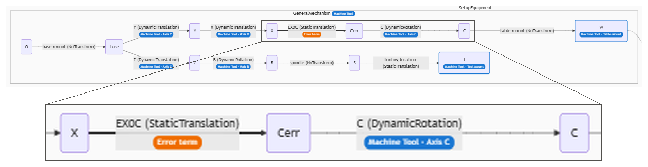
The wheel's face-up set-up had already passed its acceptance: four five-axis Fanuc programs with RTCP (G43.4) that HiNC wrote from the agent's cutter locations. The 20 mm roughing tool works at C 0. The 12 mm flank cutter finishes the 7° drafted window walls at B −7°, with C turning to follow the walls. The drill and the seat cutter both work at C −3366°, the same table angle as 234°. An AI agent then gave the machine one common geometric error: its C table turns about a centre 20 µm off in +X from the one the controller's kinematics assume. The error sits on a branch of the machine marked as an error term, directly upstream of the C axis. The controller solves its axes as if that branch were not there, while the simulated machine moves and cuts with it whenever the project's Enable Error Terms switch is on. The agent changed no line of the programs. It wrote down the tool-tip offset and each feature's deviation it expected, checked the set-up in two whole-wheel plays at 1 mm, and then played the whole wheel at 0.5 mm four times, geometry only:
- error terms off: the nominal cut, which every comparison is measured against;
- off again, with HiNC's geometry difference against the nominal cut: the noise floor;
- on, with the controller unaware of the error;
- on with the mark cleared, so the controller knows the error, as a controller with calibrated kinematics would.
The two runs with the error typed the work offset that a touch-off at C 0 would find, G54 X 0.020.
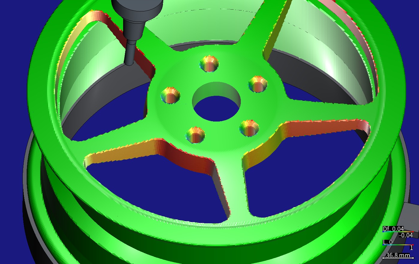
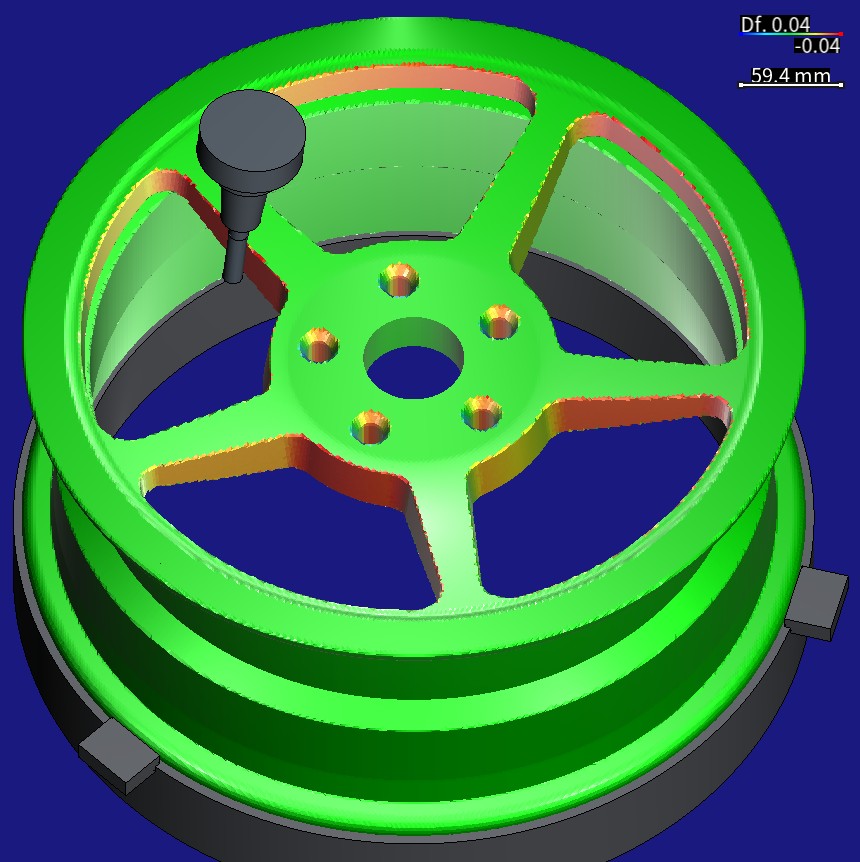
HiNC rendered these pictures from the wheel Tech Coordinate's agent designed, not from a wheel maker's design file. The colours are HiNC's geometry difference (Df in the colour bar) against the wheel the nominal run cut, on a symmetric scale of ±0.04 mm: red = cut too deep, blue = material left, green = 0.
| Key number | What it is |
|---|---|
| 20 µm | the error: the C table turns about a centre 20 µm off in +X from the one the controller assumes (EX0C in ISO 230-1 / 230-7). It is a typical size the agent chose, not a measurement. The runs with the error typed G54 X 0.020, the offset a touch-off at C 0 would find |
| 1.6×10⁻¹³ mm | the largest gap over all 157,412 cutting steps between the measured tool-tip offset and the formula written before the first play. That gap is effectively zero. The offset itself: 0 for the roughing at C 0, up to 40 µm for the flank, (31.8, 16.2) µm for the holes and seats |
| −39.7 µm | the one flat window wall facing −X, spoke 0's side towards window 0: −39.686 µm measured, −39.685 µm predicted. The walls facing +X do not move |
| 38.2–41.3 µm | how much thinner each of the five spokes comes out; measured and predicted agree within 0.02 µm. It looks as if the cutter radius were 20 µm larger |
| 35.6 µm at 27° | how far the five bolt holes and seats moved, as one set, off the turned centre bore: 35.63 µm at 26.96° measured, 35.64 µm at 27.0° predicted. The distance between holes changes by 0.14 µm at most |
| 4.9×10⁻¹² mm | the farthest the tool tip moves from the program when the controller knows the error. That run cuts the nominal wheel; only its machine X positions differ, 20 µm larger on every cutting step |
| 32 min | of server time for the build and the six whole-wheel plays (183,870 steps each; two at 1 mm, four at 0.5 mm). One 0.5 mm play used at most 17.8 GiB of memory |
Four of its six dilemmas
What a touch-off would have found
A shop sets up a wheel like this by probing the centre bore, here assumed at B = C = 0. The G54 it finds absorbs the 20 µm the error pushes the table. HiNC measures program zero on the nominal machine and absorbs nothing, so with the case's own G54 even the roughing at C 0 would come out 20 µm off. The agent worked out the offset the touch-off would find, G54 X 0.020, and typed it in, as HiNC's manual recommends for reproducing a shop's result. All 130,003 cutting steps of the roughing at C 0 then lie within 9×10⁻¹⁴ mm of the nominal tool tip.
A prediction against the wrong run
The plan predicted that, compared with the nominal run, a controller that knows the error would move X and Y off along a circle as C turns, up to 40 µm. Measured step by step, the X position was exactly 20 µm larger on every cutting step and Y did not change: the whole motion shifted, and each step's travel stayed the same. The plan's formula came from an earlier design in which every run used the same work offset. With G54 X 0.020 typed, it describes the calibrated controller against the uncalibrated one, within 4.8×10⁻¹² mm. The record keeps the miss and gives each comparison its own formula.
20 µm on a 0.5 mm grid
20 µm is 4 % of a 0.5 mm grid cell, and the deepest deviation, 39.7 µm, is 8 %. The designer agent expected the error to sink below the voxel noise and proposed showing it ten times larger; the plan kept such a run in reserve, for the pictures only. The whole wheel at 0.5 mm read the predictions directly. Each of the ten flat window walls reads within 0.02 µm of its prediction, and the bolt-circle shift reads 35.633 µm against 35.640 µm predicted. Every number and picture here shows the real 20 µm; the ten-times run was never played.
Readings of ±0.6 mm that are not the error
Against the nominal wheel, the cut with the error read from −0.585 to +0.694 mm, more than ten times the deepest predicted 39.7 µm. The agent checked the 2,899 vertices beyond 0.05 mm one by one. 2,856 lie on the turned rim, which no tool of this set-up touches. They read the same value in the run whose cut equals the nominal, so they come from the distance measurement, not from the part. The other 43 sit on the sharp edges of the holes and seats, which have moved 36 µm. The analysis reads them as the 0.5 mm grid rounding those edges differently after the move.
The full record has the other three. Among them are a control run that left no cut of its own to measure and two places where the run notes disagreed with the records.
The result
All six plays ran to the end, 183,870 steps each, with no collision, no rapid move through stock and no travel alarm.
With the controller unaware of the error, the tool tip of each of the 157,412 cutting steps sat where the formula written before the first play put it, within 1.6×10⁻¹³ mm. The roughing at C 0 has no offset. The flank has up to 40 µm, changing as C follows the walls. The holes and seats, cut at C ≡ 234°, have (31.8, 16.2) µm.
On the part, each face keeps only the part of that offset along its normal. The walls facing +X did not move, and the one flat wall facing −X is 39.7 µm too deep. In effect, each window is shifted 20 µm in +X and each of its faces is cut 20 µm deeper. So the five spokes come out 38.2 to 41.3 µm thinner, as if the cutter radius were 20 µm larger. The five bolt holes and their seats moved together 35.6 µm towards 27°, off the turned centre bore; their size and the distance between them did not change. The roughing at C 0, the turned faces, the rim and the spoke fronts did not change.
With the error known to the controller, the tool tip stayed within 5×10⁻¹² mm of the program, and the cut equals the nominal wheel. Only the machine coordinates differ: every cutting step's X position is 20 µm larger than nominal.
The study models this one error only, and the agent chose its size and sign; with the error in −X, every deviation would change sign. The plays are geometry only, with no cutting force or deflection. Everything is simulated; no wheel was cut.
What it brought
- For a machining engineer: a C table only 20 µm off-centre makes every spoke of a five-axis flank-milled wheel about 40 µm thinner. That looks like a cutter radius 20 µm too large, so a thin spoke is not always the tool or its offset. A touch-off takes the error out only at the C angle where it is made. The roughing at C 0 is untouched, but three-axis work at another C angle, here the drilling and seating, still cuts the error in: the bolt circle ends up 36 µm off the centre bore. That work belongs at the touch-off's C angle, or the kinematics need calibrating; a calibrated controller takes the whole error out. In HiNC, a constant error measured on a machine can go into its model, which shows what it does to your own part, and how much, before anything is cut.
- For a teacher or a student: how a rotary axis's location error becomes the tool-tip offset δ = (I − R(C))·d, where d is the 20 µm centre offset, R(C) the rotation by the C angle about Z and I the identity, and why it depends only on C. Why δ looks both like a moved window and like a wrong cutter radius: it is a shift by d plus an extra cut of d along each wall's normal. Why a face keeps only the normal part, so a wall facing +X does not move and the draft multiplies the deviation by cos 7°. Marked and unmarked branches as uncalibrated and calibrated kinematics. And how a real touch-off differs from HiNC's program zero, which is measured on the nominal machine.
- For someone deciding whether to use an agent with HiNC: the study went from accepted programs to one machine error's effects in six whole-wheel plays and 32 minutes of server time. The predictions were written before the first play and matched within 1.6×10⁻¹³ mm on the tool tip and 0.02 µm on the flat walls and spokes. Where the plan missed, as with the calibrated controller's machine coordinates, the record gives what was measured.
Read the full case record: the wheel on a C table 20 µm off-centre
How the wheel, its toolpaths and these programs were made: Forged aluminium wheel, 17 inches.