A 17-Inch Forged Aluminium Wheel on a C Table 20 µm Off Centre: an Uncalibrated Controller Leaves Each Spoke About 40 µm Thinner and the Bolt Circle 36 µm Off, a Calibrated One Cuts the Nominal Wheel
The 17-inch forged wheel is a one-piece 6061 wheel that an AI agent
designed from three public fitment numbers and programmed itself. Its first set-up, OP30, is four Fanuc
G43.4 (RTCP) programs. HiNC wrote them back from the agent's cutter locations, and the case accepted
them on a generic table-C / swivel-head-B five-axis machine:
- T1 roughs the five windows at C 0 the whole time.
- T2 flanks the windows' 7° drafted walls in five axes at B −7°, with C turning to follow the wall.
- T3 drills the bolt holes and T4 cuts their 60° seats. Both stay parked at C −3366°, which is the same angle as 234°.
On this page the agent gives that machine a common geometric error. The real centre of rotation of the C table lies 20 µm in +X from where the controller's kinematic model puts it. ISO 230-1 and ISO 230-7 call this error EX0C. It is modelled as one branch of the machine chain, marked as an error term. Not one line of the programs was changed. The whole wheel was cut four times at a 0.5 mm grid:
- Error terms off: the nominal cut. The geometry differences of the other full runs are measured against it.
- Error terms off again, with the geometry difference: the control run. It measures the noise floor.
- Error terms on, error marked: the controller does not know the error. This is what a controller with uncalibrated kinematics does.
- Error terms on, mark cleared: the controller knows the error. This is what a controller with calibrated kinematics does.
Both runs with the error terms on had G54 X 0.020 typed in: the work offset that a touch-off at C 0 would find on the real machine.
When the controller did not know the error, the tool tip on every one of the 157,412 cutting steps landed where the plan predicted, within 1.6 × 10⁻¹³ mm. The prediction is δ = (d(1 − cos C), −d·sin C, 0) with d = 20 µm. That gives no offset at C 0, up to 40 µm while C follows the walls, and (31.8, 16.2) µm at 234°. The results on the part:
- The wall facing −X came out 39.7 µm too deep. The wall facing +X did not change.
- Each window moved 20 µm in +X and every side of it was cut 20 µm deeper. So the five spokes came out 38.2 to 41.3 µm thinner, as if the cutter's radius were 20 µm larger.
- The five holes and their seats moved together, 35.6 µm towards 27°. The bolt circle is no longer centred on the turned centre bore.
When the controller knew the error, the tip stayed on the program to within 4.92 × 10⁻¹² mm, and the wheel came out the same as the nominal one. Only the machine moved differently: at every cutting step, its X axis stood 20 µm further in +X than in the nominal run. Everything here is simulated; no wheel was cut.
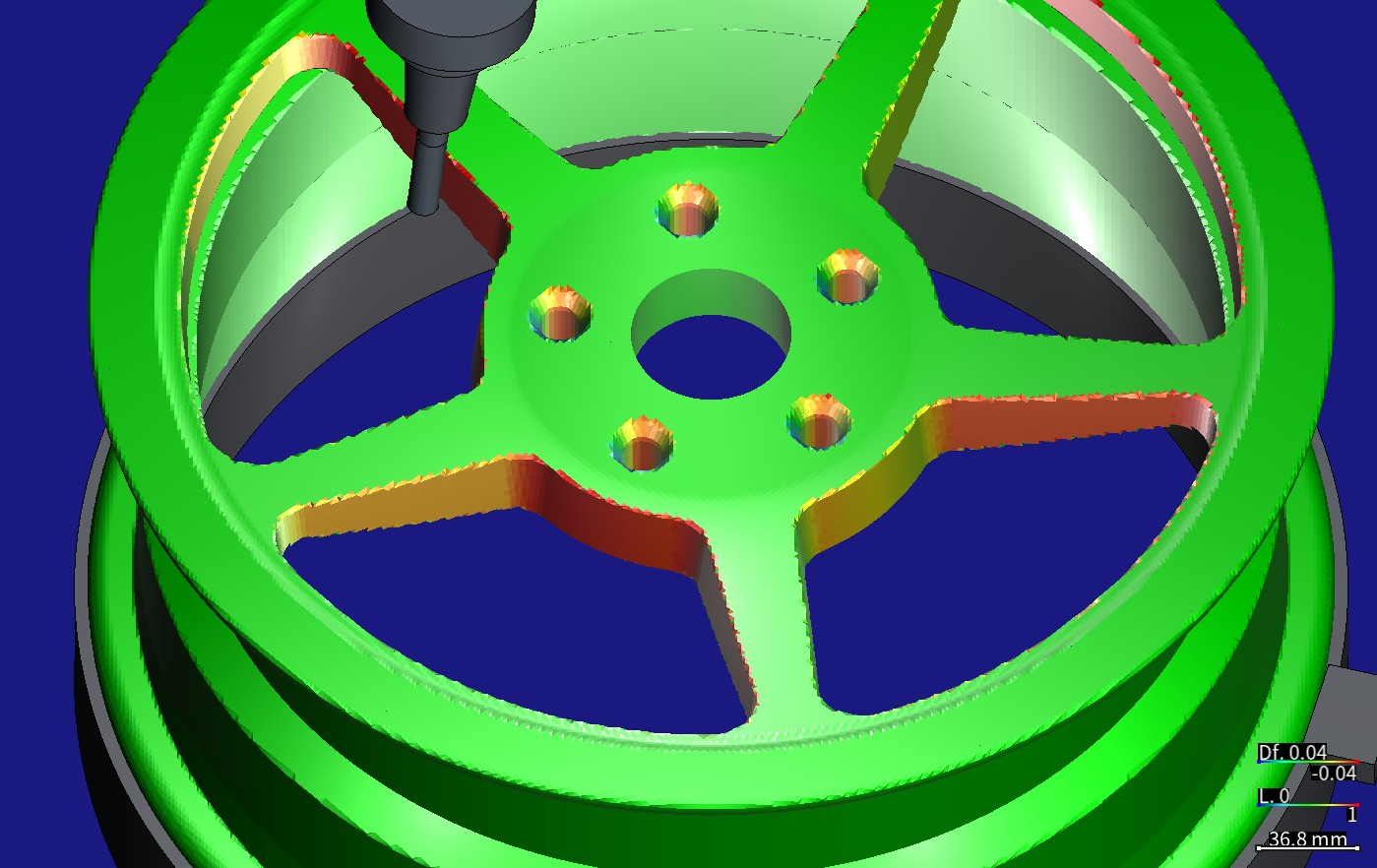
The stock the marked run recorded, put back on the canvas with its geometry difference. A parking program that cuts nothing then stands T2 — the Ø12 mm end mill, 55 mm out of an 80 mm shrink-fit holder — tilted 7° in window 0. Beside the tool, the side of spoke 0 that faces window 0 faces −X and is cut 39.7 µm too deep (red). Each of the five seats is red on the side towards 27° and blue on the other. Colour scale ±0.04 mm: red = cut too deep, blue = material left, green = 0, with both signs weighted alike. Measured on a HiNC 3.2.46 development build with error-term branches, 0.5 mm grid.
| Whole wheel, OP30, at 0.5 mm on a HiNC 3.2.46 development build with error-term branches | Predicted by the plan's formula | Error marked: the controller does not know it | Mark cleared: the controller knows it |
|---|---|---|---|
| How far the tool tip is from the program, cutting steps | δ(C): 0 at C 0, up to 40 µm while C follows the walls, (31.8, 16.2) µm at 234° | on δ to within 1.58 × 10⁻¹³ mm on all 157,412 steps; at most 0.040 mm (T2), 0.036 mm (T3, T4) and 8.99 × 10⁻¹⁴ mm (T1) | within 4.92 × 10⁻¹² mm |
| Window wall facing −X, median deviation | −39.685 µm | −39.686 µm | 0 (below 10⁻⁶ µm) |
| The five spokes, width change | −38.16 to −41.25 µm | −38.17 to −41.25 µm | 0 |
| The five bolt holes, centre shift | 35.64 µm towards 27.0° | 35.63 µm towards 26.96° | 0 |
| Turned faces, rim and spoke fronts | 0 | unchanged: the 5,653,587 turned-face vertices that have a counterpart lie at the same distances as with the mark cleared | unchanged |
| Machine X and Y compared with the nominal run, cutting steps | with the mark cleared, (20(1 − cos C), 20·sin C) µm, as the plan wrote (dilemma 2) | the typed G54 X 0.020, turning with C | X +20.000 µm on every step, Y and Z 0 |
| Server time and peak memory of the run | — | 350.3 s, 17.69 GiB | 350.4 s, 17.80 GiB |
The case
The wheel's own case page tells how the agent designed the wheel, wrote
its toolpaths, and had HiNC write and replay the G43.4 programs. This page starts from the accepted
first set-up. What the agent was given:
- The accepted project and its programs. The OP30 project has the wheel face up. Program zero sits
on the wheel's axis in the mounting face, with +Z pointing outward, and G54 is (0, 0, −506.45). There
are four programs. Their line counts and their B and C values were read from the NC by the designer
agent, the agent that drafted this study:
- T1, a Ø20 mm end mill, roughs the five windows in 30,992 lines. It runs at B 0 and C 0 the whole time and leaves 0.5 mm on the walls.
- T2, a Ø12 mm end mill, flanks the 7° drafted walls in 9,404 lines: a 0.4 mm semi-finishing pass, then the final pass. It runs at B −7°, and C turns from −54° all the way to −3366°.
- T3, a Ø15 mm drill, and T4, a Ø25 mm 60° countersink, both work at B 0 and C −3366°.
- HiNC's error terms. An axis or the spindle of the machine chain can be given an error term, a static branch of its own just before the axis's branch. The
controller is
XyzabcSolver, which turns NC and cutter locations into machine coordinates, RTCP included. It always solves on the nominal chain: the same chain with every marked branch left out. While the project's Enable Error Terms switch is on, the simulated machine keeps the branch in place when it moves, cuts and checks collisions. So the error is cut into the part, as on a real machine whose controller does not know it. With the mark cleared, the controller takes the branch into account, and under RTCP that is a controller with calibrated kinematics (Error-Term Branches). - Touch-off and P0. A single translation upstream of the C axis moves the table by the error even at C = 0. On a real machine, the G54 found by touching off already contains that shift. HiNC's P0 measures on the nominal chain, so it does not. To reproduce a real machine's result, the manual recommends typing in the work offset a touch-off would find (Work offsets on a machine with error terms).
- The request. HiNC's product owner asked for showcases of HiNC's error terms built on accepted cases, from both product cases and paper cases, with the heavy runs on a shared server.
What nothing states:
- How far this machine's C-table centre is off, and in which direction. The machine is a generic one built for these case studies, so there is no measurement to cite. The agent took 20 µm, a typical size for the location error of a rotary axis, and chose +X as the direction.
- The G54 a touch-off would find. The agent derived it from the chain. Suppose the real machine probes the centre bore at B = C = 0 to set G54 X and Y, which is common for wheels. It would then find (0.020, 0, −506.45).
- Whether a 0.5 mm grid can show the error. 20 µm is 4 % of a cell, and the deepest deviation, 39.7 µm, is 8 %.
- That the bolt holes move too. The drilling and seat programs run at C −3366°, the angle where T2 ends. Only reading the NC shows this.
What the agent built
Each value is marked read (from the base case or the documentation), derived (computed from what was read) or chosen (the agent's decision).
| Item | Value | Source |
|---|---|---|
| What the error is | The real centre of rotation of the C table lies off its design position in +X. The design position is the one the controller's kinematic model uses. In ISO 230-1 and ISO 230-7 this is EX0C, the location error of the C axis' average line in the X direction | chosen: the kind of error and its sign; derived: the ISO name |
| Size | 0.020 mm, in the coordinates of the X anchor. On this machine the X anchor's axes are the machine's axes | chosen: a typical size for a rotary axis' location error; this generic machine was never measured |
| Where it sits | Directly upstream of the C axis branch. This machine's C table rides on X, so a new anchor Cerr splits the segment X→C in two. The first part, X→Cerr, is named EX0C, carries a Static Translation (0.020, 0, 0) and is marked as an error term. The C axis' Dynamic Rotation (rotation axis (0, 0, −1), pivot (0, 0, 0)) moves whole onto Cerr→C, and Axis C is bound to it again with its values unchanged |
chosen, following the owner's ruling of 2026-10-06 (dilemma 1) |
| Machine chain | [O][base][Y][X][Cerr][C][w];[base][Z][B][S][t] |
read back after the build |
| Work offset | G54 = (0.020, 0, −506.45) in the two runs with the error on, which is what a touch-off would find; the case's own (0, 0, −506.45) in the nominal and control runs | derived |
Why the C table's centre, and not an offset of the B head's pivot? The designer agent compared the two:
- OP30 uses only B 0 and B −7°. An offset of the B pivot would shrink to about 12 % of its size at B −7°, and it would be the same on every window wall. T1, T3 and T4 would not feel it at all.
- These programs use C in three ways: parked at C 0, turning with the wall, and parked at 234°. One error gives three different results on one part.
- The programs use
G43.4. Only under RTCP does a marked error (an uncalibrated controller) cut differently from an unmarked one (a calibrated controller).
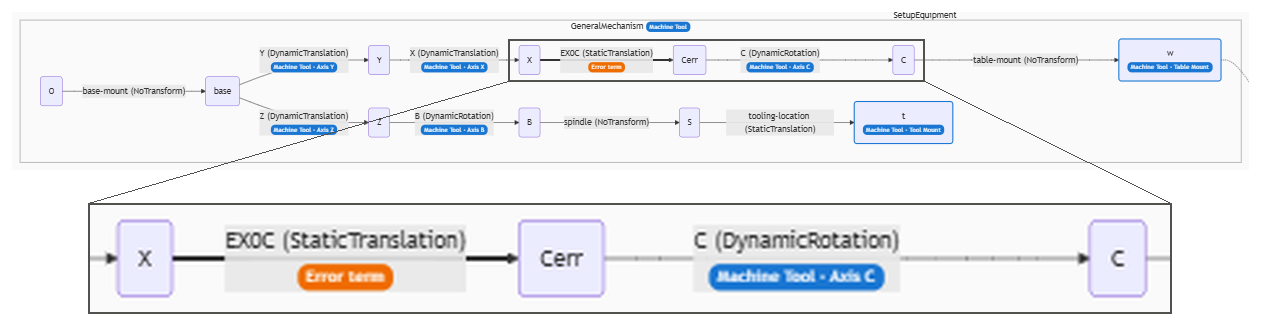
The machine cluster (GeneralMechanism) in the Topology column of the Equipment page. A new anchor, Cerr, now sits between X and C. EX0C, a Static Translation from X to Cerr, is drawn thick and carries the orange Error term badge. The C axis' Dynamic Rotation now runs from Cerr to C and still plays Axis C. Below the graph, the X → Cerr → C stretch of the same capture is shown magnified. A HiNC 3.2.46 development build with error-term branches, English interface.
Where the tip goes: the prediction written in the plan. The controller assumes the table turns about its design centre. In fact it turns about a centre d = 20 µm away. At C = 0, the extra distance d the table moves is already contained in the touched-off G54, so the tip lands on the program. At any other C, the part has moved further than the controller thinks. In program coordinates, the tip is off by
δ = (I − RZ(C))·d = (d(1 − cos C), −d·sin C, 0).
Its length is 2d·|sin(C/2)|, which is largest, 40 µm, at C ≡ 180°. δ depends only on C. It does not depend on B, on the tool length, or on where the point lies on the part. How far a surface moves is the part of δ along that surface's normal:
- T1 roughing: C is 0 throughout, so δ = 0. T1 leaves 0.5 mm for T2 in any case, so no face of the finished part comes from T1.
- T2 flank milling: C equals φ, the direction (azimuth) of the wall's normal pointing into the window. So the deviation along the normal is cos 7°·d·(cos φ − 1). That is 0 on a wall facing +X and −39.7 µm on a wall facing −X (negative = cut too deep). δ can be split into two terms, δ = (d, 0) − d·(cos φ, sin φ). The first term moves the whole window by d in +X. The second cuts every side d deeper, as a cutter radius d too large would. So each of the five spokes loses 38 to 41 µm, and spoke 0 loses all of it on its window-0 side.
- T3 drilling and T4 seats: here C ≡ 234°, so δ = (1.588, 0.809)·d = (31.8, 16.2) µm. That is 35.6 µm long, pointing at 27°. The five holes and seats move as one set, and the bolt circle moves off the turned centre bore. The pitch and the diameters stay the same. On the 60° seats, the deviation along the normal is ±30.9 µm.
- Turned faces, rim and spoke fronts: 0.
- With the mark cleared, the plan wrote: “machine X and Y move (d(1 − cos C), d·sin C) further, at most 40 µm; the tip returns to the program”. What the machine coordinates actually did is in the results and in dilemma 2.
The runs:
| Run | Grid | Error-terms switch | EX0C | G54 | Purpose |
|---|---|---|---|---|---|
| Nominal, trimmed | 1 mm | off | marked (not in effect) | (0, 0, −506.45) | trimmed: nominal |
| Marked, trimmed | 1 mm | on | marked | (0.020, 0, −506.45) | trimmed: the controller unaware, with the geometry difference |
| Nominal | 0.5 mm | off | marked (not in effect) | (0, 0, −506.45) | exports the cut used as the ideal geometry |
| Control | 0.5 mm | off | marked (not in effect) | (0, 0, −506.45) | the geometry difference, for the noise floor |
| Marked | 0.5 mm | on | marked | (0.020, 0, −506.45) | the geometry difference; exports its cut |
| Unmarked | 0.5 mm | on | mark cleared | (0.020, 0, −506.45) | the geometry difference; exports its cut |
Common to every run:
- Physics off. This case is about geometry only, so cutting force and deflection are outside it.
- Collision detection on, without pausing on a failure. Each step is one spindle revolution.
- The four programs only. The NC entries
op30-t1-rough.cls.nc,op30-t2-flank.cls.nc,op30-t3-drill.cls.ncandop30-t4-seat.cls.ncare on. Every other program entry of the mission is off: the cutter locations, the sector programs, the optimized programs and the parking program. - The geometry difference (Geometry Validation): detection
radius 1 mm, colour scale (
DiffVisualRadius) ±0.04 mm. - The recorded stock. The full control, marked and unmarked runs each recorded their final stock. The pictures put that stock back on the canvas.
How the agent managed the work
- Criteria and predictions first. The plan, its predictions and seven criteria were committed at 20:23:51 on 2026-10-06. The first play started at 20:24:14.
- Trimmed runs first. The whole of OP30 ran at 1 mm with physics off, once nominal and once marked, 183,870 steps each. These runs checked three things: the build, the derived G54 (δ = 0 at every T1 step) and the per-step formula. The designer agent had proposed a 72° sector, with the error enlarged ten times for display. The plan replaced that with the whole wheel at 1 mm and the real value.
- Four full runs, one at a time. These ran at 0.5 mm with physics off and collision detection on. All four ran in turn on one private instance. Before each one, the instance was restarted and the project reloaded from its file. All four ran within one hold of the lock that the studies on the server share. The plan's stop rules were never reached: start only with 50 GB of the server's memory free, and stop a run that passes 40 GB.
- The nominal cut as the ideal geometry. The nominal run exported its cut, 10,923,528 triangles. That became the ideal (target) geometry, with a 1 mm detection radius. The geometry difference then shows only what the error changes, not the marks the toolpath itself leaves.
- NC entries, not cutter-location entries. The NC fixes C, so the result does not depend on the session's history. The cutter-location-to-NC write-back was off, so the error-term project's programs were never rewritten.
- Every number from the records. The agent's analysis script computes the numbers on this page from the run records and keeps each with its source, so the analysis can be run again; the few taken while writing, such as the difference between the unmarked and marked machine coordinates, come from the same per-step series. The features — window walls, holes, seats, turned faces — are picked out with the design geometry of the base case's own wheel script.
- Pictures in both interface languages. Each run's recorded stock was put back on the canvas with its geometry difference, so no run had to be played again for the pictures.
- Where a person stepped in. HiNC's product owner asked for error-term showcases built on accepted cases. The same day, after looking at the interface, the owner ruled that an error term goes only upstream of a role branch, meaning an axis or the spindle. That ruling changed the design from a pair of translations to one translation and a typed work offset (dilemma 1). The error, the predictions and the criteria are the agent's.
The criteria as committed before the first play:
| # | Criterion |
|---|---|
| 1 | Build: the error-term project reopens with no load message; EX0C is a marked Static Translation (0.020, 0, 0) on X→Cerr; Axis C is bound to Cerr→C with the values it had; the roles check is empty; the case's files outside the error-term folder are unchanged |
| 2 | Every run ends Finished with 183,870 steps (the marked run within 1 % of the nominal is also accepted), and contact (IsTouched) peaks at 1; no collision, no rapid cutting, no stroke alarm; runs with a geometry difference add only Diff--TargetNotClosed |
| 3 | Marked: on every T1 cutting step, the tip within 1 × 10⁻⁹ mm of the nominal; on every cutting step, the tip minus the nominal minus δ within 1 × 10⁻⁶ mm; T3 and T4 at δ = (1.588, 0.809, 0)·d ± 1 × 10⁻⁶ |
| 4 | Unmarked: on every cutting step, the tip within 1 × 10⁻⁶ mm of the nominal |
| 5 | Control: at least 99 % of the vertices within 1 µm of the nominal cut |
| 6 | The part, marked against nominal, by vertex distance: (a) the walls facing −X at a median of −39.7 µm ± max(floor, 5 µm); (b) the five spokes' width change −38 to −41 µm ± 5 µm; (c) the five holes' fitted centres shifted 35.6 µm ± 5 µm towards 27° ± 5°; (d) the faces T1 leaves and the turned faces within the floor |
| 7 | Cost: wall time and peak memory (VmHWM) recorded for every run |
The dilemmas
Each one is told as its situation, the risk if it had been missed, how it was noticed, the resolution, and the evidence that the resolution held.
1. A pair of translations, or one translation and a typed work offset
- Situation. The designer agent proposed a translation on each side of C: +d before it
(
Cpiv-offset) and −d after it (Cpiv-return). At C 0 the two cancel, so G54 and P0 need no change, and the four runs differ only in the switch and the mark. It also proposed trimming the runs to a 72° sector, with the error enlarged ten times for display. - Risk. The same day, after looking at the interface, the product owner ruled that an error term goes only upstream of a role branch, meaning an axis or the spindle. The translation after C is not upstream of any role branch. Suppose the agent had used one translation but kept the case's original G54. Then T1, which cuts at C 0, would also be off by 20 µm, and the simulated part would not look like a part from a machine that was touched off.
- How noticed. While writing the plan to follow the ruling. The designer's record is the version from before the ruling.
- Resolution. EX0C goes before C only, on
X→Cerr. The two runs with the error terms on have the touch-off's G54 = (0.020, 0, −506.45) typed in. The nominal and control runs keep (0, 0, −506.45). This gives the same δ as the pair of translations. The trimmed runs became the whole wheel at 1 mm with the real value. - Evidence. All 130,003 of T1's cutting steps are at C 0, and on every one the tip lands within 8.99 × 10⁻¹⁴ mm of the nominal. So the typed G54 is right. On every cutting step the tip meets the formula to within 1.58 × 10⁻¹³ mm, in the trimmed runs and in the full runs.
2. Which run to compare the machine coordinates with: the calibrated X and Y do not trace the plan's circle
Situation. For the unmarked run, the plan predicted “machine X and Y move (d(1 − cos C), d·sin C) further, at most 40 µm”, compared with the nominal run. The manual also says that each step's machine coordinates are the same with the switch on and off.
Risk. Writing the result as predicted would contradict the measurement. So would writing “the marked run's machine coordinates equal the nominal run's”. Reading the difference as a controller fault would be wrong as well.
How noticed. While comparing the three runs' machine coordinates step by step: the nominal run uses G54 X 0, and the two runs with the error use X 0.020.
Resolution. The page states what was measured, and each comparison gets its own formula:
- Unmarked minus nominal is (+20.000, 0, 0) µm at every cutting step. The calibrated controller takes the 0.020 mm it knows about out of the typed G54 X 0.020, so program zero lands on the real C axis. The whole table is 20 µm off, so every point is reached by the nominal motion shifted 20 µm in +X.
- Marked minus nominal is RZ(−C)·(d, 0): the typed G54 turning with the table. The controller cannot see EX0C, so the machine coordinates differ by the work offset alone.
- Unmarked minus marked is exactly the plan's (d(1 − cos C), d·sin C), 0 to 40 µm long.
The plan's sentence came from the paired design, in which all four runs used one G54. With one translation and a typed G54, the sentence describes unmarked minus marked. “The switch does not change the machine coordinates” holds only when the work offsets are the same. Criterion 4 judges the tip, so it is not affected.
Evidence. The residuals of the three comparisons, in that order, are at most 4.7 × 10⁻¹², 1.28 × 10⁻¹³ and 4.8 × 10⁻¹² mm. B and C are the same in all three runs, bit for bit.
3. Whether a real 20 µm error shows on a 0.5 mm grid
- Situation. 20 µm is 4 % of a cell, and the deepest deviation, 39.7 µm, is 8 %.
- Risk. The designer agent expected the error to be lost in the voxel noise, and proposed showing it enlarged ten times. The plan kept a ×10 run in reserve (0.2 mm, G54 X 0.2) for the pictures alone. Pictures from that run would need an explanation of the scaling, and the wheel would need another full run.
- How noticed. The plan set the rule in advance: decide after two results. One was the full result of another error-term case in the same batch, a NIST cone frustum with a real 10 µm error at 0.25 mm. The other was this case's own 0.5 mm result. Both showed the predicted values directly.
- Resolution. No enlargement. Every number and every picture shows the real 20 µm, with a colour scale of ±0.04 mm. The ×10 run was never played.
- Evidence. On the ten flat window walls, the median of measured minus predicted is within 0.02 µm, and 99.999 % of their vertices lie within ±1 µm of the prediction. The bolt circle's shift measured 35.633 µm against 35.640 µm predicted.
4. Extremes of ±0.6 mm that are not the error
Situation. The vertex distances of the marked cut run from −0.585 to +0.694 mm. That is more than ten times the largest predicted deviation, 39.7 µm. The notes taken during the runs called these values measuring artefacts at the edges of machined faces, and asked for the vertex data to be checked before saying so.
Risk. Taken for the error, they would say the part was cut wrong. Set aside without a check, the claim would not stand.
How noticed. The analysis checked, one by one, the 2,899 vertices more than 0.05 mm away.
Resolution. These vertices fall into two groups:
- 2,856 sit on the turned faces of the rim (R 192.39–215.49 mm, the median at R 192.4 on the inside of the barrel), not at the edge of a machined face. No OP30 tool goes there. In both runs that area is the same untouched stock, so its true distance is 0. The unmarked run, which cuts the nominal part, reads the same values on the same vertices. So the cause is the measurement itself, not the error. A likely reason, not checked vertex by vertex: the distance search looks only at the centroids of the 12 nearest triangles. The rim's turned surface is made of long, thin triangles whose centroids lie far from the vertex, so the right face may not be among those 12. The wheel's own case met the same kind of problem on its turned surfaces (dilemma 11, “Checking the checker”, on its page).
- The other 43 sit on the two sharp edges of the shifted holes and seats: the seat's outer edge at z ≈ 30 and the edge where hole and seat meet at z 23.08. They read +0.050 to +0.061 mm, in the marked run only. The analysis reads this as follows: the features moved 36 µm relative to the grid, so the 0.5 mm grid rounds their sharp edges differently.
Every feature fit uses only vertices more than 0.75 mm from an edge.
Evidence. The lowest and highest distances are the same in the two runs.
5. A control run with no cut of its own
Situation. Criterion 5 asks for 99 % of the control cut's vertices to lie within 1 µm, and criterion 6's floor was to come from the control cut.
Risk. As written, neither can be measured.
How noticed. The results contain no exported cut from the control run.
Resolution. Three pieces of evidence take the place of the measurement:
- The control run's per-step series equals the nominal run's bit for bit: tip, machine coordinates and contact, on all 183,870 steps.
- Its
Diff--Statsdiffer from the unmarked run's only by 6 unmeasured wires. Its geometry-difference pictures from the three cameras equal the unmarked run's pixel for pixel. - The unmarked cut has 99.944 % of its vertices within 1 µm, and its tip stays within 4.92 × 10⁻¹² mm of the nominal.
The floor became the 99.9th percentile of the unmarked cut's absolute deviation: 4.99 × 10⁻¹⁰ mm, the floating-point noise of measuring two nearly identical meshes against each other. So the tolerance of criterion 6a, max(floor, 5 µm), is in effect 5 µm, the same as in 6b and 6c; the bound of 6d is the floor itself.
Evidence. The control series, the four runs'
Diff--Statsand the captures, kept with the results.
6. Two places where the run notes and the records disagreed: the memory unit and the trimmed grid
Situation. The notes taken during the runs gave the four full runs' peak memory as 11.2, 16.1, 18.6 and 18.7 “GB”, and the trimmed runs' grid as 0.5 mm.
Risk. The memory would be understated, with GB and GiB mixed up. With the wrong trimmed grid, the comparison between 1 mm and 0.5 mm would go wrong.
How noticed. The analysis found both while reading the run records.
Resolution. The records win:
- VmHWM is kept in bytes (the kB from /proc × 1024): 10.65, 15.38, 17.69 and 17.80 GiB, which is 11.43, 16.52, 19.00 and 19.11 GB. The notes had divided the bytes by 1.024 × 10⁹.
- The trimmed runs' grid is 1.0 mm in the records, as in the plan. The trimmed nominal run also has 315 fewer cutting steps than the full one, which points to a different grid as well.
This page gives memory in GiB (bytes ÷ 2³⁰) throughout.
Evidence. The peak-memory and grid fields of each run's record.
Results and benefits
Measured on a HiNC 3.2.46 development build with error-term branches, at 0.5 mm with physics off.
The floor in criterion 6 is the noise floor. The plan defined it as the 99.9th percentile of the control cut's absolute deviation. The control run has no cut, so it was taken from the unmarked cut instead (dilemma 5): 4.99 × 10⁻¹⁰ mm.
| # | Verdict | Measured |
|---|---|---|
| 1 | met where measured; two items not checked | EX0C is on X→Cerr, a marked Static Translation (0.02, 0, 0). C is the Dynamic Rotation on Cerr→C (rotation axis (0, 0, −1), pivot (0, 0, 0)), bound to Axis C, with the same values as before the move; the branch has a new Guid. The other 8 branches kept their names, ends, kinds, roles and Guids. The roles check was empty before and after the build. The case's project loaded, and loaded again after Save As, with no message. First item not checked: the load messages when the project is reopened from its file after EX0C was inserted. The one recorded reopen came before the insertion. Each run then loaded the project on a restarted instance, but those loads left no record: the run records do not hold load messages, and the play log kept only lines with words such as “error”. All four full runs loaded with EX0C and its mark as planned, with the roles check empty, and played to the end. Second item not checked: whether the case's files outside the error-term folder stayed unchanged |
| 2 | met | All six runs ended Finished, with 183,870 steps each and contact peaking at 1. At warning level and above, the nc, step and ncManip message sinks were empty. shell held one Diff--TargetNotClosed in each of the four runs with a geometry difference, because the ideal geometry is an exported open mesh. The four 0.5 mm runs have the same file, line, tool and contact at every step |
| 3 | met | T1's 130,003 cutting steps within 8.99 × 10⁻¹⁴ mm; all 157,412 cutting steps within 1.58 × 10⁻¹³ mm of δ; T3 and T4's offset divided by d is (1.587785, 0.809017, 0), with a residual of at most 2.7 × 10⁻¹⁴ mm |
| 4 | met | All 157,412 cutting steps within 4.92 × 10⁻¹² mm |
| 5 | not measured as written; met on the evidence that replaced it | The control run exported no cut (dilemma 5) |
| 6a | met | Window 0, side a, is the side of spoke 0 that faces window 0. Its normal points at 177.66°, and it is the only flat window wall facing −X. Median −39.686 µm over 8,398 vertices, predicted −39.685. With the floor this small, the tolerance is 5 µm. Taking every window-wall vertex that faces within ±5° of −X, 13,575 of them, the median is −39.686 µm too |
| 6b | met | −39.70, −41.25, −40.67, −38.76 and −38.17 µm; predicted −39.70, −41.25, −40.66, −38.75 and −38.16 µm (each the sum of the spoke's two sides) |
| 6c | met | The five holes' mean shift is 35.63 µm towards 26.96°; each hole moved 35.57–35.69 µm towards 26.86–27.03°; the seats moved 35.64 µm towards 27.00° |
| 6d | not met as written; met when judged on the distribution | No face of the part comes from T1, which leaves 0.5 mm for T2. Judged vertex by vertex, the same 4,990 turned-face vertices (99.2 % of them on the rim) exceed the floor in both runs, at the same distances as in the unmarked run. That is the measuring artefact of dilemma 4. The floor is the unmarked cut's 99.9th percentile, so by definition about one vertex in a thousand of that cut lies at or above it; and the turned faces equal the unmarked run's point for point, so each such vertex that lies on a turned face fails the criterion as written. Judged on the distribution, 99.9117 % of the turned-face vertices lie within the floor, the same share as in the unmarked run, and the 5,653,587 vertices that have a counterpart lie at the same distances as in the unmarked run, a difference of 0 |
| 7 | met | See “What the runs cost”, below |
The tool tip on every cutting step
Here the tool tip means each step's CL: the actual tip position in program coordinates. All runs
have the same number of steps, with the same file, line and tool at every step. So they can be lined up
step by step and subtracted directly. A cutting step is a step on which the nominal run is in contact
(IsTouched 1). There are 157,412 of them: T1 130,003, T2 26,529, T3 655 and T4 225.
| Comparison | Over | Result |
|---|---|---|
| Marked minus nominal, minus δ | 157,412 cutting steps | at most 1.58 × 10⁻¹³ mm |
| Marked minus nominal | T1's 130,003 cutting steps (C 0) | at most 8.99 × 10⁻¹⁴ mm |
| Marked minus nominal, length of the offset | T2's 26,529 cutting steps | at most 0.040 mm (= 2d, at C ≡ 180°); ΔY at most 0.020 mm |
| Marked minus nominal | T3 and T4's 880 cutting steps (C ≡ 234°) | (31.756, 16.180, 0) µm at every step, within 2.7 × 10⁻¹⁴ mm of the mean (any two steps within 4.7 × 10⁻¹⁴ mm of each other) |
| Tool axis, marked minus nominal | every step | at most 4.5 × 10⁻¹⁶ |
| Unmarked minus nominal | 157,412 cutting steps | at most 4.92 × 10⁻¹² mm |
| Control minus nominal | every step | 0: tip, machine coordinates and contact the same, bit for bit |
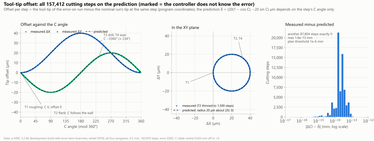
Marked run: the tool-tip offset on every cutting step (its CL minus the nominal run's, in program coordinates). (a) ΔX (blue) and ΔY (aqua) against the C angle, taken as 0–360°. T1 sits at C 0 with an offset of 0, T3 and T4 form one point at 234°, and T2 runs along the dashed black prediction. (b) In the XY plane, the measured points lie on a circle of radius 20 µm about (20, 0); T2 is thinned to 1,500 steps for display. (c) Measured minus predicted, on a log axis: at most 1.6 × 10⁻¹³ mm, against the plan's threshold of 10⁻⁶ mm. The axes of signed values are symmetric, ±45 µm. A HiNC 3.2.46 development build with error-term branches, 0.5 mm.
The first 141 steps touch nothing and do not follow the formula. Step 0 is
T1 M06on line 6 of the first program, with every machine coordinate at 0. Steps 1–140 are the firstG00, on line 10, interpolated outward from there (G43.4is active from line 9). The start is a fixed machine position, and the typed G54 cannot move it. So on these steps the tip is up to 0.020 mm off the formula. The plan's criterion only ever looks at cutting steps.The trimmed runs at 1 mm and the full runs at 0.5 mm have the same tip and machine coordinates at every step. The two nominal runs agree in tip and machine coordinates on all 183,870 steps, and the trimmed marked run meets the prediction to the same 1.58 × 10⁻¹³ mm. Only contact changes with the grid. (
IsTouchedrecords whether the step touches the voxel stock.)- The 1 mm nominal run has 315 fewer cutting steps than the 0.5 mm one, each of them a 1 that became a 0.
- The trimmed marked and nominal runs differ on 5 steps (in T2 and T4).
- The four 0.5 mm runs agree at every step.
So the per-step formula is already proved at 1 mm. The part and the pictures need 0.5 mm.
The part: window walls, spokes and bolt holes
How it was measured: the marked run's exported cut has 6,192,799 vertices. Each one was given its signed distance to the nominal cut (positive = material left, blue in the geometry difference; negative = cut too deep, red).
- The window walls are the vertices that lie within 0.1 mm horizontally of the 7° drafted design faces and at least 0.75 mm from the front and back edges. There are 297,616 of them.
- The hole walls have 25,800 vertices and the seats 12,077.
- Each wall vertex's prediction is cos 7°·d·(cos φ − 1), where φ is the direction (azimuth) of its wall's normal pointing into the window.
- T2's C is that azimuth. In the per-step series, C and the azimuth of the reversed tool axis agree to within 1.4 × 10⁻¹²°. The designer agent also checked on the cutter locations that this azimuth is the wall's normal.
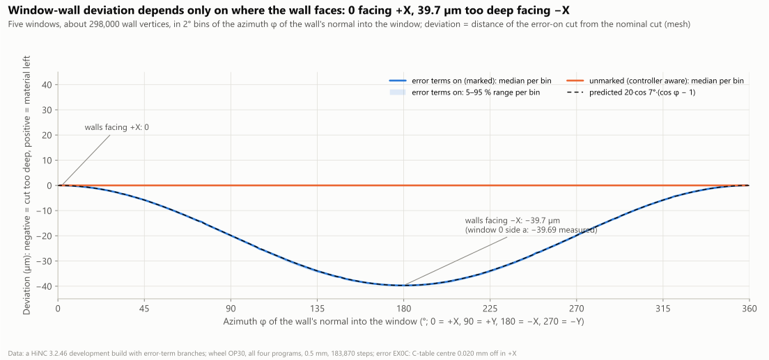
About 298,000 window-wall vertices of the five windows, grouped in 2° bins by φ, the azimuth of the wall's normal into the window (0 = +X, 90 = +Y, 180 = −X, 270 = −Y). Blue is the marked run's median and pale blue its 5–95 % range. Dashed black is the prediction, 20·cos 7°·(cos φ − 1) µm. Orange is the unmarked run, at 0 throughout. The vertical axis is symmetric, ±45 µm; negative = cut too deep. 0.5 mm, a HiNC 3.2.46 development build with error-term branches.
- Only one flat window wall faces −X: window 0, side a, the side of spoke 0 that faces window 0. Its normal points at 177.66°. The median is −39.686 µm over 8,398 vertices, against −39.685 predicted. Taking every window-wall vertex that faces within ±5° of −X, 13,575 of them, the median is −39.686 µm as well.
- The ten flat window walls: the median of measured minus predicted is within 0.02 µm, and 99.999 % of their vertices lie within ±1 µm of the prediction.
- The corner fillets and the inner and outer arcs, 30 pieces in all: the median of measured minus predicted lies between −0.22 and +0.04 µm. The concave corners lean negative and the convex inner arcs positive. This comes from measuring one faceted mesh against another (see Honest limits).
- All 297,616 window-wall vertices: 99.42 % lie within ±1 µm of the prediction.
- The unmarked run: every wall reads 0, below 10⁻⁶ µm.
The ten flat window walls (the two sides of each window, µm)
Side a is spoke j's side facing window j, and side b is spoke j+1's side facing it. φ is the azimuth of the wall's normal pointing into the window.
| Wall | Spoke | φ | Vertices | Measured (median) | Predicted | Measured minus predicted (median) |
|---|---|---|---|---|---|---|
| Window 0, side a | 0 | 177.66° | 8,398 | −39.686 | −39.685 | −0.0003 |
| Window 0, side b | 1 | 74.34° | 9,756 | −14.497 | −14.494 | −0.003 |
| Window 1, side a | 1 | 249.66° | 10,143 | −26.757 | −26.752 | −0.006 |
| Window 1, side b | 2 | 146.34° | 10,868 | −36.389 | −36.374 | −0.015 |
| Window 2, side a | 2 | 321.66° | 10,996 | −4.285 | −4.282 | −0.004 |
| Window 2, side b | 3 | 218.34° | 10,995 | −35.433 | −35.420 | −0.013 |
| Window 3, side a | 3 | 33.66° | 10,870 | −3.331 | −3.328 | −0.003 |
| Window 3, side b | 4 | 290.34° | 10,124 | −12.956 | −12.950 | −0.006 |
| Window 4, side a | 4 | 105.66° | 9,760 | −25.213 | −25.208 | −0.004 |
| Window 4, side b | 0 | 2.34° | 8,352 | −0.017 | −0.017 | −0.0004 |
Spoke width. A spoke's width change is the sum of its two sides' deviations along their normals, measured square to the 7° drafted walls. The horizontal width change is that sum divided by cos 7°.
| Spoke (centre direction) | Its two sides | Measured | Predicted | Difference | Horizontal width |
|---|---|---|---|---|---|
| 0 (90°) | window 0 a −39.686, window 4 b −0.017 | −39.703 µm | −39.702 µm | −0.001 | −40.001 µm |
| 1 (162°) | window 1 a −26.757, window 0 b −14.497 | −41.254 µm | −41.245 µm | −0.009 | −41.564 µm |
| 2 (234°) | window 2 a −4.285, window 1 b −36.389 | −40.674 µm | −40.656 µm | −0.019 | −40.980 µm |
| 3 (306°) | window 3 a −3.331, window 2 b −35.433 | −38.764 µm | −38.748 µm | −0.016 | −39.055 µm |
| 4 (18°) | window 4 a −25.213, window 3 b −12.956 | −38.168 µm | −38.159 µm | −0.010 | −38.455 µm |
- The five spokes are 38.17 to 41.25 µm thinner, 39.7 µm on average, which equals 2d·cos 7°:
- The “every side cut d deeper” term of δ takes d·cos 7° off each side.
- A spoke's two sides are not parallel, so the “whole window moved by d” term does not quite cancel. That is why the spokes differ by about ±1.6 µm.
- Almost all of spoke 0's 39.70 µm comes off its window-0 side (−39.686 µm). Its window-4 side loses only 0.017 µm.
- In the unmarked run, every spoke's change is 0, below 10⁻⁸ µm.
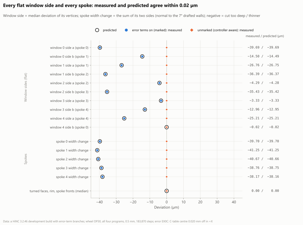
The median deviation of the ten flat window walls and the width change of the five spokes. Blue dots are measured, black rings predicted and orange dots the unmarked run; the right-hand column gives the values. Measured and predicted agree within 0.02 µm. The horizontal axis is symmetric, ±45 µm; negative = cut too deep, or thinner. 0.5 mm, a HiNC 3.2.46 development build with error-term branches.
How far each window moved as a whole. One model was fitted to all the wall vertices of each window: the window shifted by (tx, ty), with every side cut e deeper. All five windows moved 20.02 to 20.04 µm in +X, and within ±0.01 µm in Y. Every side was cut 20.03 µm deeper, measured horizontally. The prediction is (+20, 0) µm and 20 µm.
The five windows' fit (µm)
| Window | Shift X | Shift Y | Every side deeper (horizontal) | Fit rms | Vertices |
|---|---|---|---|---|---|
| 0 | +20.040 | +0.009 | 20.030 | 0.23 | 59,258 |
| 1 | +20.023 | −0.001 | 20.029 | 0.24 | 59,836 |
| 2 | +20.040 | +0.000 | 20.030 | 0.23 | 59,445 |
| 3 | +20.026 | +0.007 | 20.029 | 0.19 | 59,819 |
| 4 | +20.034 | −0.010 | 20.026 | 0.21 | 59,258 |
Bolt holes and seats.
- On every T3 and T4 cutting step, the tip is off by (31.756, 16.180, 0) µm.
- On the mesh, the deviation around each hole wall and seat is fitted with a·cos ψ + b·sin ψ + c, where ψ is the angle around the design hole axis. The dipole (a, b) is the shift of the centre, and c is the change in diameter.
- The mean shift of the five holes is the shift of the bolt circle. It is (31.761, 16.153) µm: 35.63 µm towards 26.96°. The prediction is (31.756, 16.180) µm: 35.64 µm towards 27.0°. Each hole moved 35.57 to 35.69 µm, towards 26.86 to 27.03°.
- The seats moved 35.64 µm towards 27.00°, and they stay concentric with the holes to within 0.03 µm. The cone's dipole along its normal is 30.86 to 30.87 µm, against 30.87 predicted.
- The pitch changes by −0.03 to +0.14 µm. The hole walls' mean deviation is −0.31 to −0.40 µm, which comes from measuring one mesh against another (see Honest limits).
- In the unmarked run, every hole's shift is within 10⁻⁷ µm.
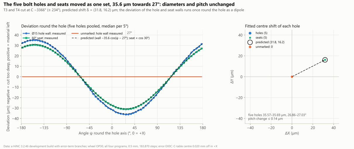
(a) The deviation around the five Ø15 hole walls and 60° seats, with the five holes pooled and the median taken per 5°. It forms a dipole: 35.6 µm too deep on the side towards 27° (30.9 µm on the seat) and material left on the opposite side. (b) Each hole's and seat's fitted centre shift: the five holes 35.57–35.69 µm at 26.86–27.03°, against 35.64 µm at 27° predicted; the unmarked run at 0. The axes are symmetric, ±45 µm. 0.5 mm, a HiNC 3.2.46 development build with error-term branches.
Each hole and seat, fitted (µm)
| Feature | Vertices | Centre shift | Towards | Mean deviation (diameter) | Fit rms |
|---|---|---|---|---|---|
| Hole 0 | 5,160 | 35.568 | 27.03° | −0.40 | 0.54 |
| Hole 1 | 5,160 | 35.640 | 26.96° | −0.33 | 0.50 |
| Hole 2 | 5,160 | 35.635 | 26.86° | −0.36 | 0.58 |
| Hole 3 | 5,160 | 35.625 | 27.00° | −0.35 | 0.45 |
| Hole 4 | 5,160 | 35.695 | 26.94° | −0.31 | 0.48 |
| Mean of the five holes (the bolt circle) | 35.633 | 26.96° | |||
| Seats 0–4 | 2,413–2,419 | 35.637–35.642 | 27.00–27.01° | −0.17 to −0.18 | 0.30–0.33 |
| Predicted | 35.640 | 27.0° | 0 |
The pitch change for holes 0 to 4 is −0.019, +0.054, +0.004, −0.029 and +0.140 µm. The seats' dipole along the normal is 30.863–30.867 µm (predicted 30.865).
The whole cut and the turned faces.
- 94.29 % of the marked cut's vertices lie within 1 µm of the nominal. Only the window walls (0 to −39.7 µm) and the holes and seats (±35.6 µm) move away from 0. The 1st percentile is −36.18 µm and the 99th 4.75 × 10⁻¹⁰ mm.
- 2,899 vertices lie more than 0.05 mm away. 2,856 of them sit on the turned faces of the rim, the same vertices with the same values as in the unmarked run. The other 43 sit on the sharp edges of the shifted holes and seats and read +0.050 to +0.061 mm. Neither group is the error (dilemma 4).
- The turned faces are the hub face, the spoke fronts, the back, the centre bore and the rim, counted more than 2 mm from a window wall and more than 13.5 mm from a hole. 99.9117 % of their vertices lie within the floor, as in the unmarked run. The 5,653,587 vertices that have a counterpart lie at the same distances as in the unmarked run, a difference of 0.
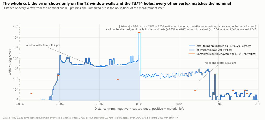
The distance of every vertex of the marked and unmarked cuts from the nominal cut, in 0.5 µm bins with log counts. In the marked run, only the window walls (0 to −39.7 µm) and the holes and seats (±35.6 µm) move away from 0. Of the 2,899 vertices more than 0.05 mm away, 2,856 are the measuring artefact on the rim's turned faces (the same vertices with the same values in the unmarked run), and 43 sit on the sharp edges of the holes and seats. The horizontal axis is symmetric, ±0.06 mm. A HiNC 3.2.46 development build with error-term branches.
The controller that knows the error
This run clears EX0C's mark but leaves the switch on, and it types in the same G54 X 0.020 as the marked
run. The machine is still the one whose C table is 20 µm off, but now the controller's model contains
the offset. That is a controller with calibrated kinematics. Under G43.4, the controller takes the C
table's real centre into account and makes up for it with X and Y.
- Tool tip: within 4.92 × 10⁻¹² mm of the nominal on all 157,412 cutting steps, and the tool axis within 4.5 × 10⁻¹⁶.
- Part: 99.944 % of the vertices lie within 1 µm of the nominal cut. The 2,856 vertices more than 0.05 mm away are all the rim's measuring artefact (dilemma 4). The window walls, spokes and holes all read below 10⁻⁶ µm. The geometry-difference pictures from the three cameras equal the control run's pixel for pixel.
- Machine coordinates: B and C are the same as in the nominal and marked runs, bit for bit. The differences in X and Y fall into three groups, each matching its own formula:
| Comparison | Formula and meaning | Measured | Residual |
|---|---|---|---|
| Unmarked minus nominal | (d, 0, 0): program zero lands on the real C axis, so the whole nominal motion is shifted 20 µm in +X | ΔX = 20.000 µm, ΔY and ΔZ 0, on all 157,412 cutting steps | ΔX differs from 20 µm by at most 4.7 × 10⁻¹² mm; ΔY at most 4.7 × 10⁻¹² mm, ΔZ at most 1.9 × 10⁻¹² mm |
| Marked minus nominal | RZ(−C)·(d, 0): the typed G54 X 0.020 turning with the table; the controller cannot see EX0C | 20 µm long on every cutting step (the 141 starting steps, interpolated from machine zero, excepted) | at most 1.28 × 10⁻¹³ mm (cutting steps) |
| Unmarked minus marked (both with X 0.020 typed) | (d(1 − cos C), d·sin C): what calibration changes in the X and Y positions | 0 to 40 µm long | at most 4.8 × 10⁻¹² mm per axis (all 183,870 steps, from the two runs' per-step series subtracted directly) |
The plan predicted “unmarked: machine X and Y move (d(1 − cos C), d·sin C) further, at most 40 µm”, compared with the nominal run. What was measured is different. That formula describes unmarked minus marked. Compared with the nominal run, every cutting step's position is exactly 20 µm further in +X: the whole motion is shifted, and each step travels the same distance as before (dilemma 2).
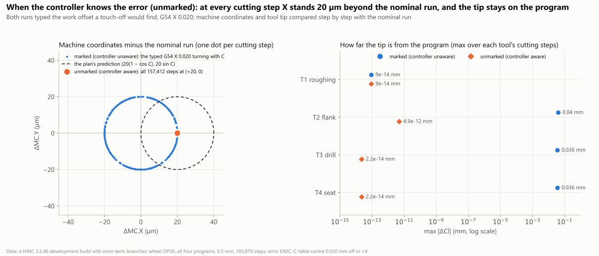
(a) In the unmarked run (the controller knows the error, orange), the machine coordinates of all 157,412 cutting steps lie (+20, 0) µm from the nominal run's. In the marked run (the controller does not know, blue), the only difference is the typed G54 X 0.020 turning with C. Dashed black is the plan's prediction, (20(1 − cos C), 20·sin C) µm. (b) Each tool's largest tip offset from the program on its cutting steps, on a log axis: marked, T2 0.040 mm and T3 and T4 0.036 mm; unmarked, within 4.92 × 10⁻¹² mm. A HiNC 3.2.46 development build with error-term branches.
The geometry difference of the whole wheel in an oblique view (from above −X and −Y). The picture alternates in place between two runs on the same machine with EX0C: the controller unaware of the error (marked) and aware of it (unmarked). With the controller aware, the wheel comes back to the nominal cut, and the picture equals the control run's pixel for pixel. Colour scale ±0.04 mm (red = cut too deep, blue = material left, green = 0, both signs weighted alike); 0.5 mm; a HiNC 3.2.46 development build with error-term branches. The same alternation was also made for the hub close-up and the top view. Because the unmarked frame equals the control frame, those look exactly like the on/off alternations in the next section, apart from their labels.
The control run and the comparison pictures
The control run (switch off, with the geometry difference) is the nominal run played again. Its tip,
machine coordinates and contact are the same on all 183,870 steps, bit for bit. Its Diff--Stats
differ from the unmarked run's only in the unmeasured wires, 3,183 against 3,177. Its
geometry-difference pictures from the three cameras equal the unmarked run's pixel for pixel.
Each of the three pictures below alternates, in place and at one camera, between the error terms on (marked) and off (control).
- The pictures come from putting each run's recorded stock back on the canvas with its geometry difference. Nothing was played again.
- The canvas shows no interface text, so the English and Chinese canvas captures are identical pixel for pixel. Only the labels follow the language.
- The cameras are HiNC's default top and isometric views, zoomed with the mouse wheel.
- The oblique view of the whole wheel is this case's comparison picture.
The geometry difference of the whole wheel in an oblique view (from above −X and −Y), alternating in place between error terms on (marked, G54 X 0.020 typed) and off (control). With the error terms on, the walls facing −X are red (down to −39.7 µm) and the other walls in view yellow to red, by the way they face; the walls facing +X, which stay green, are turned away from this camera. Each of the five seats is red on one side and blue on the other. With the error terms off, everything is green. Colour scale ±0.04 mm (red = cut too deep, blue = material left, green = 0, both signs weighted alike); 0.5 mm; a HiNC 3.2.46 development build with error-term branches.
An oblique close-up of the hub and spoke 0, alternating in place between error terms on (marked) and off (control). With the error terms on, the side of spoke 0 that faces window 0, at the upper left, is red (−39.7 µm). Each of the five seats is red on the side towards 27° and blue on the opposite side. With the error terms off, everything is green. Scale, grid and build as above.
The whole wheel from the top (+Z), alternating in place between error terms on (marked) and off (control). With the error terms on, each of the five bolt holes is red on one side and blue on the other, because the whole set moved towards 27°. Seen from the top, the 7° drafted walls are only narrow bands. With the error terms off, everything is green. Scale, grid and build as above.
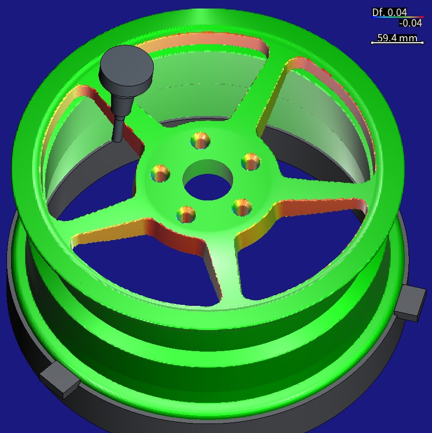
The same scene from further away: the marked run's stock with its geometry difference, after the parking program. T2, the Ø12 mm end mill in its 80 mm shrink-fit holder, stands tilted 7° in window 0, next to the red side of spoke 0 that faces it. Scale, grid and build as above.
Diff--Stats of the four runs with a geometry difference
| Run | Reported leaves | Surface leaves before comparison | Expanded on demand | New nodes | NaN leaves | Measured wires | Unmeasured wires | Target triangles |
|---|---|---|---|---|---|---|---|---|
| Marked | 6,952,184 | 5,460,057 | 727,427 | 2,219,554 | 61 | 27,702,729 | 7,735 | 10,923,368 |
| Control | 6,952,400 | 5,461,611 | 727,461 | 2,218,250 | 22 | 27,706,720 | 3,183 | 10,923,368 |
| Unmarked | 6,952,400 | 5,461,611 | 727,461 | 2,218,250 | 22 | 27,706,720 | 3,177 | 10,923,368 |
| Marked, trimmed (1 mm) | 6,812,493 | 5,196,740 | 764,163 | 2,379,916 | 57 | 27,148,269 | 6,412 | 10,397,158 |
The nominal runs make no geometry difference. The trimmed marked run is compared with the cut of the 1 mm nominal run, which is why its target triangle count is different.
What the runs cost
All runs used private instances of a HiNC 3.2.46 development build with error-term branches, on the shared 32-thread server:
| Play | Grid | Steps | Wall time | Peak memory (VmHWM) |
|---|---|---|---|---|
| Nominal, trimmed | 1 mm | 183,870 | 260.2 s | 9.46 GiB |
| Marked, trimmed | 1 mm | 183,870 | 280.3 s | 19.74 GiB (the second play on the same instance, so it includes the trimmed nominal run) |
| Nominal | 0.5 mm | 183,870 | 330.3 s | 10.65 GiB |
| Control | 0.5 mm | 183,870 | 345.3 s | 15.38 GiB |
| Marked | 0.5 mm | 183,870 | 350.3 s | 17.69 GiB |
| Unmarked | 0.5 mm | 183,870 | 350.4 s | 17.80 GiB |
- Peak memory. VmHWM is the process's high-water mark of resident memory. Each full run started on a restarted instance, so its VmHWM is that run's own peak, including the geometry difference, the export and the stock record. The two trimmed runs ran one after the other on one instance, so the trimmed marked run's figure is the peak of both and cannot be compared with the full runs. GiB = bytes ÷ 2³⁰.
- What the geometry difference and the stock record cost. Three runs compare and record their
stock. Their peaks lie 4.73 GiB (control), 7.04 GiB (marked) and 7.15 GiB (unmarked) above the
nominal run's. The comparison's target is the nominal cut, 10.92 million triangles. Not all of that
extra memory is the comparison itself:
- The nominal run exports its cut but records no stock.
- The control run records its stock but exports nothing.
- The marked and unmarked runs do both.
- The marked and control runs make the same comparison, and still differ by 2.31 GiB.
- Wall time runs from the start of the play to the first poll that read
Finished, so it includes the export, the comparison and the stock record. The status was polled every 5 s, so a wall time can be up to 5 s late. - In all, the six plays took 1,916.8 s, about 32 minutes. The four full runs took 1,376.3 s, about 23 minutes. The times on 2026-10-06: build 20:24:10–20:24:14, trimmed runs 20:24:14–20:33:35, full runs 20:35:15–20:59:29.
- The server was not used by this case alone. While the trimmed runs played, another instance was playing another agent's full run at 0.25 mm almost the whole time. The last 44 s or so of the control run and the first 2.3 minutes or so of the marked run overlapped that study's replay for its holder picture. Those wall times include that load. The nominal and unmarked runs had no such play beside them. VmHWM is each instance's own peak, so it is not affected.
What it means
For a machining engineer.
- A C-table centre only 20 µm off makes each spoke of a five-axis flank-milled wheel about 40 µm thinner. That looks exactly like a cutter radius 20 µm too large. So thin spokes do not always mean the tool or its offset is wrong; the C table's centre can be the cause.
- A touch-off only takes out the offset at the pose where it is made, here C 0. The roughing cut at C 0 does not change at all.
- Three-axis work parked at a C other than the touch-off angle still carries the error into the part. Here that is the drilling and the seats: the five holes moved 36 µm as a set, and the bolt circle is no longer concentric with the centre bore. Either bring vertical work back to the C used at the touch-off, or calibrate the kinematics.
- A controller with calibrated kinematics takes the whole error out. The only difference is the X position at every cutting step, 20 µm further in +X than in the nominal run: the whole motion shifts, and each step travels the same distance as before.
- In HiNC, a constant error measured on a machine can go into that machine's model. Its shape and size on your own part then show before the part is cut.
For a teacher or a student.
- How the location error of a rotary axis becomes the tool-tip offset δ = (I − R(C))·d, and why δ depends only on C.
- δ splits into “everything shifted by d” plus “every side cut d deeper along its normal”. So it looks both like a window that moved and like a wrong cutter radius.
- A surface keeps only the part of the offset along its normal. The wall facing +X does not move at all, and on a drafted face the deviation is multiplied again by cos 7°.
- Marking and not marking correspond to uncalibrated and calibrated kinematics.
- A real machine's touch-off differs from HiNC's P0, which measures on the nominal chain.
- Machine coordinates should be compared with the run that has the same work offset.
For someone weighing the approach.
- Cost. The build and six plays took about 32 minutes of server time. A full run peaked at 17.80 GiB at most. The three runs that compare and record their stock peaked 4.73 to 7.15 GiB above the nominal run, though not all of that is the comparison (see above).
- Predictions. They were written before the first play:
- The tip formula holds on every cutting step to within 1.58 × 10⁻¹³ mm.
- The flat walls and the spokes match to within 0.02 µm.
- The bolt circle's shift matches to within 0.008 µm in length and 0.04° in direction; the predicted and measured centre vectors lie 0.03 µm apart.
- Misses. Where the work missed, the page says what was measured: which run to compare the unmarked machine coordinates with, a control run with no cut, criterion 6d failing vertex by vertex as written, and the ±0.6 mm measuring artefact.
Honest limits
- One error only. This case has only EX0C. A real C table has other errors at the same time: a location error in Y, a tilt of the C axis about X and about Y, and a radial run-out and wobble that vary with the angle. An error term holds only constant errors. It cannot express errors that vary with position (positioning, straightness, volumetric error tables), backlash, servo mismatch or thermal growth (Machine Geometric Error).
- The size and the sign are chosen. 20 µm is a typical value; this generic machine was never measured. With the sign −X, every deviation would turn over: the wall facing −X would keep 39.7 µm of material, each spoke would be about 40 µm thicker, and the holes would move towards 207°.
- The touch-off is typed in, and its angle is assumed. HiNC's P0 measures on the nominal chain and does not take the error in the way a real touch-off does. The G54 X 0.020 of the two runs with the error is derived. The touch-off is assumed at B = C = 0; touched off at another C, the whole pattern would turn with it.
- The holes' result belongs to this NC. T3 and T4 run at C −3366°, the angle where T2 ends. That angle was carried along by the program HiNC wrote back from the cutter locations (the designer agent's reading). A post-processor that writes vertical drilling at C 0 would not move the holes.
- Geometry only. Physics was off, so there is no cutting force, deflection or heat. The base case's T2 finishing deflection was never part of the removal geometry, so the deviations measured here come from the error term alone.
- Reading a 0.5 mm mesh.
- Next to sharp edges, the reading is off. 43 vertices on the sharp edges of the shifted holes and seats read +0.050 to +0.061 mm, so the feature fits use only vertices more than 0.75 mm from an edge.
- On curved faces, measuring two faceted meshes against each other leans with the curvature. The concave R12 corner fillets have a residual median of −0.07 µm (−0.22 for the lowest piece), the convex inner arcs +0.01 µm (+0.04 for the highest), and the hole walls a mean of −0.31 to −0.40 µm.
- The 2,856 rim vertices are a measuring artefact (dilemma 4).
- The control run has no cut of its own. Its noise floor is judged on the evidence of dilemma 5.
- The geometry difference's target has 160 fewer triangles than the STL. HiNC reports 10,923,368 target triangles for the nominal cut, while reading the same STL offline gives 10,923,528. The cause was not looked into.
- Gaps in the records.
- The load messages from reopening the error-term project from its file after EX0C was inserted were not kept. The run records do not hold them, and the play log kept only lines with words such as “error”.
- Whether the case's files outside the error-term folder stayed unchanged was not checked.
- Messages below warning level were not kept, because the records hold only warnings and above.
- The wall times include other load and were polled (see “What the runs cost”, above).
What a reader can take to their own case
- Put the error on a branch of its own, directly upstream of the axis it belongs to. Keep the axis' own motion, its values and its role as they were (Where an Error Term Goes).
- Type in the work offset a touch-off would find. HiNC's P0 measures on the nominal chain, while a real touch-off absorbs the shift the error causes at its pose. Derive the offset from the chain, then check it on the work done at the touch-off pose. Here T1, all at C 0, came out within 8.99 × 10⁻¹⁴ mm of the nominal (Program Zero Alignment).
- Predict the tip offset before the first play, in closed form where one exists. A rotary axis' location error gives δ = (I − R(C))·d. It depends on C alone, so every step of every tool can be checked against it.
- Compare two runs step by step only after showing that their steps line up. Here the four runs at 0.5 mm had the same steps, with the same file, line, tool and contact at each one; the two at 1 mm agreed in file, line and tool and differed in contact on 5 steps. Otherwise, compare by time or by machine coordinates, as the manual says.
- Compare machine coordinates with a run that has the same work offset. Only then does “the switch does not change the machine coordinates” hold.
- Make the nominal cut the ideal geometry. Then the geometry difference shows the error, not the toolpath's own marks.
- Measure the noise floor with a run that should change nothing, and check every extreme in the vertex data before naming its cause. Here the ±0.6 mm extremes were identical in a run that cut the nominal part.
- Read where the program parks C for three-axis work. Drilling at a C other than the touch-off angle carries a rotary axis' location error into the part.
- Prove the per-step formula on a coarse grid, and keep the fine grid for the part and the pictures. At 1 mm and at 0.5 mm, the tip and the machine coordinates agreed at every step.
- Budget memory for the geometry difference and the stock record. Here the three runs that made both peaked 4.73 to 7.15 GiB above the nominal run's 10.65 GiB.
Source and licence
- Wheel size numbers: ANKUSI Open Wheel Fitment Dataset: bolt pattern, centre bore and OE wheel
specifications for 7,603 vehicle variants, ANKUSI Wheels engineering team, figshare, version 4,
2026-09-20, https://doi.org/10.6084/m9.figshare.33921994. Licence:
CC BY 4.0. Search terms if the link moves:
ANKUSI Open Wheel Fitment Dataset,figshare 33921994. - Flange height: de.wikipedia, Autofelge, “Form J, entspricht einer Höhe von 17,3 mm”.
- Attribution: “Wheel size numbers from the ANKUSI Open Wheel Fitment Dataset (ANKUSI Wheels engineering team, figshare, doi:10.6084/m9.figshare.33921994, CC BY 4.0). Wheel design by Tech Coordinate's agent.” The data set is provided as is, without warranty.
- What was used and changed:
- Only three numbers were used, and the CSV itself was not kept.
- The wheel design, the stock, the fixture, the machine, the spindle and every toolpath are the agent's, as the wheel's case page tells. The wheel is not any maker's design and names no vehicle.
- The kind of error, its size, its sign and the touch-off are the agent's choices. EX0C is the name ISO 230-1 and ISO 230-7 give this error; the value is not a measurement of any machine.
- No third-party picture is reproduced. The pictures are HiNC captures, and the charts are drawn from HiNC's per-step results and cut meshes.
- Everything on this page is simulated; no wheel was cut.
See Also
- A 17-Inch Forged Aluminium Wheel — how the wheel, its toolpaths and the programs cut here were made and accepted
- A 17-Inch Forged Aluminium Wheel, Optimized — HiNC's feed optimization of the same programs, a separate study
- Building Virtual Machine Tools: Error terms — what a mark changes, the Enable Error Terms switch, and work offsets on a machine with error terms
- Kinematic Topology: Error-Term Branches — the nominal chain the controller solves, and which errors it can see
- Machining Issues Outside the Model: Machine Geometric Error — the machine errors the model leaves out
- Geometry Validation — the geometry difference, its detection radius and its colour scale
- Program Zero Alignment — P0, and typing in a measured work offset
- Showcase — the other cases, and how a case page reads