A 17-Inch Forged Aluminium Wheel: Designed from Three Public Numbers, Programmed by the Agent, Checked by HiNC Before Any Cut
No licence-clean model of a real car wheel could be found: every wheel model on the open web was either non-commercial, uploaded by someone who is not its author, or a figure in a paper. What is public are fitment numbers — rim size, offset, bolt pattern, centre bore.
An AI agent took three of those numbers and one flange height, designed a one-piece forged 6061 five-spoke wheel of its own, wrote both machining set-ups as five-axis cutter locations in a Python script, and through the HiNC web API let HiNC solve the axes of a table-C / swivel-head-B machine, check every move for collisions, compute the cutting load, write the Fanuc program and replay it. The first trial run already showed the roughing tool driving the spindle past its continuous rating where the agent's own toolpath cut full width; the agent changed the toolpath, and the whole wheel then ran within the spindle's rating. Asked to try HiNC's own feed optimization before publishing, the agent ran HiNC's optimizer, which brought the wheel's machining time from 17 min 25 s to 9 min 36 s, 45 % less, with the spindle within its rating at every step. Most of that came from the ceilings the agent had set on each tool's feed per tooth, and the finishing pass, sped up with the rest, shows why a finishing pass is usually left out. This page is the record, including the small problems. It is a machining demonstration of a wheel of this size, not any maker's wheel.
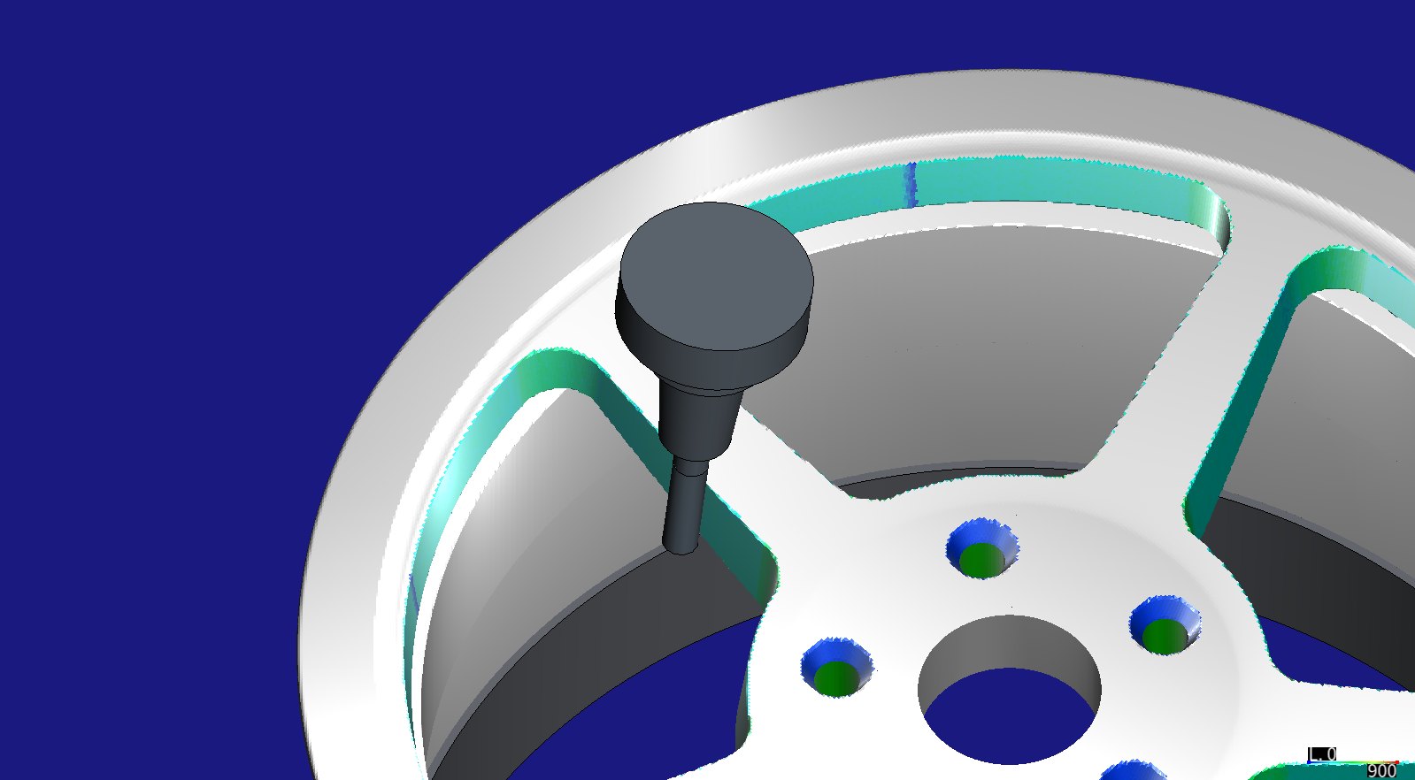
The case
The fitment data set — ANKUSI Open Wheel Fitment Dataset, compiled by the ANKUSI Wheels engineering team on figshare under CC BY 4.0 — lists bolt pattern, centre bore and original-equipment wheel for thousands of vehicle variants. A common row gives:
- Bolt pattern 5 × 114.3 mm.
- Centre bore 60.1 mm.
- Original wheel 17 × 6.5J at ET40: a 17-inch bead-seat diameter, 6.5 inches between the flange faces, the mounting face 40 mm outboard of the rim's centre plane.
The German Wikipedia article on car wheels adds the J flange's height, 17.3 mm. Nothing else is public: no rim contour (the ETRTO and TRA contour standards are paid documents and were not used), no disc, no spokes, no stock, no fixture, no toolpath, no machine. The case names no vehicle.
What the agent built
Each value is marked read (from the public numbers), derived (computed from them) or chosen (the agent's own design or process choice).
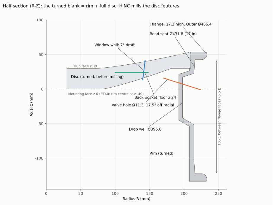
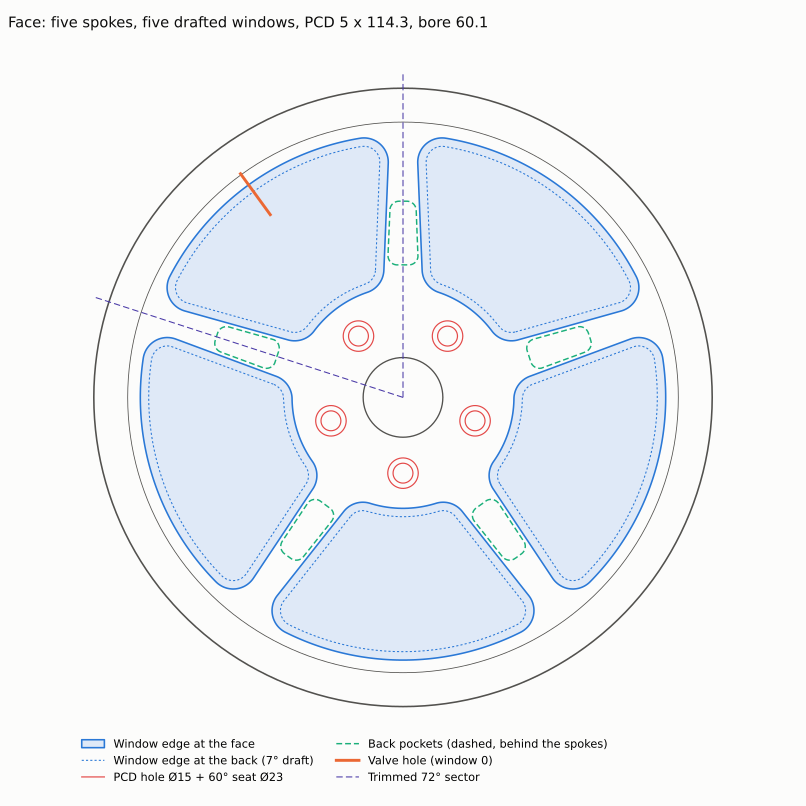
| Item | Value |
|---|---|
| Rim | bead seat Ø431.8, 165.1 mm between the flange faces, rim centre 40 mm inboard of the mounting face — read; J flange 17.3 mm high, outer diameter 466.4 mm — read / derived; 11 mm flange with an R8 curl, 20 mm bead seats with a 5° taper and no humps, a 16.25 mm drop well (Ø395.8) on the outboard side whose outboard wall is 17.5° off the radial plane and inboard wall 30°, walls 6.5 mm under the seats and 5.5 mm in the well — chosen |
| Disc | hub face 30 mm outboard of the mounting face, flat out to R75; a concave spoke face rising to 51.5 mm at R200; the back rising from the mounting face at R82 to 30 mm at R182, with a turned relief behind the lip ring — chosen |
| Spokes and windows | five spokes, their half-width tapering from 21 mm at R90 to 16.5 mm at R200; five closed windows whose walls have a 7° draft (wider at the face) and R12 corners, both measured in the mounting-face plane — chosen. A constant draft makes every piece of wall a plane or a cone, which a cylindrical cutter can flank exactly. |
| Holes | PCD 114.3 — read; Ø15 holes for M12 × 1.5 studs with 60° cone seats Ø23 at the hub face, in line with the windows — chosen; the 11.3 mm valve hole through the well, its axis 17.5° off the inward radial towards the face — chosen |
| Back pockets | one behind each spoke, flat floor 24 mm outboard of the mounting face, R100–148, 6 mm walls, R7 corners — chosen |
| Stock | the turned wheel: rim and full disc, 14.5 kg; OP30 removes 4.9 kg and the finished wheel is 9.4 kg — derived from the design |
| Set-ups | OP30 face up on the inboard lip (windows, drafted walls, PCD holes, seats); OP40 turned over onto the outboard lip (back pockets, valve hole) — chosen. Two projects: the agent turned the wheel over in its own geometry and toolpaths, so each project's workpiece placement is a plain translation. |
| Program zero | on the wheel's axis in the mounting face — chosen |
| Machine | a generic table-C / swivel-head-B five-axis machine built from plain solids by an earlier case's script, Ø520 table — chosen |
| Fixture | a Ø476 support ring under the lip face and three jaws on the lip's outer diameter, placed clear of the valve in both set-ups — chosen |
| Controller | Fanuc dialect; travel X ±900, Y ±600, Z −1000 to 400 mm, B ±110° — chosen |
| Material | forged 6061-T6 — read (the case's premise); HiNC's Al6061T6 library material and cutting parameters |
| Spindle | a synthesized 15,000 rpm motor spindle, 22 kW continuous and 30 kW short-term, 117 / 159 N·m below 1,800 rpm — chosen; not a maker's data sheet |
| Tools and holders | T1 Ø20 end mill, 60 mm stick-out; T2 Ø12 end mill, 40 mm flute, 55 mm stick-out; T3 Ø15 drill; T4 Ø25 60° countersink; T6 Ø12 end mill in a 130 mm slim shrink-fit holder; T5 Ø11.3 drill — all generic, in holders of real proportions — chosen |
| Toolpaths | NX CLSF written by the agent's script: T1 window roughing in six levels with helical entries; T2 five-axis flank of the drafted walls (B 7° throughout, C following the wall), a 0.4 mm semi pass then the final pass; T3 drilling; T4 seats; T6 back pockets in 4 mm levels; T5 valve drilled from the tire side at B 72.5° — chosen |
| Mission | per set-up: the toolpath played on the machine with the Fanuc G43.4 write-back on; the written program replayed on the same machine — chosen |
The work in order, from the lathe to the second set-up:
| Operation | Work holding | What is cut |
|---|---|---|
| Turning, outside HiNC | lathe | the rim inside and out, both faces of the disc, the centre bore |
| OP30 | face up, on the inboard lip | T1 roughs the five windows → T2 flanks their 7° drafted walls in five axes → T3 drills the five stud holes → T4 cuts their 60° seats |
| OP40 | turned over, face down, on the outboard lip | T6 reaches down inside the barrel to cut the five back pockets → T5 drills the valve hole from the tire side at B 72.5° |
The six tools as the agent's script defines them. The clearances are its own check at every cutter location against the turned blank, which contains every in-process state; the last column is the ceiling each tool was given when HiNC's feed optimization was tried (below).
| Tool | Cutter | Stick-out + holder | What it cuts | Spindle and feed | Least clearance to the blank, holder / shank | Optimizer's ceiling, feed per tooth |
|---|---|---|---|---|---|---|
| T1 | Ø20 end mill, 3 flutes, 45 mm flute | 60 + 85 mm shrink-fit | OP30 window roughing: 6 levels along the offset tree, a helical entry for each branch, 0.5 mm left on the walls | 12,000 rpm, 4,320 mm/min; slowed in proportion where it cuts wider than 8 mm, down to 2,600 mm/min | 21.1 / 7.5 mm | 0.18 mm |
| T2 | Ø12 end mill, 3 flutes, 40 mm flute | 55 + 80 mm shrink-fit | OP30 five-axis flank of the window walls: a 0.4 mm semi-finishing pass, then the finishing pass, the tool's end 2.5 mm below the back of the disc | 15,000 rpm, 3,600 mm/min | 21.6 / 7.6 mm | 0.10 mm |
| T3 | Ø15 drill, 140° point | 60 + 85 mm | OP30 stud holes, one chip-breaking retract | 6,000 rpm, 1,500 mm/min | 25.8 / 10.8 mm | 0.15 mm |
| T4 | Ø25 60° countersink | 35 + 60 mm collet chuck | OP30 60° seats, Ø23 | 4,000 rpm, 400 mm/min | 15.1 / 1.7 mm | 0.05 mm |
| T6 | Ø12 end mill, 3 flutes, 26 mm flute | 50 + 130 mm slim shrink-fit | OP40 back pockets in 4 mm levels, floor and walls finished to size | 14,000 rpm, 2,520 mm/min | 27.3 / 5.7 mm | 0.10 mm |
| T5 | Ø11.3 drill, 140° point | 45 + 80 mm | OP40 valve hole at B 72.5°, fed back out of the wall after breaking through | 7,000 rpm, 1,400 mm/min | 24.3 / 15.8 mm | 0.14 mm |
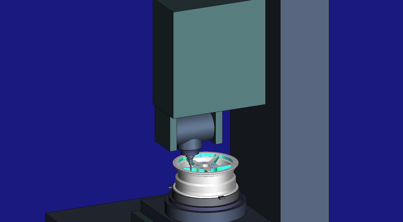
How the agent managed the work
- Pass criteria first. Six criteria were committed before the first play: clean plays; no collision (the engine's messages and the agent's own clearance check at every point); spindle power and torque within the spindle's ratings and tool stress below yield; the machined part within ±0.3 mm of the design on the milled faces with no turned face cut deeper than 0.3 mm; the cycle time (target 20 min); and HiNC's written program agreeing with the toolpath.
- Trimmed first. A 72° sector — one window, its PCD hole, the valve and half of two back pockets — at 1 mm, then 0.5 mm; the whole wheel once at 1 mm to size the memory, and once at 0.25 mm for the acceptance, queued behind other agents' acceptance runs on a shared lock.
- Its own checks where the engine is silent or the agent is the source. The agent's script measured the holder and shank against the turned blank at every cutter location, and the spindle head, fork and trunnion against the wheel, the jaws and the table in the valve pose. A positive control — a holder driven on purpose into the wheel's lip — proved the engine reports holder contact, so its silence in the real runs means something.
- Where the owner stepped in. Shown the finished record, the owner said to publish it and asked first for HiNC's own feed optimization to be tried. The agent wrote down the optimization's settings and four criteria for it before its first optimization run, as it had for the case itself.
- A shared machine. The runs used a private copy of the deployed HiNC on a 32-thread server that also serves live instances and other agents; the acceptance ran with a memory watchdog and a floor of free memory below which it would not start.
The six criteria as committed before the first play:
| # | Criterion |
|---|---|
| 1 | Every play finishes; every program has steps and every tool touches the part; no error in any message sink and no warning in step or ncManip (none accepted in advance) |
| 2 | No Collided(...) message in any play (machine, fixture, holder, shank); in the agent's own check at every cutter location against the turned blank, the holder at least 10 mm and the shank at least 1 mm clear; for the valve drill at B 72.5°, the spindle nose, housing, B drum and fork at least 20 mm from the wheel, the jaws and the table |
| 3 | At every step MaxSpindlePowerRatio ≤ 1 and MaxSpindleTorqueRatio ≤ 1 (written “against the 22 kW continuous curve”, see dilemma 7), and YieldingStressRatio < 1 for every tool; the force peaks where T1 enters the window corners recorded, with no threshold |
| 4 | On the whole wheel at 0.25 mm, the part HiNC exports after OP30, and after OP40, within ±0.3 mm of the design (the agent's 0.2 mm tolerance plus half a cell) at 99 % or more of the points sampled on the milled faces, and no point of the turned faces cut deeper than 0.3 mm |
| 5 | HiNC's simulated time for OP30 + OP40 recorded; the target 20 min or less without tool changes and loading (the agent's estimate of 16.3 min plus 20 %) |
| 6 | The Fanuc program HiNC writes back replays with criteria 1–4 met and the same peak cutting depth per program within 0.05 mm |
The dilemmas
Each is told as its situation, the risk had it been missed, how it was noticed, the resolution, and the evidence that the resolution held.
1. No wheel model to start from
- Situation. Every wheel model found was non-commercial (a research data set under CC BY-NC), uploaded by someone other than its author, or a figure in a paper.
- Risk. A case built on a model of unclear licence cannot be published at all.
- Resolution. The agent designed the wheel itself from three CC BY numbers and one flange height, marked every other number as its own choice, and kept the rim contour its own simplification rather than a paid standard's. The page calls the result a machining demonstration of a wheel of this size and names no vehicle.
2. Open windows or closed ones?
- Situation. On many real wheels the windows run out to the inside of the barrel.
- Risk. Where a drafted window wall meets the turned barrel, the wall would need a draft that changes along it — a twisted surface that a cylindrical cutter cannot flank exactly — and the comparison with the design would show stock or gouges in every corner.
- Resolution. Closed windows with one 7° draft all round and R12 corners: every piece of wall is a plane or a cone, so the tool touches along a whole straight line. The straight spoke sides are cut as 3+2 (B 7° and C fixed); the corners and arcs as simultaneous five-axis (B 7°, C turning). A lip ring 6–9 mm wide stays between the windows and the barrel.
- Evidence. On the whole wheel at 0.25 mm the milled faces lie within −0.178 to +0.031 mm of the design (below).
3. Where can the valve hole be drilled from?
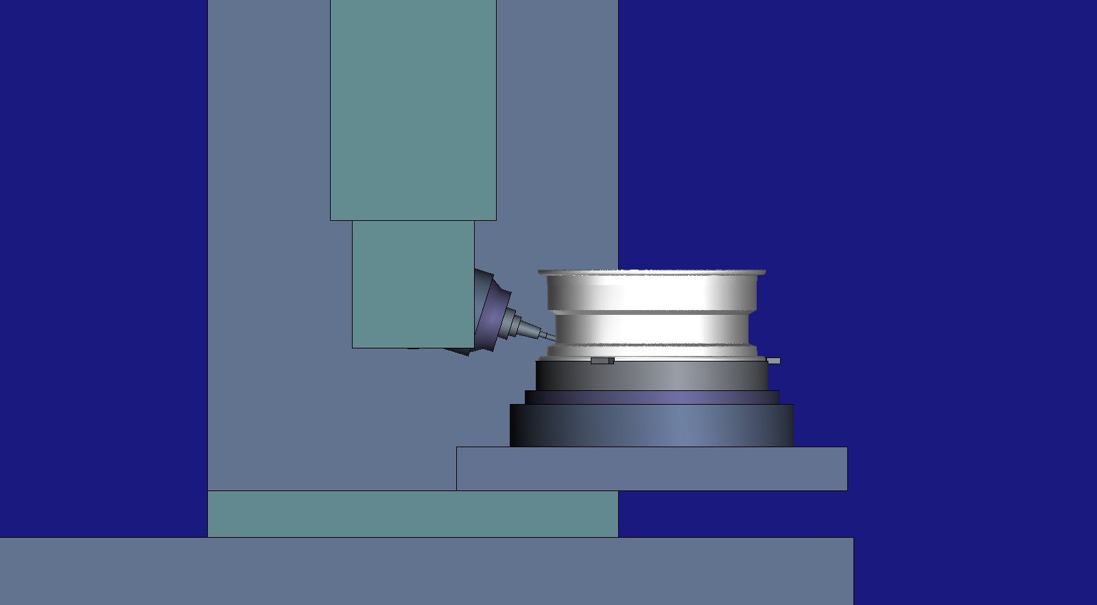
- Situation. A valve hole has to go through a wall roughly square to it for the valve to seal. Seen from the face, the only wall of the rim in reach through a window is the well's cylinder.
- Risk. Drilled from the face through a window, the drill would meet that cylinder at 72°, and the spindle head would have to lie almost flat over the hub.
- Resolution. The hole runs through the well 17.5° off the radial towards the face, so the valve stem points out through the window, and it is drilled from the tire side in the second set-up, with the head tilted to B 72.5° outside the wheel. The agent's script placed the machine's nose, spindle housing, trunnion drum and fork arms around that tool position and measured them against the wheel, the jaws and the table.
- Evidence. The nearest part of the head stays 67 mm from the wheel and 78 mm from the jaws and table; the engine reported no collision in the drilling.
4. A back pocket whose holder would hit the barrel
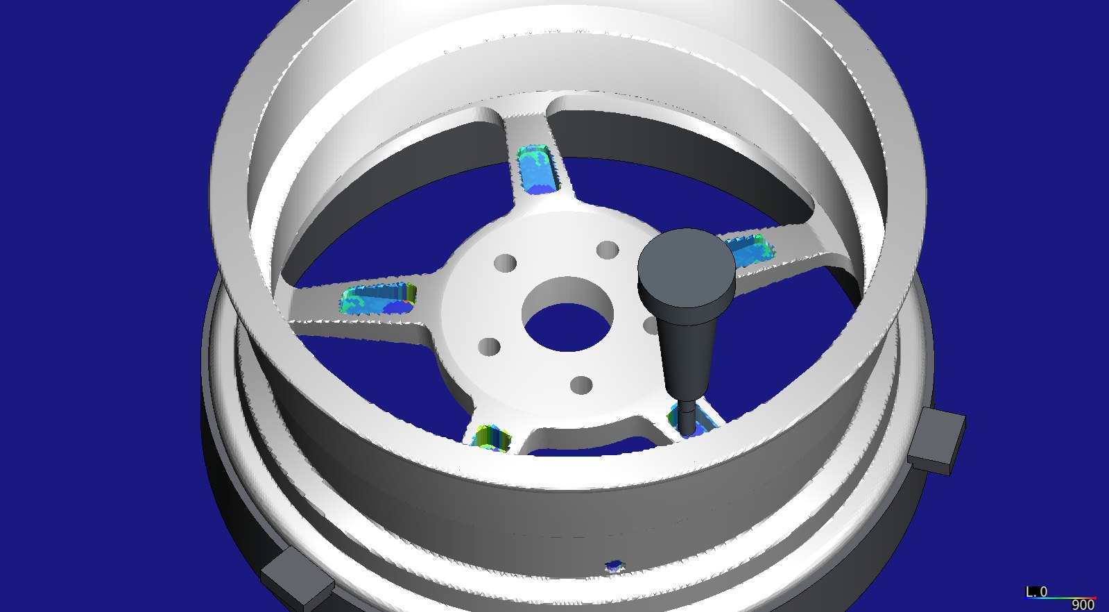
- Situation. The first idea was a pocket floor parallel to the spoke face, 10° from flat, cut with the tool square to it.
- Risk. Tilted outwards, a tool reaching 160 mm into the barrel drifts 28 mm sideways; the agent's clearance check put its holder into the inside of the bead seat.
- Resolution. A flat floor cut with the tool vertical, from a slim 130 mm shrink-fit holder that keeps the spindle nose above the inboard lip.
- Evidence. The holder stays at least 27 mm from the blank at every point; no collision.
5. Turning the wheel over
- Situation. The back pockets and the valve hole need the wheel face down.
- Risk. An earlier case found that a tilted or rotated program zero makes a cutter-location play and a replay of the written program cut in different places, with no message.
- Resolution. Two projects: the agent turned the wheel over in its own geometry and toolpaths, so both projects place the workpiece by plain translation. The second set-up starts from the designed result of the first; HiNC's own result of the first set-up is checked against the same design (criterion 4).
6. The first trial run: the roughing past the spindle's continuous rating
- Situation. On the 72° sector at 1 mm every message was clean, but HiNC's per-step results showed the Ø20 roughing tool at 96 % of the spindle's short-term rating and 130 % of its continuous rating, and 997 of its 22,525 cutting steps above the continuous rating.
- Risk. A program that looks right on screen but runs the spindle past its rating in bursts either trips the drive or wears the spindle and the tool.
- How it was noticed. The per-step results carry each step's program line; the peaks sat on a 26 mm straight link between two pieces of one level that ran through uncut stock — a full-depth slot — and on step-over loops that met a full-width band in a narrow neck (the cutting width of those steps had a median of 19.3 mm on a 20 mm tool).
- Resolution. Two changes to the agent's own toolpath: each level is cut along its offset tree, each branch with its own helical entry, so every link runs inside stock already cleared; and the script tracks the area cleared so far and measures the width each move of 2 mm or less cuts into, slowing a move in proportion when it cuts wider than 8 mm, down to 2,600 mm/min. This is what a CAM system's engagement-based feed does; here HiNC's per-step spindle power told the agent where.
- Evidence. On the sector at 1 mm: 69 % of the short-term and 94 % of the continuous rating, no step over the continuous rating, 8 % more time. On the whole wheel at 0.25 mm: 67 % of the short-term and 91 % of the continuous rating, no step over the continuous rating.
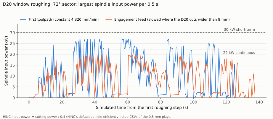
The Ø20 roughing on the 72° sector at 1 mm, before and after the change (the chart above is from the 0.5 mm plays):
| First toolpath | Engagement feed | |
|---|---|---|
Short-term power ratio, MaxSpindlePowerRatio |
0.957 | 0.689 (whole wheel at 0.25 mm: 0.669) |
Continuous power ratio, ContinueSpindlePowerRatio |
1.305 | 0.940 (whole wheel at 0.25 mm: 0.912) |
| Cutting steps over the continuous rating | 997 of 22,525 (4.4 %) | 0 |
| Half-second windows over 22 kW in the chart (0.5 mm) | 57 of 253 | 0 |
| Simulated time of OP30 on the sector (T1 to T4) | 2:26.8 | 2:38.5 (+8 %) |
7. Which spindle curve is the ratio against?
- Situation. The criterion said the power ratio should stay within the 22 kW continuous rating;
HiNC's
MaxSpindlePowerRatiodivides by the short-term curve, and its continuous twin isContinueSpindlePowerRatio. Both use the spindle's input power, the cutting power divided by HiNC's default efficiency of 0.4, which HiNC validated against measured spindle load. - Resolution. The criterion was left as written, the misnamed curve noted next to it, and both ratios reported.
8. A rapid retract flagged as cutting
- Situation. HiNC reported
Play-RapidCut--Detected: the rapid retract out of the valve hole just drilled removed 0.00015 mm³ — a numerical residue, not a real cut. The criteria accepted no warning. - Resolution. Rather than raise the threshold, the drill now feeds back out of the wall before the rapid, as drilling cycles commonly do; the warning is gone.
9. Does the engine check the holder at all?
- Situation. The real runs reported no collision, which means something only if the engine reports a holder driven into the stock.
- Resolution. A positive control: T6 held in the air outside the barrel with its holder driven
into the inboard lip. HiNC reported 658 steps of
Collided(Workpiece,ToolHolder)orCollided(Workpiece,CutterShank); so no collision in the real runs means no collision.
10. A replay that seemed to cut nothing
- Situation. The first check of a replayed Fanuc program found the milled faces 96 % oversize.
- How it was noticed. The measurement, not a message: the replay itself reported the same cutting loads as the toolpath.
- Cause and resolution. The agent's play script added the program entries for the written programs after an older “export the part” entry, so the export ran before the programs. The script now recreates the export entry last on every play; replay and toolpath then measure alike.
11. Checking the checker
- Situation. The agent's comparison script, run against the design itself, reported deviations of ±13 mm.
- Cause. Long thin triangles on the turned surfaces defeated its nearest-triangle search, and a 0.1 mm grid was too coarse to tell turned faces from milled ones.
- Resolution. The mesh is subdivided to 2 mm edges before the search, and a face counts as turned when it lies within 0.02 mm of the turned blank's mesh. Against itself the script then reads within ±0.3 mm at 99.96 % of the points; its noise floor is one point in a sharp corner.
12. Edges that no tool touched
- Situation. At 1 mm and 0.5 mm the worst deviations sat on edges: −0.7 mm on convex edges and +0.6 mm in concave corners, including the edges of the inboard lip that no tool comes near.
- Resolution. That is the mesh width rounding edges and filling corners, not the toolpath; the acceptance ran at the 0.25 mm written into the criteria. At 0.25 mm one point per set-up remains beyond 0.3 mm, −0.3015 and −0.3188 mm, both on edges no tool touches in that set-up (criterion 4 below).
13. The toolpath cannot be optimized as a toolpath
- Situation. HiNC optimizes a program by rewriting its lines; for cutter-location files that path is not connected.
- Resolution. The optimizer ran on the Fanuc program HiNC itself wrote back from the agent's toolpath, which the acceptance had already shown to cut exactly like the toolpath, and the optimized Fanuc program was replayed on the same machine.
14. Optimizing the first toolpath or the fixed one?
- Situation. The agent had already slowed its roughing where it cut full width. Should HiNC's optimizer start from that, or from the first, constant-feed toolpath that overran the spindle?
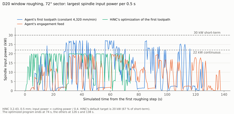
- Resolution. Both, on the 72° sector. The optimizer solves every step's feed afresh, so the two optimized programs came out alike: 74.4 and 74.6 s against 126.1 s for the first toolpath and 137.7 s for the agent's fix, both held at HiNC's default target of 20 kW input with no step over the continuous rating.
Results and benefits
Measured on HiNC 3.2.43 at 0.25 mm unless stated; the criteria are the six written before the first play.
| Measure | Value | Criterion |
|---|---|---|
| Plays | every program of both set-ups played to its end, as the agent's toolpath and again as the Fanuc program HiNC wrote from it: OP30 184,650 / 183,870 steps, OP40 61,217 / 60,021; no error, no warning | 1 ✓ |
| Collisions | none in the four plays (the positive control gave 658 steps); the agent's own check: holders at least 15.1 mm and shanks at least 1.7 mm from the turned blank (both the countersink's), the spindle head 67 mm from the wheel in the valve pose | 2 ✓ |
| Spindle and tools | power 0.669 of the short-term and 0.912 of the continuous rating (T1), no step over the continuous rating; torque 0.282 (T1); tool stress 0.368 of yield (T5) | 3 ✓ |
| Milled faces within ±0.3 mm of the design | 100 %: OP30 24,643 points from −0.178 to +0.002 mm, OP40 29,515 points from −0.115 to +0.031 mm | 4 ✓ |
| Turned faces cut more than 0.3 mm | one point in 275,357 at −0.3015 mm (OP30, where the inboard flange face meets the barrel) and one in 270,485 at −0.3188 mm (OP40, the sharp exit edge of a stud hole in the mounting face); no tool touches either edge in that set-up | 4 ✗ (one point per set-up) |
| Simulated machining time | OP30 13:17.1 + OP40 4:16.5 = 17:33.6 (the written programs 13:13.6 + 4:11.5 = 17:25.1); no tool changes, loading or turn-over | 5 ✓ (20 min) |
| Written program against toolpath | the peaks of cutting depth, force, power ratio and stress equal digit for digit in all six programs; the exported parts evaluate identically | 6 ✓ |
| Run cost on the shared 32-thread server | OP30 1,146 s as toolpath, 1,982 s as program; OP40 225 s and 185 s; peak memory 15.8, 15.7, 11.8 and 12.0 GB, with the part comparison off | — |
Criterion 4 is not met as written, by one point per set-up. Both points sit on sharp edges that no tool touches in that set-up, and deviations of the same kind, a little smaller, appear on other untouched turned faces at symmetric angles: they are the 0.25 mm grid's picture of the turned blank itself, not the toolpath. The criterion stays as it was written, and the verdict with it.
Per tool, the whole wheel as toolpath:
| Tool | Steps | Simulated time | Largest force | Power ratio, short-term / continuous | Torque ratio | Stress ratio | Deepest cut |
|---|---|---|---|---|---|---|---|
| T1 Ø20 roughing | 153,370 | 11:29.1 | 944 N | 0.669 / 0.912 | 0.282 | 0.153 | 8.69 mm |
| T2 Ø12 flank | 29,506 | 1:27.4 | 527 N | 0.262 / 0.358 | 0.132 | 0.240 | 30.13 mm |
| T3 Ø15 drill | 1,108 | 0:10.9 | 504 N | 0.310 / 0.423 | 0.124 | 0.034 | 2.97 mm |
| T4 60° countersink | 666 | 0:09.7 | 119 N | 0.171 / 0.233 | 0.049 | 0.009 | 7.00 mm |
| T6 Ø12 back pockets | 60,940 | 4:14.1 | 764 N | 0.402 / 0.548 | 0.173 | 0.246 | 20.25 mm |
| T5 Ø11.3 valve drill | 277 | 0:02.4 | 503 N | 0.165 / 0.225 | 0.061 | 0.368 | 9.20 mm |
T1's largest force is in its second level; T6's is on the last floor pass, where the floor and wall allowances are cut together; T5, drilling through the well's cylinder at a slant, has the highest stress of the six. T2's “depth” is the length of flute in contact on the drafted wall.
HiNC's feed optimization
This case's NC-optimization page goes further: three optimized versions of all six programs, each replayed on the whole wheel, two of them with the finishing passes left at their programmed feed.
HiNC's default targets: the spindle held to 67 % of its short-term rating (20 kW input) in power and torque, with the mission's yield and target-force limits off (the tool's own yield limit stayed on, as the whole-wheel run below shows); each tool's maximum feed per tooth as the ceiling. The optimized Fanuc programs were replayed on the same machine and measured as the acceptance was, at 0.5 mm. On the 72° sector, T1 only:
| Roughing program | T1 time | Power ratio, short-term / continuous | Steps over continuous | Largest force | Stress ratio |
|---|---|---|---|---|---|
| The first toolpath, constant 4,320 mm/min | 2:06.1 | 0.903 / 1.231 | 789 | 922 N | 0.150 |
| The agent's engagement feed | 2:17.7 | 0.650 / 0.886 | 0 | 919 N | 0.150 |
| HiNC's optimization of the first toolpath | 1:14.4 | 0.669 / 0.913 | 0 | 1,251 N | 0.207 |
| HiNC's optimization of the engagement feed | 1:14.6 | 0.677 / 0.923 | 0 | 1,251 N | 0.207 |
The optimizer holds power and torque, not force: where it sped up cuts that used little power, the largest force rose by a third, to 1,251 N, and the tool stress to 0.207 of yield, still far below it. Both optimized programs came out slightly above the 0.667 target, as HiNC's documentation says a replay can.
On the whole wheel at 0.5 mm, every program of both set-ups: the Fanuc programs as accepted, and HiNC's optimization of them replayed on the same machine.
| Program | Before | After | Change | Cutting steps at the feed ceiling | Power ratio after, short-term / continuous | Stress ratio, before → after | Largest force, before → after |
|---|---|---|---|---|---|---|---|
| T1 Ø20 roughing | 11:25.4 | 6:09.5 | −46 % | 86 % | 0.679 / 0.925 | 0.150 → 0.207 | 919 → 1,253 N |
| T2 Ø12 flank | 1:26.5 | 1:06.7 | −23 % | 99.7 % | 0.375 / 0.512 | 0.251 → 0.333 | 551 → 715 N |
| T3 Ø15 drill | 0:11.2 | 0:12.2 | +9 % | 95 % | 0.362 / 0.493 | 0.033 → 0.039 | 456 → 530 N |
| T4 60° countersink | 0:10.5 | 0:10.0 | −5 % | 100 % | 0.172 / 0.234 | 0.009 → 0.009 | 118 → 59 N |
| T6 Ø12 back pockets | 4:08.3 | 1:54.4 | −54 % | 99.97 % | 0.541 / 0.738 | 0.264 → 0.333 | 820 → 1,013 N |
| T5 Ø11.3 valve drill | 0:03.2 | 0:02.7 | −16 % | 77 % | 0.224 / 0.306 | 0.367 → 0.332 | 498 → 451 N |
| Both set-ups | 17:25.1 | 9:35.5 | −45 % |
The four criteria written for the optimization were met. O1: both replays played every line with no warning and no collision (OP30 114,952 steps, OP40 28,831). O2: the largest power ratio was 0.679 of the short-term and 0.925 of the continuous rating (T1), torque 0.378, stress 0.333 of yield. O3: at 0.5 mm the milled faces lie within ±0.3 mm on 99.98 % of OP30's points (five below, the lowest −0.366 mm, where the 0.5 mm grid rounds edges, dilemma 12) and on 100 % of OP40's. O4: 17 min 25 s became 9 min 36 s.
What set the feed. The optimizer writes, for every step, the feed per tooth each limit would allow. On 86 % of T1's cutting steps, and on nearly every step of the other tools, the ceiling the agent had chosen, each tool's maximum feed per tooth, came first; the spindle's power target held only T1's thickest cuts, 14 % of its steps. The tool's own limit, HiNC's default, also holds the stress to a third of yield (its safety factor of 3 and the mission's are compared and the larger applies, so the mission's “yield off” did not switch it off), which is where T2, T6 and T5 stop at 0.333. The time saved therefore rests on those ceilings as much as on the spindle.
Where the time came from. Of T1's 316 s saved, 241 s came from cutting steps and 75 s from feed moves in air, which the optimizer runs at the 20,000 mm/min it is given for cuts in air. Three places went the other way: the Ø15 drill came out a second slower, because HiNC's relief-angle limit holds its feed per tooth down to 0.033 mm while the point enters and the engaged radius is small; the countersink's moves at 1,200 mm/min that already touched the hole's edge were brought to its 0.05 mm ceiling, 400 mm/min; and the first step of each of the 14 ramps into a new pocket level fell to the 300 mm/min minimum.
The finishing pass. The optimizer took T2's finishing flank from 3,600 mm/min to its ceiling, about 4,500 mm/min, and its largest cutting force from 551 to 715 N; the tool's deflection grows with the force. HiNC's per-step results give that deflection, but its removal geometry, and so the comparison with the design, does not include it. On a finishing pass the wall is the result, so a finishing pass is usually left out of a feed optimization or given a ceiling of its own; here it was optimized like the rest, and the larger deflection is what that costs.
The optimization play of OP30 took 632 s and brought the instance's memory to 26 GB, more than the 0.25 mm acceptance needed, and OP40's took 155 s; the replays took 305 s and 85 s.
For a machining engineer. Before any aluminium was cut, HiNC showed that a two-set-up five-axis program for a wheel clears its holders and the swivel head, gave the time of every program, and pointed at the moves of a roughing that looked clean where the spindle ran past its continuous rating. HiNC's optimizer then took 45 % off the wheel's machining time with the spindle inside its rating at every step; the result rests mostly on the feed ceilings given to each tool, and on the finishing pass it raised the tool's deflection, which the comparison with the design does not see.
For a teacher or a student. One wheel shows why a constant draft lets a cylindrical cutter finish a window exactly, 3+2 and simultaneous five-axis on the same wall, why a valve hole is drilled from the tire side, where contour-parallel roughing hides full-width cuts, what a spindle's short-term and continuous ratings mean, and what a feed optimizer holds constant and what it does not.
For someone weighing the approach. From three public numbers, the agent designed the wheel, wrote its own CAM and its own checks, and brought two five-axis set-ups to an accepted simulation; HiNC's per-step results changed the agent's toolpath once, and HiNC's optimizer then did the feed work a hand-written toolpath does badly. The four acceptance plays ran 59 minutes on the shared server; a 1 mm trimmed run takes half a minute, a 0.5 mm one a minute. The toolpaths are of demonstration quality: chip evacuation, chatter and surface finish were not considered.
Honest limits
- The wheel is the agent's design, from three public numbers and one flange height; its rim contour, disc, spokes and holes are the agent's choices, not a maker's wheel and not a standard's contour. It has not been checked for strength, fatigue, balance or fit on a vehicle.
- Turning, forging and heat-treatment distortion are outside HiNC. The stock is the finished turned wheel, perfectly round and in place.
- The machine, the fixture and the spindle are generic. The spindle's ratings are synthesized; HiNC compares its input power, the cutting power divided by 0.4, with them.
- Cutting loads come from HiNC's library coefficients for 6061-T6 with generic tools of the agent's choosing; no force or power was measured. What the model says is where the load is high relative to the rest of the program and relative to the spindle's curve.
- Not modelled: chatter of the thin lip and spokes, burrs, surface finish, chip evacuation from the deep windows, coolant.
- Tool deflection is not in the comparison with the design. HiNC removes material along the programmed path; the finishing flank's modelled tip deflection would add to the wall's error on a real machine, which criterion 4 does not read.
- The optimization's gain rests on the agent's feed ceilings, typical values for end mills and drills in aluminium, not a tool maker's data for these tools. On a pointed cutter HiNC places the cutting force where the engagement is, 13–16 mm up the cone at the rim of the Ø15 hole for this countersink; replaying the Ø15 drill and the countersink alone on the whole wheel at 0.5 mm, on a HiNC build of 2026-10-01, reads the countersink's largest tip deflection as 0.39 µm (at 34 N) and nothing measurable at its 118 N peak, where the two flutes' forces cancel; the drill reads 0.75 µm axially at its 504 N thrust and no lateral deflection past its entry step.
- The cycle time is HiNC's simulated time of cutting and rapid moves without tool changes, loading or probing.
What a reader can take to their own case
- Write the pass criteria before the first run, and keep them as written: when a criterion turns out to name the wrong quantity or misses by a hair, say so next to it rather than rewriting it.
- Read the per-step results, not only the messages. A clean message list said nothing about the spindle running past its continuous rating; the per-step power with the program line of every step pointed at the exact moves.
- When you are the CAM, check your own linking and engagement. Contour-parallel roughing links and narrow necks are where full-width cuts hide.
- Design for the tool you will finish with. A constant draft gives planes and cones that a cylindrical cutter flanks exactly; a varying draft does not.
- Let the optimizer do the feed work a hand-made CAM does badly, and choose its ceilings with care. It solves every step against the spindle and the tool, but it stops at the ceiling you give each tool; here the ceilings, not the spindle, set most of the feed.
- Read which limit set each step. The optimizer's per-step log shows the feed each limit allows; here it showed that the tool's own yield limit was still on after the mission's was switched off.
- Leave a finishing pass out of a feed optimization, or give it a ceiling of its own. The optimizer judges a step by the spindle and the tool, not by the wall it leaves.
- Prove a silence. One deliberate collision showed that the engine checks the holder, so no collision message later meant something.
- Measure the part you get, and measure your measuring. The comparison script was run against the design itself before it judged HiNC's part.
- Size the memory on the part you have, and read a scaled-up coarse run as a ceiling. Before the first run the memory planning guide gave 6–8 GB; a 1 mm run of the whole wheel measured 5.6 GB, which scaled to 30–40 GB at 0.25 mm, and the 0.25 mm acceptance with the part comparison off peaked at 16 GB. An optimization play needs more than a plain one: 26 GB at 0.5 mm here.
Source and licence
- Wheel size numbers: ANKUSI Open Wheel Fitment Dataset: bolt pattern, centre bore and OE wheel
specifications for 7,603 vehicle variants, ANKUSI Wheels engineering team, figshare, version 4,
2026-09-20, https://doi.org/10.6084/m9.figshare.33921994. Licence:
CC BY 4.0. Search terms if the link moves:
ANKUSI Open Wheel Fitment Dataset,figshare 33921994. - Flange height: de.wikipedia, Autofelge, “Form J, entspricht einer Höhe von 17,3 mm”.
- Attribution: “Wheel size numbers from the ANKUSI Open Wheel Fitment Dataset (ANKUSI Wheels engineering team, figshare, doi:10.6084/m9.figshare.33921994, CC BY 4.0). Wheel design by Tech Coordinate's agent.” The data set is provided as is, without warranty.
- What was used and changed: three numbers only; the CSV itself was not kept. The wheel design, the stock, the fixture, the machine, the spindle and every toolpath are the agent's. Everything on this page is simulated; no wheel was cut.
See Also
- A 17-Inch Forged Aluminium Wheel, Optimized — HiNC's feed optimization on this case: 45 % off both set-ups, and 44.5 % with the finishing passes left at their programmed feed and no step slower than programmed
- Showcase — the other cases and how a case page reads
- Cutter-Location Playback — playing a CL file, and converting it to NC
- Replay Acceptance over the HTTP API — watching a play and accepting on evidence
- NC Optimization — what the optimizer holds, and why a replay can sit a little above its targets
- Memory Planning — sizing a run before it is built