Kinematic Topology
The Kinematic Topology is composed of three elemental classes: Anchor, Branch and Asmb.
Basic Elements
Anchors and Branches
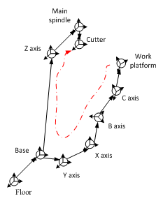
Anchor object contains a cartesian coordinate. It can be a mechanical component or a flag.
Branch object is a directional link between two Anchor objects. It contains the ITransformer object. The ITransformer object contains a coordinate transformation matrix. As shown in the following sketch:
Assembly Management
Asmb (Assembly) provides organization and management of Anchors. An Assembly can contain both Anchors and other Assemblies. Key features include:
- Grouping related Anchors together
- Managing coordinate transformations
- Providing display and indexing functions
- Supporting hierarchical structure
Mechanisms Own Their Topology
A mechanism (IMechanism) — the machine tool, the fixture, the workpiece — owns one assembly, a root anchor and the solids hung on its anchors (for the machine tool Asmb, Root; for the fixture Asmb, Root, AnchorToSolid; the same three on Workpiece). The topology inside is free: any anchors, branches and transformers. What ties a part to its neighbours is not a fixed slot but a role — a settable property of the mechanism naming one of its own anchors (a mount) or branches (an axis). The equipment attaches the roles of neighbouring parts to each other with branches of its own and rebuilds those attachments whole whenever a part or a role changes (Rewire(API)). Which roles each part names, and what meets what, is Assembly Anchors.
A transformer therefore lives on a branch, and the way to reach one between two known anchors is
Get(API): Branch.Get(fixture.GeomAnchor, fixture.TableMount).Transformer.
Kinematic Chain Example
The following figure shows a kinematic chain of a non-orthogonal 5-axis machine tool:
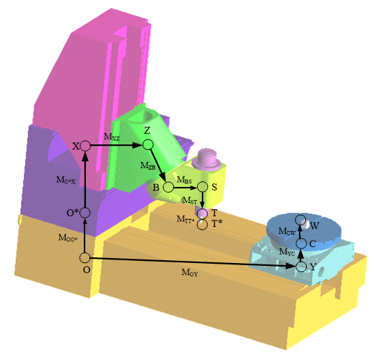
Each Anchor represents a component:
- Axis components: X, Y, Z, B, C
- Base components: O (base1), O* (base2)
- Tool components: S (spindle), T (tool body), T* (tool flute)
- Workpiece: W
The relative transform between two Anchors is calculated by multiplying the transform matrices along the Branch. For example, the transform matrix from W to T is:
This matrix can be obtained using TryGetMat4d, which answers false when no chain of branches connects the two anchors.
Error-Term Branches
A branch of the machine tool's own topology can be marked as an error term (IsErrorTerm): it carries an error of the real machine, such as a squareness, a tilt or a pivot offset, not part of the machine's design. The controller — the kinematics solver XyzabcSolver, which turns NC and CL positions into machine coordinates — always solves on the nominal chain: the same topology with every marked branch taken as NoTransform, so that in a product like the one above a marked branch counts as the identity. The machine that moves, cuts and collides runs with the marked branches while the project's error-term switch is on, and without them while it is off. The machine coordinates of every step are the same either way; with the switch on, the error is cut into the part, the way a real controller that does not know its machine's errors cuts it.
Adding an error term to an axis or the spindle and switching the error terms in the application are described in Building Virtual Machine Tools, the cards of a role branch and of its error term, with their refusals, in Equipment Topology Column, and the geometric errors of a real machine that the model leaves out in Machine Geometric Error.
The Nominal Chain and the Machine
| Reader | Chain it reads | Follows the switch |
|---|---|---|
The controller: NC programs, including RTCP (G43.4, TRAORI, M128) and tilted work planes (G68, G68.2, CYCLE800, PLANE); CL (CLSF) playback on a machine chain; the NC-optimization write-back |
the nominal chain | no — always nominal |
| The runtime face (MachiningEquipment, the equipment a run moves): motion, cutting, collisions, the Execution canvas, the CL step property (Cl, the actual tool tip in program coordinates) | the authored errors while the switch is on; the marked branches as No Transform while it is off | yes |
| The authored face (SetupEquipment): the Equipment canvas, the saved project and machine files | the authored values | no |
| The program-zero measurements (below) | the nominal chain at machine zero | no |
A CSV program takes its machine coordinates from its records, and with the switch on the machine
moves them with its errors. On a ClMillingDevice nothing is solved: the cutter location is applied
straight to the tool.
With the switch on and with it off, each step's machine coordinates are identical; what differs is the tool tip, the CL step property, the actual tip feed rate, the cut geometry, forces and heat, and collisions. The set of steps can differ too, since a step is made where the actual tip moves, so compare two runs by end time code (EndTimecode) or by machine coordinates, never by step index (StepIndex).
The switch is EnableErrorTerms, on by default
(Enable Error Terms on the Machine Tool item of the Control Tree). It belongs to the project: the
project file saves it as the <EnableErrorTerms> element, a project file without the element reads
as on, and the machine file does not carry it. On a loaded project, write
EnableErrorTerms, which rebuilds the runtime face at
once when no run session is open and otherwise at the next boundary (the next play's start, a new
session, a Reset); writing the config property alone starts no rebuild, and the value takes effect
when the runtime face is next rebuilt. No mission or script command flips the switch. Off, the
marked branches of the runtime face are No Transform, so the machine cuts like one without error
terms; the Equipment canvas still draws the authored values, and the marks stay.
The program-zero measurements — P0 on a Work Coordinates row (Set to the machine position at
program zero), the Heidenhain datum at the table mount's zero, the program-zero alignment and the
work-coordinate marker — measure on the nominal chain at machine zero. Their answers depend neither
on the switch nor on which face they read, so aligning and then pressing P0 returns to the same
offset. A touch-off on a real machine finds a work offset that already holds the shift the
machine's errors cause with every axis at zero, whereas P0 gives the nominal value and leaves
that shift in the cut too; to reproduce a
given shop's result, type that shop's measured work offset (G54 …) by hand — see
Program Zero Alignment.
What an Error Term Can Express
An error term holds a constant transform, so it expresses constant errors: the squareness between linear axes, the tilt of an axis, a rotary axis' pivot offset, an offset of machine zero, the tilt of a spindle housing. Errors that vary with position — pitch and scale errors, straightness, a volumetric error table — cannot be expressed, and neither can reversal and backlash, servo mismatch or thermal growth.
Where an Error Term Goes
An error term belongs to an axis or the spindle of the machine tool and stands in series just before that role's branch. The Topology column of the Equipment page adds one there and nowhere else: the card of a branch that plays Axis X … Axis C or Spindle carries an Error term option, which inserts the error term in front of the branch in one edit and, switched off, takes it out again. No other branch's card offers a mark.
The place. A branch F → E stands as the error term of an axis or the spindle when the branch R = E → A that the role is bound to follows it and all of the following hold. The editor builds this shape when it adds an error term and reads every mark against it, wherever the mark comes from. Most of the conditions are what lets the error term go again cleanly: removing it deletes E and F → E and runs R from F once more.
| The place requires | Because |
|---|---|
| F → E is a branch of the machine tool's own topology | An error term is an error of the machine, and the controller's model is the machine tool's own chain; a fixture or a workpiece has no axis to own one. |
| F → E plays no role | A role branch cannot be an error term (Role Branches); and an axis branch a file marks, standing before another axis, would otherwise read as that axis's error term, and removing that error term would take the first axis's branch out. |
| F → E carries a static kind — Static Translation, Static Rotation, Static Freeform, General Transform or No Transform | An error holds a fixed value, and no axis drives it. |
| F → E is the only branch into E | With a second branch into E, F → E is not the one segment before R, and removing it would leave the other branch with nowhere to arrive. |
| E is not the root, plays no role and hangs no solid | Removing the error term would delete a mount or a shape with E, and the root cannot be deleted at all. |
| Nothing leaves E but R | Every other branch leaving E would be cut off when E goes. |
A static kind. The error term the editor inserts carries a Static Rotation of 0° about (0, 0, 1), so the machine stays as it was until the error's value is entered. Its kind can be changed to any of the static kinds. A dynamic kind (Dynamic Translation, Dynamic Rotation) is refused: a marked branch is not given one, and a branch that carries one is not marked.
Not between the spindle and the tool mount. There an error term would make the spindle read as off the tool axis, so no mark is set on a branch between the spindle branch and the tool mount, and no error term is added to a role whose branch lies there, since the branch before it would lie there too. A spindle housing's tilt is the spindle's error term, before the spindle branch: on a three-axis machine between Z and the spindle branch, on a B head between B and the spindle branch.
In series, on a branch of its own. Only one branch may run between a pair of anchors in one
direction, so an error term needs an anchor of its own that splits the segment before its axis in
two. On a C axis that hangs from Z, for example, adding Axis C's error term makes a new anchor
Cerr and the marked branch Z → Cerr, named Cerr as well, and runs the C axis' branch from
Cerr to C; a pivot offset of the axis is then entered on Z → Cerr as a Static Translation. A
branch's two ends are fixed, so the axis' branch is rebuilt rather than moved: a new branch takes
over the old one's transformer object, name and roles, under a Guid of its own, and removing the
error term rebuilds it once more from Z. The anchor is named after the role's branch with err
added — after the anchor the branch reaches when the branch has no name — and takes a three-digit
number, as in Cerr001, when an anchor of the machine has that name already. It adds a word to the
machine's chain code, [Z][Cerr][C] (Machine Chain Code), and without a shape it
takes part in no collision pair.
Later edits. The place is made when an error term is added and checked when a mark is set again
over the HTTP API. A later edit that breaks it — binding the axis to another branch, giving the
anchor a shape or a mount role, adding a branch into or out of the anchor — is not refused: the mark
stays, and the Roles panel
reports it as no axis's or spindle's error term (ErrorTermNotOnRole), or as lying between the
spindle and the tool mount (ErrorTermOnToolAxis). The role and kind rules hold on every edit: no
role is bound to a marked branch, and no marked branch is given a dynamic kind.
In code, IsErrorTerm takes a mark on any branch; only a marked role branch is refused, where the chain is solved and where a run starts. Hold to the same shape there — a static branch of its own just before an axis or the spindle, into an anchor of its own — so that the editor reads the mark as that role's error term.
What the Controller Sees
Where an error sits decides what a mark changes, because the machine coordinates a controller solves depend on only part of the chain:
| Error | Unmarked | Marked |
|---|---|---|
| A translation T between the last table-side rotary axis and the table mount | Invisible to the controller anyway: it only moves the workpiece's coordinate origin, like placing the workpiece elsewhere. For the same work offset, the machine coordinates are those of the machine without it, and the CL step property is offset by −T. | The same; the mark matters only for the switch. No axis follows this place, so the editor adds no error term here. |
| A translation before a rotary axis (a pivot offset), a squareness between linear axes, a tilt between rotary axes, a translation on the tool side | Seen by the controller as part of the machine: under RTCP or a tilted work plane, the machine coordinates follow it. | The machine coordinates return to those of the machine without it, and with the switch on the error stays in the part. |
In plain mode — no RTCP, no tilted work plane — the machine coordinates do not depend on the chain at all, so every chain error, marked or not, is cut into the part.
Role Branches
A role branch — Axis X … Axis C or the Spindle of a machine tool, the key branch of a CL device
(KeyBranch) — cannot be an error term: with the switch
off the role would silently stop moving, and an axis would drop out of the controller's model either
way. On a machine tool the editor offers no mark on a role branch: its card adds an error term in
series before it instead, and a mark asked for over the HTTP API is refused (ErrorTermOnRole).
A CL device is not edited in the Topology column, and the HTTP API refuses every edit of it
(MechanismNotEditable). A mark a file brings in is refused by name:
- on a machine tool, the Roles panel reports
ErrorTermRole, and the controller refuses the chain: the session reportsSession-MachiningChain--ErrorTermRole, and no machine coordinates are converted until the role is repaired, though the project still loads; - on either kind of chain, a run — an NC, CSV or CL play, or a session script's
PlayAct,
PlayToolingTeleport or
PlayClTeleport — stops at its start with an
ErrorTermRoleException naming the role (Role)
and the branch (BranchName: its name, or
fletch--->arrowwhen it has none); played from the mission list, that stop is reported asPlayer-Run--Fault.
The check is RequireRoleBranchesNotErrorTerm(API); code can run it on a chain before a run does. The repair is to clear the mark and put the error on a branch of its own in series with the role branch: on a machine tool, with the role branch's card (Clear mark, then the Error term option); on a CL device, which the Topology column does not edit, in the file or in code. RoleBranchName is set only when the controller finds an axis's transformer object moved onto a second branch that is marked, the axis's own branch still in place; the repair then is to put the transformer back on the role branch.
In Files and in Code
A machine or project file stores the mark on the branch element as IsErrorTerm="true", written only
when true; a file without the attribute reads as unmarked. The attribute is read leniently: true
and false in any letter case, 1 and 0, with spaces around them. Any other value loads the
branch unmarked with a Branch-IsErrorTerm--Unreadable warning naming the branch, its Guid and the
text read, and the project still loads. A chain code does not show the mark; assigning one carries a
branch's mark over with its transformer (Machine Chain Code).
The editor reads a file's marks by the same place rule (Where an Error Term Goes): a mark in that place is its axis's or the spindle's error term — a segment split by hand into that shape reads as one, with nothing rebuilt — and any other mark on the machine tool, a fixture or a workpiece is reported on the Roles panel, whose finding the branch's card repeats beside a Clear mark button that takes the mark off.
In code the mark is a property. The pivot offset above, on a machine built from chain code:
GeneralXyzabcMachineTool machine =
    GeneralXyzabcMachineTool.CreateFromChainCode("[O][Z][Cerr][C][w];[O][Y][X][B][S][t]");
Branch pivotOffset = Branch.Get(machine.CodeToAnc["Z"], machine.CodeToAnc["Cerr"]);
pivotOffset.Transformer = new StaticTranslation(0.005, 0, 0); // the C axis 5 µm off in X
pivotOffset.IsErrorTerm = true;
See Also
- Machine Chain Code — the bracket notation that writes this same connectivity down for hand-editing
- Assembly Anchors — the roles each part names, and the mount anchors a machining scene is assembled at
- Handle Transform Matrix by ITransformer — what sits on each branch and moves it
- Render Topology — drawing an assembly through the anchors defined here