Deep slot in AA7050, plunge against layer roughing: with the Z axis 0.003° out of square, both walls lean toward +Y together, 3.9 µm at 74 mm deep, and the two roughing strategies cut the same slot (3-axis)
- Original source
- Slot, tool and cutting conditions: F. J. G. Silva, R. P. Martinho, L. L. Magalhães, F. Fernandes, R. C. M. Sales-Contini, L. M. Durão, R. C. B. Casais, V. F. C. Sousa, A Comparative Study of Different Milling Strategies on Productivity, Tool Wear, Surface Roughness, and Vibration, Journal of Manufacturing and Materials Processing 8(3), 115 (2024), doi:10.3390/jmmp8030115. The article publishes no CAD model, NC program or data set; every value the case uses comes from its tables, figures and text. Its machine is a HAAS VF2, which the case does not model.
- Search keywords
A Comparative Study of Different Milling Strategies on Productivity, Tool Wear, Surface Roughness, and Vibration,jmmp8030115,plunge milling deep slot AA7050-T7451- Licence
- The article is under CC BY 4.0. Its licence statement reads: "Copyright: © 2024 by the authors. Licensee MDPI, Basel, Switzerland. This article is an open access article distributed under the terms and conditions of the Creative Commons Attribution (CC BY) license (https://creativecommons.org/licenses/by/4.0/)." From the article the case takes, through its base case, the slot's dimensions, the tool and the cutting conditions only: none of its measured times, vibration, wear or roughness values, and no figure or photograph is reproduced. Every picture here is a HiNC capture or a chart drawn from HiNC's results. The block, the slot's position, the vise, the NC programs, the tool's unstated geometry and the machine were derived or chosen for the base case, and the error for this case; the error's size and direction are not a measurement of any machine.
- Attribution
-
As the base case's source record gives it:
Slot geometry, tool, cutting conditions and measured values after F. J. G. Silva, R. P. Martinho,
L. L. Magalhães, F. Fernandes, R. C. M. Sales-Contini, L. M. Durão, R. C. B. Casais, V. F. C. Sousa,
"A Comparative Study of Different Milling Strategies on Productivity, Tool Wear, Surface Roughness, and
Vibration", J. Manuf. Mater. Process. 2024, 8, 115, https://doi.org/10.3390/jmmp8030115, © 2024 by the
authors, licensee MDPI. Licensed CC BY 4.0 (https://creativecommons.org/licenses/by/4.0/), provided
as-is without warranties (CC BY 4.0 Section 5). No endorsement by the authors or MDPI is implied.
Changes: nothing in the article; the block, the slot, the vise, the NC programs and the tool's unstated
geometry were derived or chosen for this case (see What we changed).
What we changed, in that record: nothing in the article; the block, the slot's position, the vise, the three programs, the tool and its holder, the machine and the spindle were derived or chosen for the base case.
Tech Coordinate's agent added one error-term branch to the simulated machine and chose its kind, its size, its direction and its pivot. Neither the authors nor MDPI endorse Tech Coordinate, HiNC or this case. - About the case
- The base case rebuilt the paper's set-up in HiNC: the 40 × 150 × 150 mm block standing upright in a single-station vise between two 20 mm steel side blocks; a closed slot 12 mm wide, 140 mm long and 74 mm deep, finished to 12.6 mm; a D12 three-flute solid carbide end mill 85 mm out of an ER32 collet chuck, about seven diameters; and three Fanuc programs the agent wrote because the paper publishes none: 28 full-depth plunges 4.741 mm apart (plunge roughing), 20 layers of 3.7 mm along the slot (layer roughing), and the same finishing after either, five levels of 14.8 mm at 0.3 mm per side. The machine is HiNC's three-axis skeleton: the table carries X and Y, the head Z. That base case has no page of its own; the full record of this case cites it. Here the machine gets one constant geometric error: its Z axis is out of square with Y by 0.003°, that is 15.7 µm per 300 mm, a typical value the agent chose; the paper measured no machine geometry.
The story
A 2024 paper by Silva and colleagues roughs a closed slot in an AA7050 block, 12 mm wide, 140 mm long and 74 mm deep, two ways: by full-depth plunges side by side, or by layers along the slot. After either it finishes the walls to 12.6 mm in five levels, the same way, and compares machining time, tool wear, roughness and vibration. The tool is a D12 three-flute carbide end mill 85 mm out of an ER32 collet chuck, about seven diameters. The base case rebuilt that test in HiNC from the paper's tables and photographs and wrote the three programs the paper does not publish. On the shop floor the question runs the other way: the walls of a deep slot measure out of square, and would another roughing strategy help?
Here an AI agent gave the base case's three-axis machine one common geometric error: its Z axis is out of square with Y by 0.003°, 15.7 µm per 300 mm, a typical squareness for a linear axis; the paper measured no machine geometry. The error sits on a branch of the machine marked as an error term, directly upstream of the Z axis. This skeleton machine binds no spindle role, so the column and the spindle tilt together, and the tool tip moves 0.05236 µm toward +Y for every millimetre it goes down. The pivot is the point where the tool tip stands at the touch-off, the centre of the stock top: there the deviation is 0, and the case's own G54 is the one a real touch-off would find. The controller solves its axes as if the branch were not there, while the simulated machine moves and cuts with it whenever the project's Enable Error Terms switch is on. The agent changed no line of the programs.
Before the first play, the agent wrote down the tool-tip offset it expected, the deviation of every feature, seven pass criteria and one prediction above all: both routes end with the same slot, its walls parallel and leaning 3.9 µm at the bottom, its width unchanged, with no step between the finishing levels. A trimmed case, the first five plunges and one finishing loop, played first, to check the build and the formula. Then each route played whole at 0.25 mm, geometry only, three times:
- error terms off: the nominal cut, which every comparison of that route is measured against;
- off again, with HiNC's geometry difference (Diff) against the nominal cut: the noise floor;
- on, with the error marked, so the controller does not know it.
The programs are plain three-axis work: G54 and G43, with no RTCP, tilted plane or CL. Their machine coordinates come from the program and its offsets alone, so a controller that knew the error would compute the same machine coordinates and cut the same leaning slot; that is reasoning, and no run was played to show it. A real three-axis controller removes such an error only through its own squareness compensation, which HiNC does not simulate here.
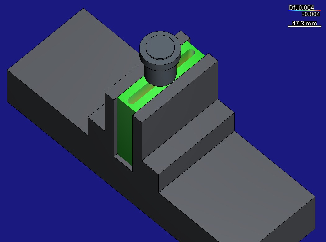
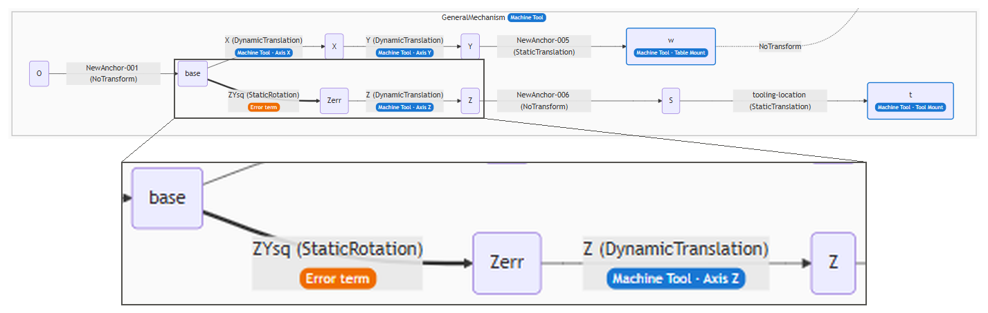
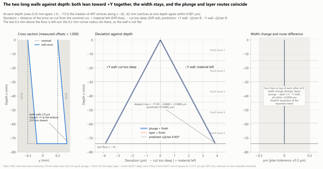
HiNC rendered these pictures from the block, the vise, the tool and the programs the base case derived from the paper; no figure or photograph of the article is reproduced. The colours are HiNC's geometry difference (Df in the colour bar) against the cut of the same route's nominal run, on a symmetric scale of ±0.004 mm: red = cut too deep, blue = material left, green = 0. The pictures were taken with the recorded stock and its Diff put back on the canvas, not from a replay; for the first picture, a pose program brought the tool into view. The chart is drawn from the meshes of the cuts HiNC exported. Grid 0.25 mm.
| Key number | What it is |
|---|---|
| 0.003° | the error: the Z axis out of square with Y by 0.003°, 52.36 µrad, or 15.7 µm per 300 mm. It is a typical size the agent chose, not a measurement; the paper measured no machine geometry. The tool tip moves 0.05236 µm toward +Y per millimetre of depth, from 0 at the stock top, where the touch-off is made |
| 1.51×10⁻¹³ mm | the largest gap over the 73,771 cutting steps of the three runs with the error between the measured tool-tip offset and the formula written before the first play, δ = (0, −Zp·sin θ, −Zp·(1 − cos θ)) with Zp the tip's program Z. That gap is effectively zero. The offset is 0 at the stock top and 3.875 µm toward +Y at the slot bottom, Zp −74; the machine coordinates equal the nominal run's at every step |
| ∓3.849 µm | the two long walls at z −73.5: the +Y wall −3.849 µm (cut too deep), the −Y wall +3.849 µm (material left), along −|z|·tan θ and +|z|·tan θ, 0.05236 µm per millimetre of depth. The five finishing bands read ∓0.399, 1.165, 1.937, 2.710 and 3.475 µm, each within 0.0005 µm of its prediction on the same vertices |
| 0.0005 µm | the largest gap between the walls and the prediction, which is the spacing of the exported mesh's single-precision coordinates at y 6.3 mm. The slot's width changes by at most 0.0005 µm (median 0.000), and the four joins between the five finishing levels show no step (0.0001 µm or less) |
| 0.000 µm | the difference between the plunge and the layer route in the median of each of the ten wall bands. 468,295 vertices of the two cuts are identical bit for bit in position and distance; the only differences are 464 floor vertices in the rows y −5.75 and −5.5 on the −Y side, by at most 0.0153 µm, and 183 extra vertices of the plunge mesh on the stock top, at distance 0 |
| ±0.30 µm | the floor, tilted across its width from −0.30 µm at the −Y edge to +0.30 µm at the +Y edge, following each pass's own tool bottom rather than one rigid rotation; measured within 0.01 µm of the pass-by-pass prediction |
| 2 h 14 min | server time for the nine plays at 0.25 mm on the shared 32-thread server: three trimmed and six whole, 35,533 steps per play on the plunge route and 38,971 on the layer route, 926–1,752 s each while other cases ran beside them. The heaviest whole play peaked at 2.37 GB (2.21 GiB) of memory |
Four of its seven dilemmas
A hypothesis that fails before the first play
The brief to the design agent said that plunging and layering would leave different walls. That takes a machine whose Z travel is tilted while its spindle stays true to the table: each 14.8 mm finishing band would then be vertical but shifted with its depth, leaving steps of 0.78 µm between the levels. This skeleton machine binds no spindle role, so a spindle tilt of its own cannot be placed on it; the only error that fits tilts the Z travel and the tool together. Then a point on the wall at depth z moves |z|·tan θ toward +Y whatever pass cut it, a plunge wall, a layer's flank or a finishing level, and the walls of both routes land on the same tilted planes. The agent turned the case into a pre-registered equivalence experiment: the plan, committed before the first play, predicts that both routes end with exactly the same slot, with 0.3 µm of tolerance per band. Measured, the ten bands differ by 0.000 µm and the joins between the levels by at most 0.0001 µm.
Where the pivot goes, so that G54 need not change
A static rotation needs a pivot, and where it sits decides whether program zero moves. Left at the machine origin, the error would push program zero 32.7 µm toward −Y. A real touch-off would absorb that into G54.Y; HiNC's program-zero measurement, made on the nominal machine, would not. The runs would then disagree on G54, and the Diff would charge the missing touch-off to the error. The agent put the pivot where the tool tip stands at the touch-off, the centre of the stock top. There the deviation is 0, the case's own G54 is what a touch-off finds, and every run used it unchanged. The offset a fit finds at program zero is at most 1.13×10⁻¹⁴ mm, and the deviation grows with the tip's height above or depth below that point, to −11.5 µm at the machine's home position, 220.5 mm above it, where nothing is cut.
A floor that is not one rigid rotation
To first order, the plan read the error as the whole cut turning about one line along X through the centre of the stock top; read literally, the floor would be a plane through 0 at y = 0. The design's feature prediction took the floor from the last finishing pass at Y +0.3 instead: −0.304 µm at y −5.5. The floor read neither: −0.0153 µm at y = 0 and −0.290 µm at y −5.5. The pivot is fixed on the spindle line while the table carries the part under it, so in program coordinates each pass tilts about its own Y position: the tool bottom of the pass at Y +0.3 sits (y − 0.3)·tan θ above nominal, and each point of the floor keeps the lowest of the passes that swept it. That pass-by-pass model matches the measured floor within 0.01 µm, where the mesh's single-precision spacing is 0.0076 µm. The one-line picture is exact only for passes at Y 0; for the walls it holds to within 0.00001 µm, which is why the walls agree with it and the floor does not.
Readings of −180 µm that are not the error
Against the nominal cut, 542 of the 468,942 vertices of the plunge route's cut read beyond 5 µm, down to −180 µm, 46 times the most this error can do. All sit at the edge of the floor: 521 in the row next to the −Y wall and 17 in the floor corners of the slot ends, at z −74, and 4 in the +Y end corners, on the 0.2 mm corner radius just above. The same vertices read the same values on the layer route, and none lies in a feature box the design judged. The distance search looks only at the 12 nearest triangle centres and can overstate a distance beside large triangles, so each of the 542 was recomputed as an exact point-to-triangle distance: all are real differences between the two meshes, within 10⁻⁵ µm of the search. The analysis infers that they are not a cut: the tool kept its shape and its tip never moved more than 3.875 µm at any step, so no face can be cut 62 µm deeper. Why the meshes differ there is inferred too: the nominal floor lies exactly on a grid plane and the 0.2 mm corner radius is smaller than the 0.25 mm cell, so the 0.3 µm dip of the floor's −Y side flips that row of cells and the exported vertices land on the grid instead of on the corner's arc.
The full record has the other three: whether a 0.25 mm grid can read 3.9 µm (it reads the walls to 0.0005 µm); three traps in the base case's mission and play script, a list whose resolution differed from the others, stock-record entries after the roughing, and a script that skips the roughing and reads a cached stock when one exists; and why the canvas shows the long walls of a closed slot only at a grazing angle, so that a chart carries the main evidence. It also notes that the control runs exported no cut of their own, so the plan's noise-floor criterion could not be judged as written: their step series are identical to the nominal runs', and their Diff is green but for a few sampling specks on the slot-end arcs seen from above, which the runs with the error show too.
The result
All nine plays ran to the end, 4,103 steps per trimmed play, 35,533 per whole play on the plunge route and 38,971 on the layer route, with no collision, no rapid move through stock and no travel alarm. Five of the seven criteria written before the first play passed as written. The build criterion passed in every part the records cover, but two of its items, a reload of the error-term project without a load message and the case's other files left unchanged, were not recorded; the noise-floor criterion could not be judged as written, as told above.
With the controller unaware of the error, the tool tip of each of the 73,771 cutting steps of the three runs with the error sat where the formula written before the first play put it, the largest gap 1.51×10⁻¹³ mm: 0 at the stock top, 3.875 µm toward +Y at the slot bottom, the same wherever the table stands in X and Y. The machine coordinates of every step equal the nominal run's.
On the part, both long walls shift toward +Y by |z|·tan θ: the +Y wall is cut too deep and the −Y wall keeps material, from 0 at the rim to ∓3.849 µm at z −73.5, with no step between the five finishing levels and the width unchanged within 0.0005 µm. The floor tilts across its width from −0.30 to +0.30 µm, following each pass's own tool bottom. The R6.3 slot ends carry the same shift: near the bottom they read +3.8 µm where they meet the −Y wall, 0 at the apex and −3.8 µm where they meet the +Y wall. The stock top and the block's outer faces read 0.
The plunge route and the layer route cut the same slot: on the walls, every vertex of the two cuts is identical bit for bit, and the medians of the ten wall bands differ by 0.000 µm. The finishing takes 0.3 mm off each wall and removes whatever the roughing left, and every pass, roughing or finishing, shifts by the same amount at the same depth. So the prediction written before the first play held.
The study models this one error only, constant, and the agent chose its size and direction; with the tilt the other way, the +Y wall would keep material and the −Y wall be cut too deep. The plays are geometry only, with no cutting force or deflection: the real walls would add the bending of this seven-diameter cutter to the lean. Everything is simulated; no slot was cut.
What it brought
- For a machining engineer: a Z axis only 0.003° out of square with Y, 16 µm per 300 mm, makes the two walls of a 74 mm deep slot lean together: the +Y wall ends 3.9 µm too deep at the bottom, the −Y wall keeps 3.9 µm of material, the width is unchanged, and the slot's centre drifts 0.052 µm toward +Y per millimetre of depth. The squareness is common to every pass: plunges, layers and the five finishing levels all cut on the same tilted Z, and the finishing copies the lean as it is. Switching between plunging and layering does not remove it; recalibrating the machine or the controller's squareness compensation does. The shape of the walls tells the source apart: two walls leaning in parallel, one too deep and one with material left, with the width intact, is the fingerprint of a machine squareness. The touch-off point is the zero of the deviation: touched off on the stock top, the top does not move and the deviation grows with depth. In HiNC, a constant error measured on a machine can go into its model, which shows what it does to your own part, and how much, before anything is cut.
- For a teacher or a student: how a small angle upstream of the Z axis becomes the tool-tip offset δ = (0, −Zp·sin θ, −Zp·(1 − cos θ)), and why it depends on depth alone, not on X or Y. Why a point on the wall shifts by its own depth whatever pass cut it, so the roughing strategy and the number of finishing levels make no difference, while the floor still shows each pass's own tilt. A pre-registered prediction, "both routes are the same", written before the plays and then tested with two of them. And how a 0.25 mm voxel grid reads plane offsets of 0.4–3.9 µm to 0.0005 µm, and where it misreads: the floor's edge and the faceted end arcs.
- For someone deciding whether to use an agent with HiNC: the study went from the base case's programs to one machine error's effects in nine plays and 2 h 14 min of server time, the six whole plays taking 7,428.6 s. The predictions were written before the first play; the largest gaps were 1.51×10⁻¹³ mm on the tool tip and 0.0005 µm on the walls, and the two routes came out identical bit for bit on the walls. Where the plan's wording missed, as with the floor's rigid rotation, where a reading is real but its cause only inferred, as with the 542 floor-edge vertices, or where a measurement could not be made, as with the control runs' cut, the record says so.
Read the full case record: the deep slot with the Z axis 0.003° out of square
How the block, the vise, the tool and the three programs were rebuilt from the paper is told in that record; the base case has no page of its own.