Plunge against Layer Roughing of a Deep Slot on a Z Axis 0.003° Out of Square: Both Walls Lean toward +Y, 3.9 µm at 74 mm Deep, and Both Strategies Cut the Same Slot
Silva et al. (Journal of Manufacturing and Materials Processing 8, 115, 2024) roughed a closed slot 12 mm wide, 140 mm long and 74 mm deep in an AA7050 block, then finished its two walls to 12.6 mm. The tool was a D12 three-flute solid carbide end mill reaching 85 mm out of an ER32 collet chuck, about seven diameters. The paper compares two roughing strategies, full-depth plunging (PM) and layers along the slot (TM), each followed by the same five-level finishing. An AI agent rebuilt the block, the vise, the tool and the holder in HiNC from the paper's tables and photographs, and wrote the three programs itself: the paper gives no NC.
The shop floor often asks a different question: the walls of a deep slot measure out of square, so would another roughing strategy help? On this page the agent sets the Z axis of the case's three-axis skeleton machine 0.003° out of square with Y, 15.7 µm per 300 mm, a typical squareness for a linear axis, as one marked error term directly upstream of the Z axis. Not one line of the programs was changed. Each of the two routes was played three times at 0.25 mm:
- Error terms off: the nominal run. Its cut is the ideal geometry of every geometry difference (Diff) that follows on the same route.
- Error terms off again, with a Diff: the control run, for the noise floor.
- Error terms on, the error marked: the controller does not know the error. The programs are plain three-axis ones, so the error is cut into the part whether it is marked or not, and no unmarked run was played.
A trimmed set, the first five plunges and one short finishing loop, came first, to check the build and the per-step formula. The prediction the plan wrote down before the first play: both routes end with the same slot. What came out:
- The tool tip. The three on runs have 73,771 cutting steps in all (trimmed 3,219, plunge route 33,262, layer route 37,290). On every one of them the tip's offset lies on δ = (0, −Zp·sin θ, −Zp·(1 − cos θ)) within 1.51 × 10⁻¹³ mm, where Zp is the tip's program Z. The offset depends on depth alone: 0 at the stock top, where the touch-off is made, and 3.875 µm toward +Y at the slot bottom, Zp −74. Every step's machine coordinates are the nominal run's.
- The two long walls shift together toward +Y by |z|·tan θ. The +Y wall is cut too deep and the −Y wall keeps material; their slopes are ±0.05236 µm/mm (predicted 0.05236), within 0.0005 µm of the prediction, and at z −73.5 they read ∓3.849 µm. There is no step between the five finishing levels (≤ 0.0001 µm), and the width does not change: the two walls' deviations add up to at most 0.0005 µm.
- The two routes. In the plunge and the layer cut, every wall vertex has the same position and the same distance, bit for bit, and the ten wall bands' medians differ by 0.000 µm. The whole part differs in two places only: two rows of floor vertices, by at most 0.0153 µm, and 183 vertices on the stock top, all at a distance of 0, that only the plunge mesh has.
- The floor and the other faces. The floor tilts with the tool's bottom, from −0.30 µm at one side to +0.30 µm at the other; the stock top and the block's outer faces read 0.
- The control. Its tool tips and machine coordinates equal the nominal run's at every step. Its Diff is all green in the two oblique views, and the top view shows only a few scattered sample dots on the slot's end arcs, in the on and the off run alike. The control runs exported no cut, so the plan's control criterion could not be judged as written.
- The cost, on a shared 32-thread server: 4,103 steps and 155–261 s per trimmed run; 35,533 steps (plunge route) or 38,971 steps (layer route) and 926–1,752 s per full run, at a peak memory of 1.52–2.37 GB.
Everything here is simulated; no part was cut.
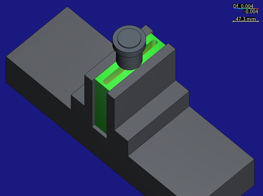
The stock the plunge route's on run (error marked) recorded, put back on the canvas with its Diff,
and the pose program pose-pm.nc played on it, which stops the tool at plunge 15 at full depth. The
ER32 collet chuck and its nut stand about 11 mm above the stock top; the Ø11.2 neck and the D12 cutter
are down in the 74 mm deep slot, with the vise and the side blocks on both sides. The stock top and
the slot's mouth are green: the deviation lies deep, out of sight from this angle. Diff colour scale
±0.004 mm (red = cut too deep, blue = material left, green = 0, both signs weighted alike); 0.25 mm; a
HiNC 3.2.46 development build with error-term branches.
| The slot at 0.25 mm on a HiNC 3.2.46 development build with error-term branches | Predicted | Measured |
|---|---|---|
| Tip minus the nominal tip minus δ, the 73,771 cutting steps of the three on runs | 0 (the plan allowed 10⁻⁹ mm) | at most 1.51 × 10⁻¹³ mm |
| Tip offset toward +Y at the slot bottom, Zp −74 | 3.874631 µm | 3.874631 µm |
| Machine coordinates, on against nominal | the same | the same at every step |
| Long walls, slope against z, +Y / −Y wall | +0.05236 / −0.05236 µm/mm | +0.05236 / −0.05236 µm/mm |
| Long walls at z −73.7…−70, +Y / −Y wall | ∓3.757 µm | −3.757 / +3.757 µm |
| Long walls at z −5…−1, +Y / −Y wall | ∓0.157 µm | −0.157 / +0.157 µm |
| Step between the finishing levels | 0 | ≤ 0.0001 µm |
| Width change: the two walls' deviations added | −1.6 × 10⁻⁵ µm | median 0.000 µm, at most 0.0005 µm |
| Plunge route against layer route, the ten wall bands' medians | the same | 0.000 µm apart; every wall vertex the same, bit for bit |
| Floor across its width | a plane tilted by ±0.3 µm | −0.298 to +0.298 µm |
| Stock top and the block's outer faces | 0 | 0 |
| Control run against nominal, tip and machine coordinates | 0 | 0 at every step |
| Server time of the nine plays / peak memory of a full play | — | 8,050.0 s / 1.52–2.37 GB |
The case
The paper (source and licence below) deposits no data and publishes no CAD model or NC program: every value comes from its tables, figures and text. An AI agent built it into a HiNC project, the JMMP deep-slot case. It derived the block, the slot's position and the vise from the tables and photographs, built the tool from Table 3 and wrote the plunge, layer and finishing programs itself. That case has no page of its own here and was not taken through a full acceptance; the full runs on this page play its three programs to their last line (criterion 2). Its machine was built as designed, with no error. This page adds one geometric error to the same machine and asks two questions: what does a Z squareness of a common size look like on a 74 mm deep slot, and how large is it; and does the result change with the roughing strategy, plunging or layering? What the agent was given:
- The base case's project and programs.
- The stock, a 40 × 150 × 150 mm block, stands upright in a single-station vise, with a 20 mm thick
steel side block on either side. Program zero is at the centre of the stock top, with X along the
slot;
G54is (−381, −203, −375.5). - Tool T1, a D12 three-flute end mill: flute length 18 mm, a 0.2 mm corner and a Ø11.2 neck, in an ER32 / SK40 collet chuck. The tool length offset H1 is 155 mm, the holder's 70 plus the 85 mm stick-out. At full depth the nut stands about 11 mm above the stock top.
- Three Fanuc programs, all plain three-axis ones (
G54,G43 H1,G00/G01, withG03round the slot's ends in the finishing), with no RTCP, no tilted plane and no CL:pm-rough.nc: 28 full-depth plunges 4.741 mm apart, from x +64 to −64. Each starts 1 mm above the stock top, feeds at 0.14 mm per revolution down to Z −74 and retracts at rapid.tm-rough.nc: 20 layers of 3.7 mm along the slot, back and forth, each entered by a straight plunge at the slot's end.finish.nc: 5 levels of 14.8 mm, top down. Each level is one loop round the slot, the tool centre at Y ±0.3 withG03arcs of radius 0.3 at the ends; both walls are climb-milled, 0.3 mm a side, at 0.07 mm per revolution.- For the trimmed runs,
trim-pm.nc(the first five plunges) andtrim-finish.nc(one finishing loop down to −14.8); for the pictures,pose-pm.nc(down to plunge 15, stopping at full depth).
- The stock, a 40 × 150 × 150 mm block, stands upright in a single-station vise, with a 20 mm thick
steel side block on either side. Program zero is at the centre of the stock top, with X along the
slot;
- The machine. HiNC's three-axis skeleton
Empty-wXYOZSt.default.mtfrom the resource library: the table moves in X and Y, the Y slide riding on the X slide, and the head moves in Z. It has no shapes and no spindle role bound. - What the paper did not measure: the machine's geometry. The paper names a HAAS VF2 with 10,000 rpm and 20 kW and measures no squareness of it; the machine's travels, spindle power curve and controller are not given either.
- HiNC's error terms. An axis or the spindle of the machine chain can be given an error term, a static branch of its own just before the axis's branch: it
carries a measured error rather than part of the design. The controller,
XyzabcSolver, which turns NC into machine coordinates, always solves on the nominal chain, taking the marked branches as absent. While the project's Enable Error Terms switch is on, the simulated machine keeps the marked branches as it moves, cuts and checks collisions. So the error is cut into the part, as on a real machine whose controller does not know it. Each step's machine coordinates are the same with the switch on and off; the tool tip, the cut and the collisions differ. Without RTCP or a tilted plane, every error in the chain is cut into the part, marked or not (Error-Term Branches). - Touch-off and P0. HiNC's P0 measures program zero on the nominal chain. On a real machine,
the
G54found by touching off already holds the constant shift the error causes at the touch-off pose. - A placement rule. HiNC's product owner ruled on 2026-10-06 that an error term goes only directly
upstream of a role branch, an axis X … C or the spindle, with one new anchor for each error, named
<axis>err. - The request. HiNC's product owner asked for error-term showcases built on earlier cases, product cases and paper cases alike, with the heavy runs on a shared server.
What nothing states:
- How far this machine's Z is out of square. The paper did not measure it. The agent took a typical squareness for a linear axis, 0.003°, and the direction “the Z travel and the tool turned about +X”.
- Where the error can go. The skeleton machine has no spindle role, and the ruling allows one error per role, so the only placement that fits is the Z travel and the tool tilting together (dilemma 1).
- Whether the suggested direction holds. The designer agent, the agent that drafted this study, was pointed at “plunging and layering leave different walls”. In the model that fits, that does not hold, even to first order (dilemma 1).
- Where the pivot goes so that
G54need not change (dilemma 2). - Whether a 0.25 mm grid reads a difference of a few micrometres (dilemma 3).
- The traps in the base case's mission, whose resolution and record entries were laid out for an acceptance with physics on (dilemma 4).
What is new here:
- A pre-registered equivalence experiment. One error, two roughing strategies, the same finishing. "The two routes' slots are exactly the same" was written down before the plays, and each route was played to test it.
- Depth as the amplifier. The deviation grows with depth and does not depend on x: a 74 mm deep inner wall turns 0.003° into 3.9 µm.
- The fingerprint of a machine's squareness. Both walls lean in parallel, one cut too deep and the other with material left, and the width stays.
- A floor that reads each pass's own tilt (dilemma 6).
What the agent built
Each value is marked read (from the base case or the build record), derived (computed from what was read) or chosen (the agent's decision). θ is the Z axis' squareness to Y.
| Value | Source | |
|---|---|---|
| Meaning | The Z travel is out of square with the table in the YZ plane: the Z axis' squareness to Y. This skeleton machine binds no spindle role, so the spindle tilts with the Z slide, as if the whole column and head stood tilted about X by θ. For every 1 mm the tool goes down, its tip moves 0.05236 µm toward +Y in program coordinates; at the stock top, the touch-off point, the offset is 0 | chosen: the kind of error and its direction; derived: the amount per mm |
| Size | θ = 0.003° = 52.36 µrad: 15.71 µm per 300 mm, 26.18 µm per 500 mm, 3.875 µm at 74 mm deep | chosen: a typical squareness for a linear axis (the plan: toward the upper end of a 5–20 µm per 300 mm range); the paper measured no machine geometry |
| Where | Directly upstream of the Z axis branch (base→Z), with a new anchor Zerr. base→Zerr is named ZYsq and carries a Static Rotation of 0.003° about (1, 0, 0), marked as an error term. The Z axis' Dynamic Translation (axis (0, 0, 1)) moved whole onto Zerr→Z, and Axis Z was bound to it again, with its values unchanged |
chosen: following the owner's ruling of 2026-10-06 |
| Pivot | (0, 0, 624.5) in base coordinates: the stock-top centre at the touch-off pose. In base it stays on the spindle line; it does not travel with the stock when the table moves in X and Y. O→base is a No Transform, so base coordinates are the machine root's |
derived: the stock top stands in base at the table's mount 390 + the vise's seat 84.5 + the block's 150. At the touch-off pose, machine (−381, −203, −220.5) (G54 plus H1 155), the tip stands at base (0, 0, 624.5) |
| The chain | Table side O→base→X→Y→w, tool side base→Zerr→Z→S→t |
read: the topology read back after the build |
| Work offset | All nine runs use the project's G54 (−381, −203, −375.5); nothing is typed in |
derived: the deviation at the touch-off point is 0 (dilemma 2) |
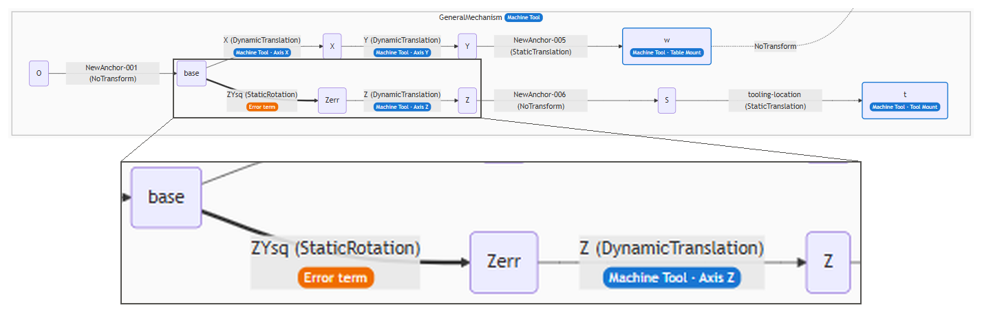
The machine-tool cluster (GeneralMechanism) in the Topology column of the Equipment page. The tool side runs base → Zerr → Z → S → t. ZYsq, in front of the new anchor Zerr (a Static Rotation of 0.003° about (1, 0, 0), pivot (0, 0, 624.5), the stock-top centre at the touch-off pose), is drawn thick with the orange Error term badge; the Z axis' Dynamic Translation now sits on Zerr → Z and is still the machine tool's Axis Z. The table side base → X → Y → w is untouched. Below, the stretch base → Zerr → Z magnified. This skeleton machine has no spindle role, so the Z travel and the tool tilt together. A HiNC 3.2.46 development build with error-term branches, English interface.
Where the tip goes: the prediction written in the plan.
- In base coordinates the tip is at (0, 0, MC.Z + 845): the tool mount is at MC.Z + 1000 and the tool is 155 mm long. The spindle line stays at x = y = 0; the workpiece sits on the other chain, carried by the table in X and Y.
- The error turns the whole tool side by θ about the pivot. From the pivot to the tip is (0, 0, Zp), where Zp = MC.Z + 220.5 is exactly the tip's program Z. The workpiece does not turn, so in program coordinates the offset is δ = R_X(θ)·(0, 0, Zp) − (0, 0, Zp) = (0, −Zp·sin θ, −Zp·(1 − cos θ)).
- δ does not depend on MC.X or MC.Y, only on depth. It is 0 at Zp = 0; δY is +0.775 µm at Zp −14.8, +1.937 µm at −37 and +3.875 µm at −74, where δZ is only 1.0 × 10⁻⁷ mm.
How far the part's faces move: the plan's prediction, the same for both routes.
- The two long walls (y = ±6.3) shift in parallel toward +Y by |z|·tan θ: 0 at the rim and 3.875 µm at the bottom, whatever x. The +Y wall is cut too deep and the −Y wall keeps material; over the five finishing levels the band means are ∓0.40 / 1.16 / 1.94 / 2.71 / 3.48 µm.
- Why there is no step between the levels, and why the strategy does not matter. The whole tool side turns together, so how far a point on the tool moves in Y depends only on its own height: a point at depth z moves |z|·sin θ toward +Y, wherever the tip is and whichever pass it belongs to. So the walls of the plunged holes, the side edge of every layer and the side edge of each of the five finishing levels all lie on one inclined plane. How far the tool's bottom moves in Z depends on its distance from the tool's centre, so the floor tilts with each pass (dilemma 6).
- The width does not change: 12·(sec θ − 1) is about 2 × 10⁻⁵ µm.
- The floor: a plane tilted by ±0.3 µm from one side to the other.
- The stock top and the block's outer faces: 0.
The runs:
| Run | List | Enable Error Terms | ZYsq |
Purpose |
|---|---|---|---|---|
| t-nominal | Trimmed PM | off | marked (not in effect) | trimmed: nominal; exports its cut (343,252 triangles) |
| t-control | Trimmed PM | off | marked (not in effect) | trimmed: control; the Diff, the stock recorded |
| t-on | Trimmed PM | on | marked | trimmed: on; the Diff, the stock recorded, its cut exported |
| f-pm-nominal | PM | off | marked (not in effect) | exports its cut (915,104 triangles), the plunge route's ideal geometry |
| f-pm-control | PM | off | marked (not in effect) | the Diff, the stock recorded; no cut exported |
| f-pm-on | PM | on | marked | the Diff, the stock recorded, its cut exported (468,942 vertices) |
| f-tm-nominal | TM | off | marked (not in effect) | exports its cut (915,104 triangles), the layer route's ideal geometry |
| f-tm-control | TM | off | marked (not in effect) | the Diff, the stock recorded; no cut exported |
| f-tm-on | TM | on | marked | the Diff, the stock recorded, its cut exported (468,759 vertices) |
Common to every run:
- A 0.25 mm grid: every machining-resolution entry of the mission, at the root and inside each list. Physics off, collision detection on, and the base case's motion resolution, one step per spindle revolution.
- The lists. “Trimmed PM” plays
trim-pm.nc, the first five full-depth plunges (x 64 to 45.04), thentrim-finish.nc, one finishing loop down to −14.8. “PM: plunge roughing, then finishing” playspm-rough.ncandfinish.nc; “TM: layer roughing, then finishing” playstm-rough.ncandfinish.nc. Each run enables its own list only. - The case's work offset. Every run used the project's
G54(−381, −203, −375.5); nothing was typed in. - The Diff (Geometry Validation): the ideal geometry is the
cut the same route's nominal run exported, with a detection radius of 1 mm and a colour scale
(
DiffVisualRadius) of ±0.004 mm. So the Diff shows only what the error changes, not the marks the toolpath itself leaves. - The recorded stock. The control and on runs recorded their final stock; the pictures put it back on the canvas with its Diff.
How the agent managed the work
- Criteria and predictions first. The plan, its predictions and seven criteria were committed before the first play: pushed at 21:23 on 2026-10-06, with the first run starting at 21:23:33.
- The build. At 21:22 on 2026-10-06 the agent's tools saved the base project as a new error-term
project, with a copy of its
NC/folder, and changed it through the web API only:ZerrandZYsqinserted and the branch marked; the Z axis moved and bound again; every machining-resolution entry, at the root and inside each list, set to 0.25 mm; physics off and collision detection on; the base case's four record entries disabled (dilemma 4); the motion resolution kept as in the base case, one step per revolution. - Trimmed runs first. The list “Trimmed PM” was played nominal, control and on, to check four things: the build, the per-step formula, that the machine coordinates equal the nominal run's, and the sign on the walls of the plunged holes. The layer route's trimmed program reaches only −14.8, where the deviation is just 0.77 µm, so it was not used. The three trimmed runs and the six full runs were queued as one background job: t-on ended at 21:34:28 and f-pm-nominal started at 21:34:33, so the trimmed results were not judged before the full runs began. The plan did not ask for that either.
- The two routes in full. “PM: plunge roughing, then finishing” (
pm-rough.nc+finish.nc) and “TM: layer roughing, then finishing” (tm-rough.nc+finish.nc), each played nominal, control and on, one run at a time. - A restarted instance for every run. All nine runs carry run id 1: each played on a freshly restarted instance that loaded the project from its file. So each VmHWM is that run's own peak.
- The ideal geometry is the same route's nominal cut. Each nominal run exported its cut, which became the ideal geometry of that route's Diffs. The Diff then holds only the error's difference, not the marks the toolpath itself leaves.
- The part's numbers from vertex distances. The on run of each route also exported its cut, and every vertex was given its signed distance to the same route's nominal cut. The control runs made a Diff and recorded their stock but exported nothing: when they played, the tools that drove the plays could not yet export a cut from a control run.
- Step by step. In every pair, on or control against nominal, the step count,
FileNoandLineNomatch at every step, so the series were lined up by step index and subtracted. - Every number from the records. The agent's analysis script computes the numbers on this page
from the run records, the captures and the last move line of each program in the base case's
NC/folder, keeps each number with its source, and can be run again; the exact distances of the extreme vertices were computed separately, against the nominal cuts. - Pictures in both interface languages, from the recorded stock put back on the canvas, not from a replay: the Diff from three cameras, two pictures with the holder in view, and the topology graph.
- Where a person stepped in. HiNC's product owner asked for error-term showcases built on earlier cases, product cases and paper cases alike, and ruled where an error term may go. The error, its size and direction, its pivot, the predictions and the criteria are the agents' own: the designer agent worked them out, and the agent that ran the case wrote them into the plan.
The criteria as committed before the first play:
| # | Criterion |
|---|---|
| 1 | Build: the error-term project reopens with no load message; ZYsq is a marked Static Rotation on base→Zerr; Axis Z is bound to Zerr→Z; the roles check is empty; the case's files outside the error-term folder are unchanged |
| 2 | Every run: Finished, more than 0 steps, contact (IsTouched) peaking at 1 and every program run to its end; no collision and no rapid move cutting; runs with a Diff add only Diff--TargetNotClosed |
| 3 | On (marked): on every cutting step, |Cl − Cl nominal − δ| ≤ 10⁻⁹ mm; the machine coordinates the same as the nominal run's, step by step (within 10⁻⁹) |
| 4 | Control: by vertex distance, at least 99 % of the vertices with |deviation| ≤ 0.2 µm |
| 5 | The slot, on against nominal, by vertex distance: the two long walls' median deviation ∓3.8 ± 0.3 µm at z −70…−74 and ∓0.15 ± 0.3 µm at z −1…−5; the median of the two walls' summed deviation within ±0.3 µm (the width unchanged) |
| 6 | The two routes: the long walls' median deviation in each finishing-level band differs between the plunge route's and the layer route's on runs by at most 0.3 µm (predicted: the same) |
| 7 | Cost: wall time and VmHWM recorded for every run |
The dilemmas
Each one is told as its situation, the risk if it had been missed, how it was noticed, the resolution, and the evidence that the resolution held.
1. “Plunging and layering leave different walls” does not hold in the model that fits
- Situation. The designer agent was pointed at the two roughing strategies leaving differently shaped walls. For a wall's shape to follow the way it was cut, with layers and finishing levels leaving steps, the error would have to be “the Z travel tilted, the spindle trammed square to the table”. Each finishing level's 14.8 mm band would then stand vertical but be shifted toward +Y as a whole by its depth, leaving steps of 14.8 mm × tan 0.003° ≈ 0.78 µm between the levels. Such a machine needs a tilt on the spindle role, or one tilt in front of Z and an opposite one in front of the spindle.
- Risk. This skeleton machine binds no spindle role, and the owner ruled on 2026-10-06 that an error term goes only directly upstream of a role branch, one per role. Holding to the first direction would have meant changing the base machine's roles, or a pair of errors the ruling excludes. Building the model that fits while still predicting “the two strategies differ” would have put a wrong prediction in writing before the first play.
- How noticed. While the designer agent derived the effect. The only placement that fits is one rotation upstream of the Z axis branch, with the tool tilting together with the Z travel. To first order, the design said, the whole cut in workpiece coordinates is turned by θ about the line through the stock-top centre along X; strictly, each pass turns about the X-direction line at stock-top height on its own spindle line (dilemma 6). A point at depth z on a wall moves |z|·tan θ toward +Y, whichever pass and whichever stretch of the side edge cut it (to first order; the difference is under 10⁻⁵ µm).
- Resolution. A pre-registered equivalence experiment instead. The plan states "the two routes' slots are predicted to be exactly the same" and “no step between levels”, and criterion 6 judges the two routes' bands to within 0.3 µm. The fingerprint of a machine's squareness, both walls leaning in parallel with the width unchanged, became criterion 5. A version with steps would first need the skeleton's Z→S bound as the spindle role, which is outside this case.
- Evidence. Every wall vertex is the same in both routes, bit for bit, and the ten wall bands' medians differ by 0.000 µm; the steps between levels are ≤ 0.0001 µm; the width changes by ≤ 0.0005 µm.
2. The pivot at the stock-top centre of the touch-off pose, so that G54 stays
- Situation. Where a static rotation's pivot sits decides whether program zero moves with it. A
real machine touches Z off on the stock top and finds the centre at that height, and the
G54it measures takes in the shift at the touch-off pose; HiNC's P0 measures on the nominal chain and takes in nothing. - Risk. Left at the machine origin (0, 0, 0), the pivot would move program zero toward −Y by
624.5 mm × sin θ = 32.7 µm (derived in the design). A real touch-off would take that into
G54Y, about −202.9673; HiNC would not. The on and nominal runs would then have differentG54s, their machine coordinates would no longer match step by step, and the Diff would blame the error for the missing touch-off. - How noticed. While the design derived program zero's offset.
- Resolution. The pivot sits where the tool tip stands at the touch-off pose: the tip at the
stock-top centre, machine (−381, −203, −220.5), which is base (0, 0, 624.5). The deviation at the
touch-off point is then zero, the nominal
G54is what a real touch-off would measure, and the on runs need no typed work offset. - Evidence. The affine fit's offset at program zero is ≤ 1.13 × 10⁻¹⁴ mm; all nine runs used
G54(−381, −203, −375.5), nothing typed in; the on and nominal machine coordinates differ by 0 at every step. Seen the other way, the farther from the touch-off point, the larger the offset: at machine home (Zp +220.5) δY is −11.545 µm.
3. 3.9 µm against a 0.25 mm grid
- Situation. The walls move by at most 3.875 µm, at the slot bottom, and the top band's mean is only 0.4 µm; a voxel cell is 250 µm wide.
- Risk. If the grid could not read it, the only way out would be to enlarge the error, and the numbers would no longer be the size of a real machine's error; or the top band would sit in the noise and be misjudged.
- How noticed. A doubt the design recorded. The trial run of the error-term tools (RPTU part 4, with an X–Y squareness) had only shown the deviation staying proportional to the angle down to ±2.7 µm at 0.25 mm.
- Resolution. No enlargement: the real 0.003°, a Diff colour scale of ±0.004 mm, and the plan's tolerances as absolute values, ±0.3 µm.
- Evidence. The grid reads it, and far more finely than expected. The walls agree with the prediction within 0.0005 µm, which is the spacing of the exported mesh's float32 coordinates; the top band's −0.399 / +0.399 µm stands out clearly; the floor's pass-by-pass model agrees to 0.01 µm.
4. Three traps in the base case's mission
- Situation. The base case's mission was laid out for an acceptance with physics on, and three
things in it would have gone wrong here:
- The machining resolution was 0.125 mm at the root and in the plunge list, but 1 mm in the layer list, a leftover.
- The plunge and layer lists each held a “Record Meshed Geometry” entry (Read On First Or Write) after the roughing, and so did the two trimmed lists.
- The base case's play script disables the roughing and reads the cache when a cache exists, and
sets
G54from P0 after every reset.
- Risk. With different resolutions the two routes cannot be compared. The record entries
themselves always write their file after the roughing; the risk of reading back another run's stock
comes from the base script, which disables the roughing when a cache exists. The script's P0 does
no harm here, where P0 measures the project's own
G54and changes nothing; it would harm only a case that types in a work offset. - How noticed. While the designer agent read the base case's mission and play script.
- Resolution. The build set every machining-resolution entry, at the root and inside each list, to
0.25 mm and disabled the four record entries, so every run starts from the raw stock. The runs were
played with the error-term tools, not the base script, and
G54was recorded before each run. - Evidence. The build record shows all five resolution entries at 0.25 mm and the four record
entries disabled; the nine runs'
G54is (−381, −203, −375.5). Each run's step series runs from the roughing program to the last move line of the finishing program: 15,850 + 19,683 steps on the plunge route and 19,310 + 19,661 on the layer route.
5. The inner walls of a closed deep slot are hard to see on the canvas
- Situation. The slot is 74 mm deep and 12.6 mm wide, and its two long walls face ±Y inside a closed slot. From the front or the back only the block's outer faces show; from straight above, a wall is a thin line.
- Risk. A picture that cannot show which face deviates, or how deep, leaves the reader with the numbers alone; or the error gets enlarged for the picture's sake.
- How noticed. Listed as a doubt in the design; when the capture specification was written, the cameras were turned to look down into the slot.
- Resolution. Two oblique cameras look down into the slot from above the −Y side, one along the slot and one at the whole block, and a third looks straight down. The colour scale stays at ±0.004 mm, nothing enlarged. The main evidence is a chart drawn offline: both walls' deviation against depth, both routes and the predicted line together (the wall chart in the results).
- Evidence. In the oblique view along the slot, the +Y wall goes from green at the rim to yellow-orange deeper down; the top view shows a faint tint of about ±0.3 µm across the floor. The −Y wall faces away from the camera, so no picture shows its blue; its evidence is the chart (a slope of −0.05236 µm/mm).
6. The floor is not one plane turned about one line
- Situation. The first-order statement of the plan and the design was “the whole cutting space is turned by θ about the line through the stock-top centre along X”. Taken literally, the floor would be one plane turned about y = 0: 0 at y = 0 and ±6·tan θ at the two edges. The design's feature prediction said, besides, that the floor is defined by the fifth finishing level's pass at Y +0.3: −0.304 µm at y −5.5 and +0.272 µm at +5.5.
- Risk. Read as one rigid turn, the floor is 0.015 µm off at y = 0 and off at the edges too, which would look like a fault of the measurement or of the model; read as one pass only, the rows near the −Y edge do not fit either.
- How noticed. The analysis plotted the floor's median at each y: −0.0153 µm at y = 0, not 0, and −0.290 µm at y −5.5, not −0.304.
- Resolution. The error sits on the tool side, upstream of Z, and the pivot stays on the spindle line; the table moves in X and Y underneath, so in program coordinates the pivot follows each pass's tool centre. Each pass's tool bottom tilts about that pass's own Y position: the bottom of the pass at Y +0.3 stands (y − 0.3)·tan θ above nominal at y, below it where that is negative. A floor point ends at the lowest of the passes that swept it; the flat part of the tool's bottom has a radius of 5.8 mm. Most of the floor is defined by the fifth finishing level's pass at Y +0.3; near y −6 the pass at Y −0.3 or the roughing defines it. “The whole cutting space turned rigidly about one line” holds only for passes at Yp = 0 (the roughing), and for the walls it is a first-order approximation (within 10⁻⁵ µm). Because the pivot lies on the spindle line, the tip's offset depends on depth alone (A[Z][Y] ≈ 0), and the floor tilts with each pass on its own.
- Evidence. The pass-by-pass model agrees with the median at each y within 0.01 µm; the float32 spacing near the floor is 0.0076 µm. Measured −0.0153 µm at y = 0 against −0.0158 in the model, and −0.290 µm at y −5.5 against −0.288. The plan's “a floor tilted by ±0.3 µm” still holds: −0.298 to +0.298 µm measured.
7. 542 vertices reading −5 to −180 µm
- Situation. The smallest vertex distance over the whole part is −180 µm, and 542 vertices lie beyond 5 µm (−5.0 to −180 µm): up to 46 times the 3.875 µm this error can cause at most, and about 16 times for the −61.7 µm of the straight stretch. These numbers came first from the distance search, which looks only at the 12 nearest triangle centroids and can overstate a distance next to large triangles.
- Risk. Taken as over-cut, they would say the floor's edge was cut 60 µm too deep; set aside unchecked, that would not stand either.
- How noticed. While the analysis summarised all the vertices. Each of the 542 was then given its exact point-to-triangle distance to the nominal cut.
- Resolution. The distances first, then the places, one group at a time.
- The distances are real. The exact distances differ from the search values by less than 10⁻⁵ µm: all 542 are real differences between the two meshes, none an overstatement of the search.
- All on the floor's edge. 521 in the row y −6.25 on the −Y side (z −74; the 497 of the straight stretch all about −61.7 µm), 17 in the ends' floor corners (z −74) and 4 in the +Y end corners (z −73.85 and −73.91, on the 0.2 mm corner radius). Both routes have the same vertices at the same values, and none lies in any feature box.
- Inferred not to be a real cut. The tool's shape does not change and its tip moves at most 3.87 µm at any step, so no face can be cut 62 µm deeper.
- The analysis's reading. The nominal floor at z −74 lies exactly on a grid plane, and the 0.2 mm corner radius is smaller than a cell. The floor's −Y side tilts down by about 0.3 µm, which flips that row of grid points, and the exported vertices land on the grid points rather than on the corner's arc. This is an inference: the exact distances confirm that the two meshes really are that far apart there, not why. The nominal mesh was not at hand in the analysis, and its triangles there were not inspected. The same cause makes the −Y wall's deepest row (z −73.75) read +3.724 µm, 0.14 µm short of the prediction.
- The design's feature boxes keep clear of the floor's corners, so no verdict is affected.
- Evidence. The analysis's record of the vertices beyond 5 µm, their exact distances, and the vertex-by-vertex comparison of the two routes. Whether HiNC's Diff paints this corner red cannot be seen in the captures: no camera looks at it.
Results and benefits
Measured on a HiNC 3.2.46 development build with error-term branches, at 0.25 mm with physics off. “Measured” here means measured on HiNC's simulated results.
| # | Verdict | Measured |
|---|---|---|
| 1 | met where measured; two items not checked | ZYsq is on base→Zerr, a Static Rotation about (1, 0, 0) by 0.003° with its pivot at (0, 0, 624.5), marked as an error term. The values were read back over the web API during the build, before the save, and not read back from the saved file; all nine runs loaded the project from that file, and the on runs' tip offsets meet the 0.003° formula within 1.51 × 10⁻¹³ mm, which confirms the saved value indirectly. The Z axis' original Dynamic Translation (axis (0, 0, 1)) is on Zerr→Z, plays Axis Z and keeps the values it had before the move; that branch has a new Guid. The other 6 branches kept their names, ends, kinds, roles and Guids. The roles check was empty before and after the build, and during all nine plays. The base project loaded with no message. First item not checked, the reopen: the one reopen the build record holds (0 messages) came after Save As and before ZYsq was inserted. Each of the nine runs loaded the project with ZYsq from its file on a freshly restarted instance and played to Finished, but load messages went only to the play job's output, which kept only the lines with words such as play, rolesChecks and Error, and the run records do not hold them; so “the project with ZYsq reopens with no message” has no record. Second item not checked: whether the case's files outside the error-term folder stayed unchanged; the results hold no record of it |
| 2 | met | All nine runs ended Finished: 4,103 steps per trimmed run, 35,533 on the plunge route and 38,971 on the layer route. Contact (IsTouched, whether a step touches the stock) peaked at 1 in every run. Every program played to its last move line: trim-pm.nc line 33, trim-finish.nc line 22, pm-rough.nc line 125, tm-rough.nc line 55 and finish.nc line 50. The records keep messages of warning level and above: nc, step and ncManip were empty, so there was no collision, rapid move cutting, stroke or ErrorTerm* message, and no collision was reported for the shoulder (r 5.95), which passes only 0.05 mm from the roughed walls. shell held one Diff--TargetNotClosed in each of the six runs with a Diff: the ideal geometry is the exported nominal cut, which is not closed |
| 3 | met | On the cutting steps of the three on runs (trimmed 3,219, plunge route 33,262, layer route 37,290) the residual is at most 1.51 × 10⁻¹³ mm, and the same over all steps. The machine coordinates of on against nominal and of control against nominal differ by 0 at every step. δY at Zp −74 measured 3.874631 µm, predicted 3.874631 µm |
| 4 | not judged as written; met on the evidence that replaced it | None of the three control runs exported a cut: when they played, the tools that drove the plays could not yet export one from a control run. Four pieces of evidence take the measurement's place: (1) the control's tip, machine coordinates and IsTouched equal the nominal run's at every step; (2) its Diff--Stats have no NaN leaf; (3) its Diff pictures are all green in the two oblique views, and the top view shows only a few scattered sample dots on the end arcs, which the on run shows too (3 blue pixels in the control's); (4) the plunge and layer routes' control runs have the same Diff--Stats word for word, and their captures from the three cameras are the same pixel for pixel. Only the two routes' control runs were captured, not the trimmed one, so (3) and (4) cover two of the three control runs |
| 5 | met | Plunge route: at z −73.7…−70 (the wall box) the +Y wall reads −3.757 and the −Y wall +3.757 µm; taken literally at z −74…−70, −3.757 / +3.737 µm, because the row at the floor's edge comes in. At z −5…−1, −0.157 / +0.157 µm. The median of the two walls' sum is 0.000 µm, at most 0.0005 µm. The layer route gives every one of these numbers the same |
| 6 | met | The ten wall bands' medians differ by 0.000 µm, because the wall vertices are the same in both routes, bit for bit. The whole part differs in two places only (see the two routes, vertex by vertex, below) |
| 7 | met (recorded) | See what the runs cost, below: 155–261 s and 0.73–1.21 GB per trimmed run; 926–1,752 s and 1.52–2.37 GB per full run |
Where the work departed from the plan:
- The plan's last point on how to run asked for two more comparisons of cut parts: the plunge route's
on cut against the layer route's, and the plunge route's nominal cut against the layer route's.
Neither was computed as a mesh-to-mesh distance. The two on cuts were paired vertex by vertex instead
(below). The two nominal cuts were not compared directly: both have 915,104 triangles and the two
control runs'
Diff--Statsare the same, so “the two nominal cuts are the same” is an inference. - The design carried twelve criteria and proposed an export after the roughing. The verdicts follow the plan's seven; where the plan adopted the design's predicted values (the band means, the floor, the slot ends), those are quoted. The shape after the roughing was not exported, so it was not measured.
The tool tip on every cutting step
Here the tool tip means each step's CL: the actual tip position in program coordinates. A cutting
step is one on which the nominal run touches the stock (IsTouched 1).
| Comparison | Over | Result |
|---|---|---|
| On minus nominal, minus δ | the cutting steps of the three on runs (3,219 / 33,262 / 37,290) | at most 1.51 × 10⁻¹³ mm per component; the same over all steps |
| On minus nominal, the largest offset per component | cutting steps | δX ≤ 1.5 × 10⁻¹⁴ mm; δY 3.874631 µm (at Zp −74; predicted 3.874631); δZ 1.01 × 10⁻⁷ mm (predicted 74·(1 − cos θ) mm = 1.01 × 10⁻⁷ mm) |
| On minus nominal, δY | all steps, tool changes and retracts included | −11.545 to +3.875 µm; the −11.545 µm at machine home (Zp +220.5) |
| Machine coordinates, on minus nominal | every step | 0, bit for bit |
| Affine fit δ = A·p + b, with p the nominal tip | cutting steps | A's [Y][Z] element −5.236 × 10⁻⁵ (= −sin θ), its [Z][Z] element −1.371 × 10⁻⁹ (= −(1 − cos θ)), every other element at most 3.4 × 10⁻¹⁶ in size; the offset b at program zero ≤ 1.13 × 10⁻¹⁴ mm; the fit residual ≤ 1.45 × 10⁻¹³ mm |
| Control minus nominal | every step | 0: tip, machine coordinates and IsTouched the same, bit for bit |
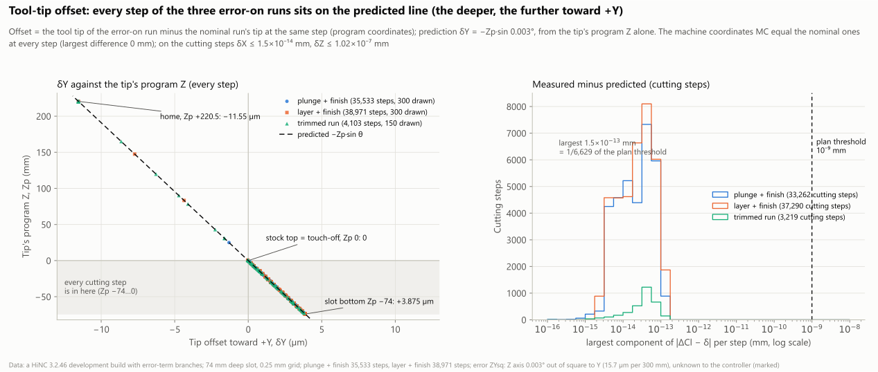
With the error terms on and the error marked: the tool-tip offset of every step (its CL minus the nominal run's, in program coordinates) against the tip's program Z. The plunge + finishing, layer + finishing and trimmed runs all lie on the predicted line δY = −Zp·sin 0.003°: 0 at the stock top (the touch-off point), +3.875 µm at the slot bottom Zp −74, −11.55 µm at machine home Zp +220.5. Right, the largest component of measured minus predicted per step on a log axis: at most 1.5 × 10⁻¹³ mm, against the plan's threshold of 10⁻⁹ mm. The machine coordinates equal the nominal run's at every step. 0.25 mm; a HiNC 3.2.46 development build with error-term branches.
- The offset depends on depth alone, not on X or Y. The error sits on the tool side, upstream of Z, and the table moves in X and Y underneath it, so each step's offset depends only on how deep the tip is below the stock top.
- Zero at the stock top, more the farther from the touch-off point. The pivot sits where the stock-top centre stands at the touch-off pose (dilemma 2). Retracted to Zp +200, the tip is off by 10.47 µm toward −Y (predicted); at machine home by 11.545 µm (measured). Neither place touches the stock.
IsToucheddiffers from the nominal run on 3 steps of one run. That is the plunge route's on run, on lines 21, 28 and 35 offinish.nc. These lines descend from one level to the next at X64 Y0, with the nominal tip at Zp −18.5, −37 and −55.5, inside the first plunged hole with zero radial clearance. The on run counts them as touching, the nominal run does not. Their tip and machine coordinates follow the prediction. The trimmed runs and the layer route have no such step.
The two long walls: shifted toward +Y together, plunged or layered alike
How it was measured: every vertex of the on run's exported cut was given its signed distance d to the same route's nominal cut. Positive = material left (Diff blue), negative = cut too deep (Diff red). The plunge route's mesh has 468,942 vertices, the layer route's 468,759. The wall box is x −62…62, |y| 6.2…6.4, which keeps clear of the R6.3 ends and of the floor's corners.
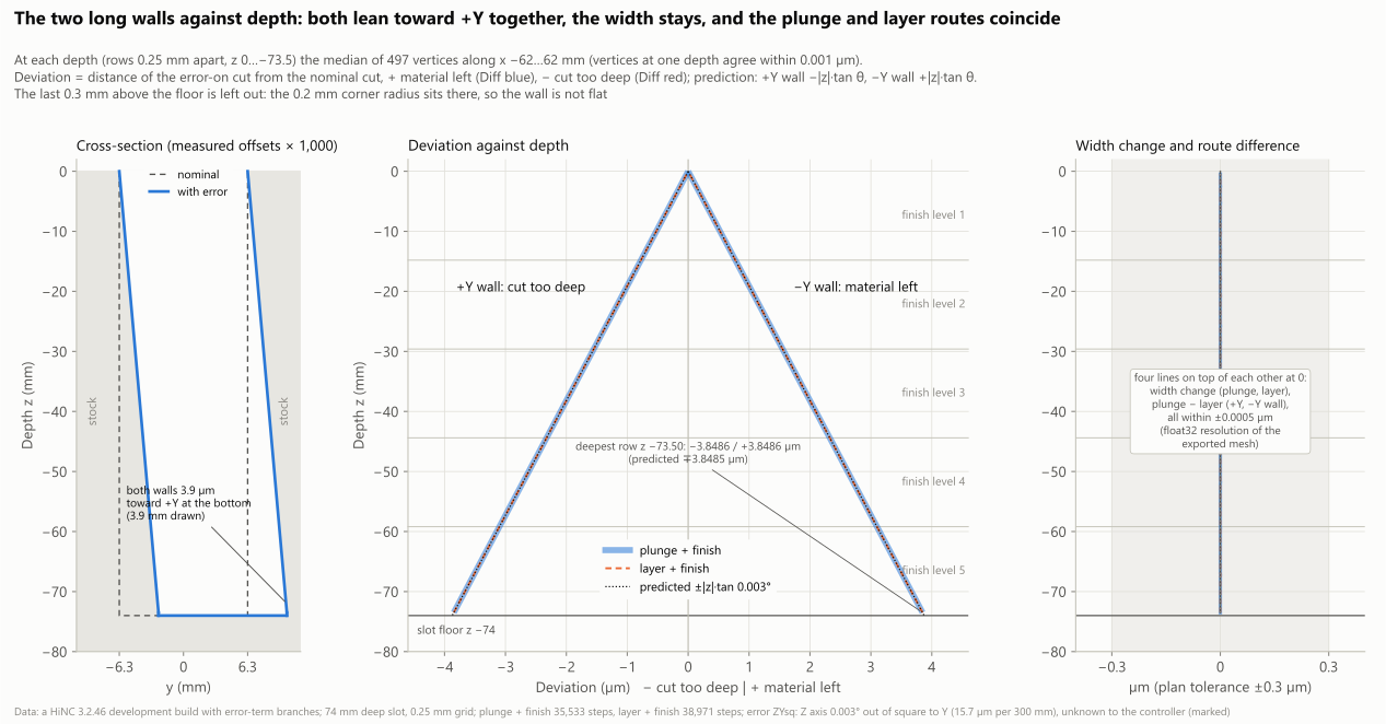
The deviation of the two long walls against depth, with the error terms on and the error marked (the median of 497 vertices at each depth). Middle: the +Y wall is cut too deep and the −Y wall keeps material, both along the predicted lines ±|z|·tan 0.003°, from 0 at the rim to ±3.849 µm at z −73.5. The plunge + finishing and layer + finishing lines coincide, and there is no step between the five finishing levels. Left: a cross-section drawn from the measured offsets enlarged 1,000 times; both walls lean toward +Y together. Right: the change of width and the difference between the two routes, both within ±0.0005 µm, against the plan's tolerance of ±0.3 µm. The deviation axis is symmetric. 0.25 mm; a HiNC 3.2.46 development build with error-term branches. This is the case's main evidence.
- Slope. Fitted against z, the +Y wall gives +0.05236 µm/mm and the −Y wall −0.05236 µm/mm, against 0.05236 µm/mm predicted (tan 0.003°); the intercept is −0.00001 µm. The walls agree with the prediction within 0.0005 µm, which is the smallest spacing of the exported mesh's float32 coordinates at y 6.3 mm.
- No trend along x. Split into four stretches along x (−62…62), the stretches' means differ by only 0.00002 µm.
- No step between the levels. The four boundaries between the finishing levels lie at z −14.8, −29.6, −44.4 and −59.2. Taking 1 mm above and 1 mm below each, the medians of the residual differ by ≤ 0.0001 µm.
- The width does not change. The two walls' deviations added at the same (x, z): median 0.000 µm, at most 0.0005 µm (predicted −1.6 × 10⁻⁵ µm).
- The plan's two boxes. z −73.7…−70 reads ∓3.757 µm (predicted ∓3.757), z −5…−1 reads ∓0.157 µm (predicted ∓0.157).
- The deepest row. At z −73.75 the +Y wall reads −3.8615 µm, exactly the prediction; the −Y wall reads +3.724 µm, 0.14 µm short. The analysis's reading: on the −Y wall this row of vertices lies inside the nominal slot, and the small facet of the nominal floor's corner (the 0.2 mm corner radius on the 0.25 mm grid) lies right below it, nearer than the wall, so the distance finds that facet (dilemma 7).
The wall bands of the five finishing levels (µm)
Each cell gives “+Y wall / −Y wall”. “Predicted (band mean)” assumes the vertices spread evenly in z; they sit only on the 0.25 mm grid rows, and the prediction computed over those same vertices is the measured value in the columns beside it. Every band agrees with the prediction within 0.0005 µm.
| Band | z range | Vertices (per wall) | Predicted (band mean) | Predicted (at the vertices) | Plunge route | Layer route |
|---|---|---|---|---|---|---|
| L1 | −0.3…−14.8 | 28,826 | ∓0.395 | ∓0.399 | −0.399 / +0.399 | −0.399 / +0.399 |
| L2 | −14.8…−29.6 | 29,323 | ∓1.162 | ∓1.165 | −1.165 / +1.165 | −1.165 / +1.165 |
| L3 | −29.6…−44.4 | 29,323 | ∓1.937 | ∓1.937 | −1.937 / +1.937 | −1.937 / +1.937 |
| L4 | −44.4…−59.2 | 29,323 | ∓2.712 | ∓2.710 | −2.710 / +2.710 | −2.710 / +2.710 |
| L5 | −59.2…−73.7 | 28,826 | ∓3.479 | ∓3.475 | −3.475 / +3.475 | −3.475 / +3.475 |
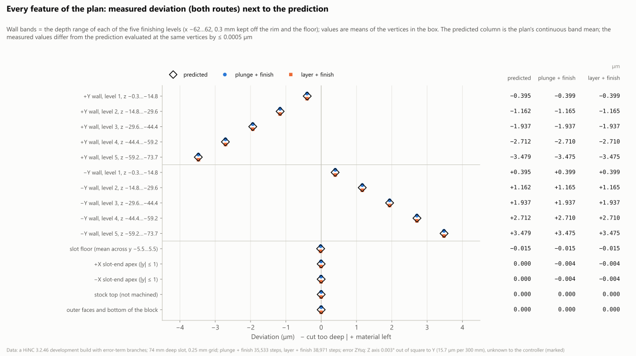
Every feature box of the design, with the error terms on and the error marked: one band per finishing level on each long wall, the floor, the two end apexes, the stock top and the outer faces. The prediction (open diamond), the plunge route (blue dot) and the layer route (orange square) coincide; the values are listed at the right. The wall bands' predictions, ∓0.395…∓3.479 µm, are band means; the measured ∓0.399…∓3.475 µm are the means over the vertices on the 0.25 mm grid rows. The horizontal axis is symmetric, ±4.5 µm. 0.25 mm; a HiNC 3.2.46 development build with error-term branches.
The floor and the slot ends
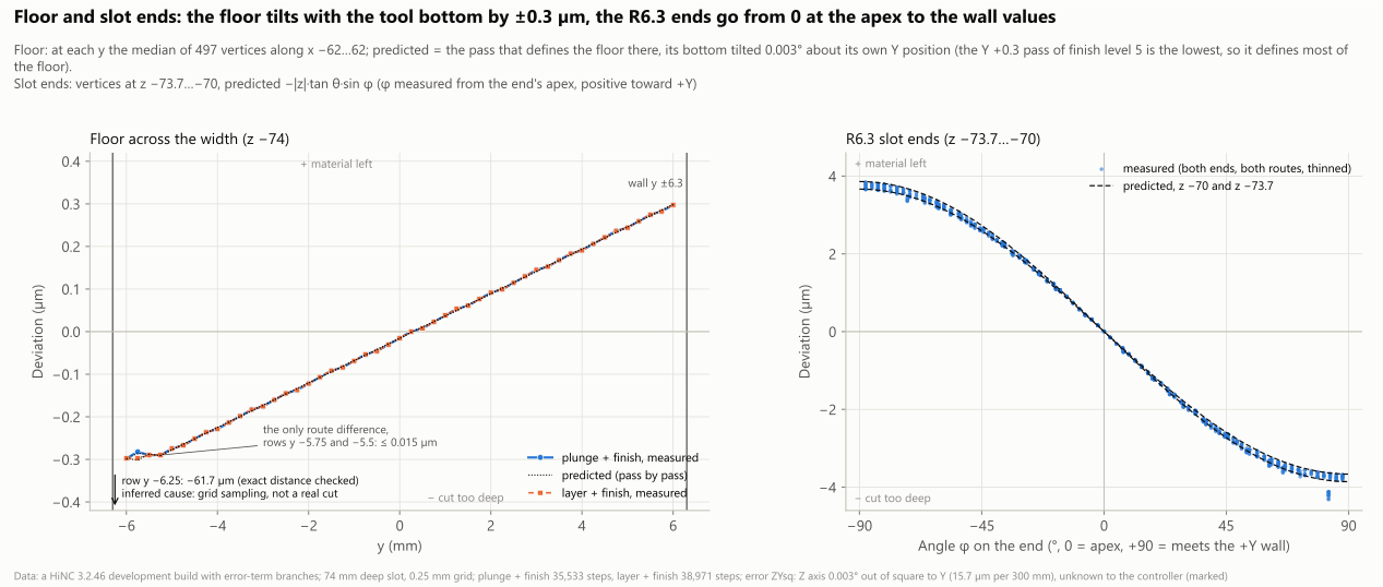
Left: the floor's deviation from the −Y edge to the +Y edge (the median of 497 vertices at each y). From −0.30 µm at the −Y edge to +0.30 µm at the +Y edge, tilted with each pass's tool bottom, within 0.01 µm of the pass-by-pass prediction. The two routes differ only in the rows y −5.75 and −5.5, by at most 0.0153 µm; there the roughing defines the floor, plunging one hole at a time and layering in one pass. The row y −6.25 reads −61.7 µm: checked with exact point-to-triangle distances, the value stands; grid sampling is the inferred cause, not a real cut (dilemma 7). Right: the R6.3 slot ends at z −73.7…−70, against the angle φ: from +3.8 µm where the end meets the −Y wall, through 0 at the apex, to −3.8 µm where it meets the +Y wall, along the prediction −|z|·tan θ·sin φ. The vertical axes are symmetric. 0.25 mm; a HiNC 3.2.46 development build with error-term branches.
- The floor tilts from one side to the other. The median at each y (497 vertices) runs from −0.298 µm at y −6 to +0.298 µm at y +6, a slope of 0.0523 µm/mm (predicted 0.05236). The floor box (y −5.5…5.5) has a mean of −0.015 µm, predicted −0.015 µm.
- Each pass's bottom tilts on its own. The floor is not one plane turned about one line: each pass's tool bottom tilts about that pass's own Y position (dilemma 6). Most of the floor is defined by the fifth finishing level's pass at Y +0.3, so y = 0 reads −0.0153 µm, not 0. This pass-by-pass model agrees with the measurement within 0.01 µm; the float32 spacing near the floor is 0.0076 µm.
- Where the two routes differ on the floor. The rows y −5.75 and −5.5 are defined by the roughing: plunging leaves one disc after another, layering the twentieth layer's single pass. The two differ by at most 0.0153 µm.
- The R6.3 ends. The deviation is −|z|·tan θ·sin φ, with φ measured from the end's apex, positive toward +Y: 0 at the apex, the +Y wall's value where the end meets the +Y wall and the −Y wall's where it meets the −Y wall. Over the 59,192 end vertices, measured minus predicted has a median of −0.009 µm, and 1–99 % of it lies within −0.13…+0.01 µm. Both apex boxes have a mean of −0.004 µm.
- The stock top and the block's outer faces: 0 (5,988 vertices on the stock top, 65,029 on the outer faces and the bottom).
The whole cut, by vertex distance
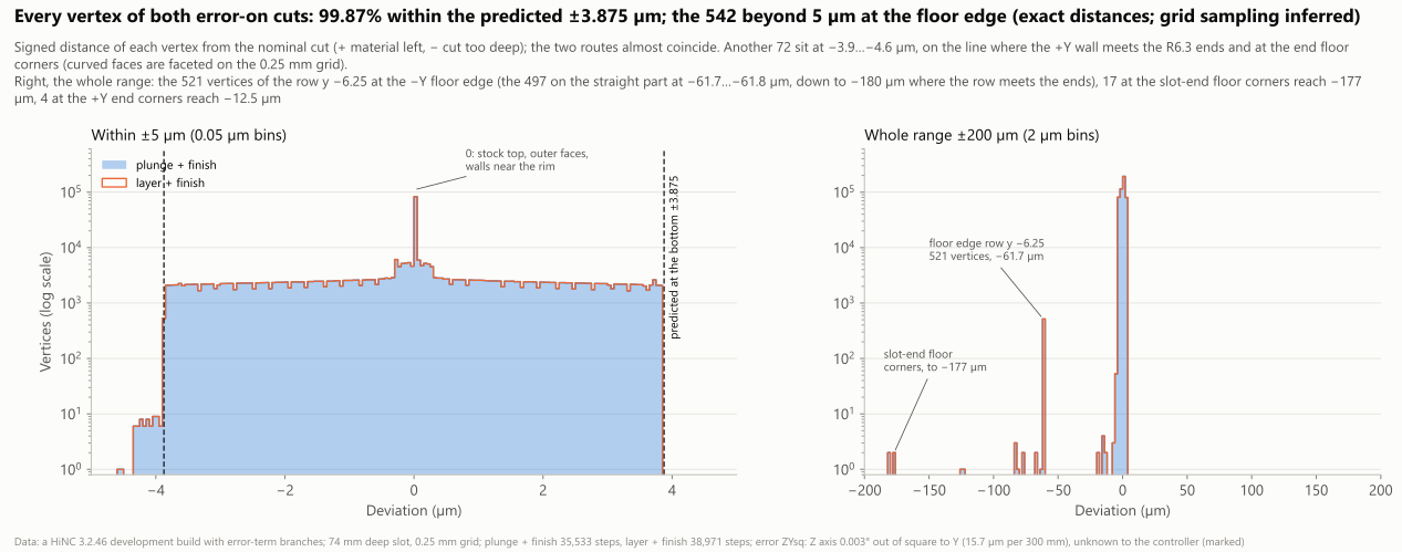
The distance of every vertex of the two on cuts from the same route's nominal cut (vertex counts on a log axis), in a ±5 µm and a ±200 µm panel. 99.87 % lie within the predicted ±3.875 µm; 72 lie at −3.9…−4.6 µm, on the line where the +Y wall meets the ends and in the ends' floor corners. The 542 beyond 5 µm all lie on the floor's edge: the 521 of the row y −6.25 at −61.7 µm (down to −180 µm near the ends), 17 end floor corners down to −177 µm and 4 +Y end corners down to −12.5 µm. All of these were checked with exact point-to-triangle distances, which equal the search values; the cause is inferred (dilemma 7). The two routes' distributions almost coincide. The horizontal axis is symmetric. A HiNC 3.2.46 development build with error-term branches.
Overall. The plunge route has 468,942 vertices, with a median of 0, a 1st percentile of −3.770 µm and a 99th of +3.737 µm (the layer route's 99th is +3.741); 99.87 % lie within the predicted largest deviation, ±3.875 µm.
72 vertices at −3.88…−4.60 µm. 64 lie on the line where the +Y long wall meets the R6.3 ends (|x| 64.81, y 6.25, z −66…−73.75), the rest in the ends' floor corners. On the 0.25 mm grid the R6.3 arc is faceted, a 0.25 mm chord having a sagitta of about 1.2 µm, and a vertex sliding along the face picks up part of it (the analysis's reading).
542 vertices (0.12 %) beyond 5 µm, down to −180 µm, all on the floor's edge: z −74 and the corner radius within 0.15 mm above it (dilemma 7).
- 521 in the row y −6.25 on the −Y side (z −74): the 497 of the straight stretch (|x| ≤ 62) all about −61.7 µm (−61.71…−61.81), and down to −180 µm near the ends;
- 17 in the ends' floor corners (z −74), at −6.1…−177 µm;
- 4 in the +Y end corners (|x| 64.5–64.75, y 6.25, z −73.85…−73.91, on the corner radius), at −5.0…−12.5 µm.
Both routes have the same vertices at the same values, and none is in any feature box.
These numbers came first from the distance search, which looks only at the 12 nearest triangle centroids and can overstate a distance next to large triangles, so all 542 were computed again as exact point-to-triangle distances. All 542 are real differences between the two meshes: the exact values differ from the search values by less than 10⁻⁵ µm. Their cause is still an inference (dilemma 7).
The two routes, vertex by vertex
| Plunge route | Layer route | |
|---|---|---|
| Vertices | 468,942 | 468,759 |
| Vertices the same in position and distance, bit for bit | 468,295 | 468,295 |
| Vertices differing by at most 1.53 × 10⁻⁵ mm in position and 0.0153 µm in distance (the floor rows y −5.75 and −5.5, z −74.0003) | 464 | 464 |
| Vertices only the plunge mesh has (on the stock top, at a distance of 0) | 183 | — |
- The ten wall bands' medians differ by 0.000 µm.
- The on runs' Diff captures: the two oblique views are the same pixel for pixel; the top view differs on 498 pixels, each by one colour level.
- Why they are the same. The finishing takes 0.3 mm off each wall, which removes everything the two roughings left on the walls, so the walls are defined by the finishing alone. And every pass, roughing or finishing, shifts by the same amount at the same depth. So whatever shape the roughing left, the finished walls are the same. That is what the plan predicted before the first play.
The Diff in the oblique view along the slot, alternating in place at one camera between the on runs of the two routes: plunge roughing then finishing, and layer roughing then finishing. The two captures are the same pixel for pixel; only the label changes. Change the roughing strategy, and the deep slot leans exactly the same way. This is the case's closing picture. Diff colour scale ±0.004 mm (red = cut too deep, blue = material left, green = 0, both signs weighted alike); 0.25 mm; a HiNC 3.2.46 development build with error-term branches.
The trimmed runs
The trimmed runs played the list “Trimmed PM”: the first five full-depth plunges of trim-pm.nc
(x 64 to 45.04), then one finishing loop down to −14.8 from trim-finish.nc; 4,103 steps a run, 3,219
of them cutting.
- The tool tip: the residual 1.51 × 10⁻¹³ mm, δY at Zp −74 3.874631 µm, the machine coordinates the same step by step, all as in the full runs.
- The row of holes (x 45.5–64, z −73.7…−15.3): the +Y side averages −2.36 µm (predicted −2.27) and the −Y side +2.17 µm (predicted +2.26), both with the predicted sign. The deepest band reads −3.46 / +3.37 µm, against a per-vertex prediction of −3.38 / +3.38 and the design's range of 3.3–3.9. The box at the first hole's +X apex (2,767 vertices) has a median of 0; its mean of +0.05 µm comes entirely from one vertex at (70, 0, −14.8) reading +136 µm (exact distance checked), and is −0.0002 µm without it.
- The walls of the finishing loop (z −0.3…−14.8): ∓0.386 µm (predicted ∓0.382).
- Vertices beyond 5 µm. The distance search read 167, 158 negative and 9 positive. All were
computed again as exact point-to-triangle distances: 163 (0.09 %) are really beyond 5 µm, 158
negative and 5 positive.
- The negative ones lie on the floor's edge and on the holes' y −6.0 grid plane, the same kind as in the full runs.
- The five positive ones, +27–141 µm, are real differences between the two meshes: three on the finishing level's boundary at z −14.8 (x 46.75, 64 and 70), two at the holes' end x 64 (z −74 and −73.84). Their cause was not traced: the nominal mesh was not at hand in the analysis. The full runs have no such vertex.
- Four on the floor of hole 2 (x 60.25–60.5, y 2.25–2.5, z −74), which the search read as +0.25 and +0.5 mm, one and two cells exactly, are only +0.11 / +0.13 µm by exact distance: artefacts of the search.
Marked and unmarked
This case has no unmarked run. The three programs are plain three-axis programs, whose machine coordinates follow from the program and the work offset alone. Whether the controller knows this squareness or not, it computes the same machine coordinates, and the error is cut into the part either way (What a mark changes). An unmarked run's tool tip and cut would be the same as the on run's, bit for bit; that is an inference, and no run was played to check it.
A real three-axis controller has to take such an error out with its own squareness compensation; HiNC does not simulate that compensation here.
The control runs and the comparison pictures
The control run (switch off, with a Diff) is the nominal run played again: its tip, machine
coordinates and IsTouched equal the nominal run's at every step, its Diff--Stats have no NaN leaf,
and the plunge and layer routes' control runs have the same Diff--Stats word for word.
Each of the three pictures below alternates, in place and at one camera, between error terms on (marked) and off (control), 0.9 s a frame, written as RGB frames at full size.
- The pictures come from putting each run's recorded stock back on the canvas with its Diff, not from a replay.
- The long walls face ±Y inside a closed slot, so from the front or the back only the block's outer faces show; all three cameras look down into the slot (dilemma 5).
- The canvas shows no interface text, so the English and Chinese canvas captures are the same pixel for pixel; only the labels follow the language.
- The pictures are the plunge route's. The layer route's on and off captures are the same pixel for pixel, apart from 498 pixels of the on run's top view, each one colour level off.
- The oblique views show only the +Y wall (cut too deep, yellow to orange); the −Y wall (material left, blue) faces away from the camera. In all the captures, the only Diff blue on the part is a few scattered pixels on the end arcs in the top view: 11 in the on run's, 3 in the control run's. The −Y wall's evidence is in the charts above.
The Diff in the oblique view along the slot (looking down into it from above the −Y side), alternating in place between error terms on (marked) and off (control). With them on, the +Y wall in view turns from green at the rim to yellow and orange deeper down, cut 3.86 µm too deep at the bottom; the −Y wall faces away from the camera. With them off, everything is green. This is the case's on/off comparison picture. Diff colour scale ±0.004 mm (red = cut too deep, blue = material left, green = 0, both signs weighted alike); 0.25 mm; a HiNC 3.2.46 development build with error-term branches.
The whole block in its vise, seen obliquely from above the −Y side, alternating in place. With the error terms on, the +Y wall in view inside the slot turns yellow deeper down (cut too deep); the stock top, the block's end faces and its outer faces are green (0). With them off, everything is green. Scale, grid and build as above.
The slot from the top, alternating in place. The walls are vertical, so from straight above only the floor and the rim show. With the error terms on, the floor carries a slight tint from one side to the other, yellow-green on the −Y side and cyan-green on the +Y side: ±0.3 µm is about 7 % of the colour scale. The scattered dots on the end arcs appear in both runs; they are sampling noise of the vertical ends seen from straight above. With the error terms off, everything but those dots is green. Scale, grid and build as above.
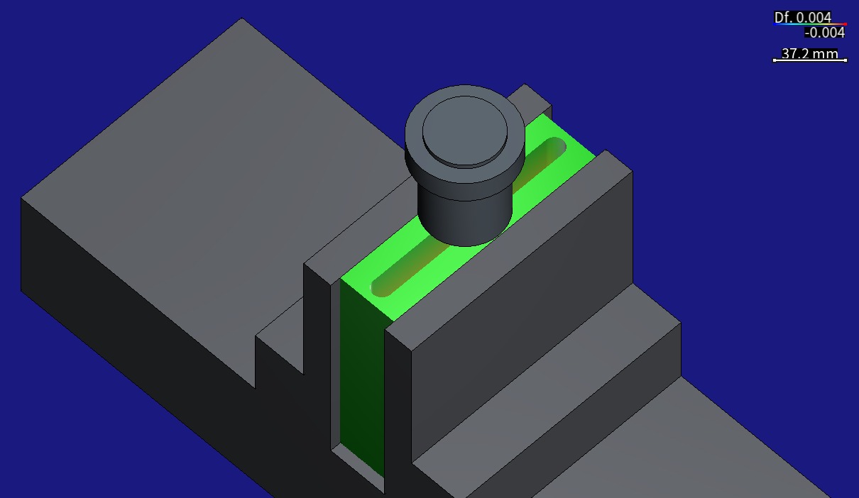
The holder in view, in a steeper oblique view from above: the same pose (pose-pm.nc, plunge 15 at
full depth), with the ER32 collet chuck and its nut above the slot's mouth and the cutter down in the
slot; the stock top and the slot's mouth are green. Scale, grid and build as above.
Diff--Stats of the six runs with a Diff
| Run | Reported leaves | Surface leaves before comparison | Expanded on demand | New nodes | NaN leaves | Measured wires | Unmeasured wires | Target triangles |
|---|---|---|---|---|---|---|---|---|
| t-control | 488,566 | 183,924 | 99,812 | 404,454 | 0 | 1,918,046 | 68 | 343,252 |
| t-on | 490,322 | 184,865 | 100,606 | 406,063 | 27 | 1,917,616 | 4,042 | 343,252 |
| f-pm-control | 665,036 | 468,440 | 67,152 | 263,748 | 0 | 2,628,544 | 84 | 915,104 |
| f-pm-on | 664,606 | 468,556 | 66,588 | 262,638 | 14 | 2,624,782 | 124 | 915,104 |
| f-tm-control | 665,036 | 468,440 | 67,152 | 263,748 | 0 | 2,628,544 | 84 | 915,104 |
| f-tm-on | 664,450 | 468,400 | 66,588 | 262,638 | 14 | 2,624,158 | 124 | 915,104 |
- The nominal runs make no Diff.
- The target triangle counts equal the triangle counts of the same STL read offline (915,104 and 343,252).
- The on runs have more NaN leaves (14 in the full runs, 0.002 % of the reported leaves; 27 in the trimmed one) and more unmeasured wires than the control runs; this was not followed up.
What the runs cost
All runs used private instances of a HiNC 3.2.46 development build with error-term branches on the shared 32-thread server, with physics off and collision detection on. The instance was restarted and the project loaded from its file before every run, so each VmHWM is that run's own peak.
| Play | List | Steps | Wall time | Per step | Peak memory (VmHWM) |
|---|---|---|---|---|---|
| t-nominal | trimmed | 4,103 | 205.4 s | 50.1 ms | 0.73 GB (0.68 GiB) |
| t-control | trimmed | 4,103 | 155.3 s | 37.9 ms | 1.16 GB (1.08 GiB) |
| t-on | trimmed | 4,103 | 260.7 s | 63.5 ms | 1.21 GB (1.13 GiB) |
| f-pm-nominal | plunge + finishing | 35,533 | 1,421.9 s | 40.0 ms | 1.52 GB (1.42 GiB) |
| f-pm-control | plunge + finishing | 35,533 | 986.0 s | 27.7 ms | 2.01 GB (1.87 GiB) |
| f-pm-on | plunge + finishing | 35,533 | 1,346.7 s | 37.9 ms | 2.25 GB (2.09 GiB) |
| f-tm-nominal | layer + finishing | 38,971 | 1,752.4 s | 45.0 ms | 1.69 GB (1.57 GiB) |
| f-tm-control | layer + finishing | 38,971 | 995.8 s | 25.6 ms | 2.11 GB (1.97 GiB) |
| f-tm-on | layer + finishing | 38,971 | 925.8 s | 23.8 ms | 2.37 GB (2.21 GiB) |
- Wall time runs from the start of the play to the poll that read
Finished, so it includes the export, the Diff and the stock record after the play. The status was polled every 5 s, so a wall time can be up to 5 s late. - In all, the six full runs took 7,428.6 s and the nine runs 8,050.0 s, about 2 hours 14 minutes. The times on 2026-10-06: build 21:22, trimmed runs 21:23:33–21:34:28, full runs 21:34:33–23:38:58.
- The server was not this case's alone. Runs of the same length took from 926 s to 1,752 s, and the fastest was f-tm-on, which also made a Diff: other cases were playing on the server at the same time, and the wall time follows that load more than the run.
- Against the design's estimate. The design estimated the trimmed runs on
trim-pm.ncalone, at most 1–2 minutes and about 1–1.3 GB each; the trimmed list also plays a finishing loop, and took 2.6–4.3 minutes and 0.73–1.21 GB. For the full runs it estimated 5–15 minutes and 1.5–2 GB each; they took 15.4–29.2 minutes, up to 1.95 times the upper estimate, and up to 19 % more memory (2.37 against 2 GB). - The memory of the Diff and the stock record. The two runs with a Diff peak 0.48–0.72 GB above the nominal run on the plunge route and 0.42–0.68 GB on the layer route. Not all of that is the Diff: the nominal run exports its cut and records no stock, the control run records its stock and makes the Diff but exports nothing, and the on run does all three.
- Units. VmHWM is converted from bytes: GB = bytes ÷ 10⁹, GiB = bytes ÷ 2³⁰.
- The pictures replay nothing. The recorded stock goes back on the canvas with its Diff; for the
two holder pictures, the pose program
pose-pm.ncis played on top.
What it means
For a machining engineer.
- A Z axis only 0.003° out of square with Y, 16 µm over 300 mm, puts a machine toward the upper end of the typical range. Such a machine leans both walls of a 74 mm deep slot toward +Y: the +Y wall about 3.9 µm too deep at the bottom and the −Y wall about 3.9 µm of material left, the width unchanged, and the slot's centre moving 0.052 µm toward +Y for every millimetre of depth.
- A machine's squareness is common to every pass. The plunged holes or the layers, and the five finishing levels, are all cut on the same tilted Z, and the finishing copies the lean as it is. Changing from plunging to layering, or back, does not remove it: either calibrate the machine or use the controller's squareness compensation.
- The wall's shape tells the cause apart: both walls leaning in parallel, one too deep and one with material left, and the width unchanged, is the fingerprint of the machine's squareness.
- The touch-off point is the zero of the deviation. Here the touch-off is on the stock top, which does not move; the deeper, the larger the deviation.
- In HiNC, a constant error measured on a machine can go into that machine's model, and its shape and size on your own part show before the part is cut.
For a teacher or a student.
- How a small angle upstream of Z becomes the tool-tip offset δ = (0, −Zp·sin θ, −Zp·(1 − cos θ)), and why it depends on depth alone and not on X or Y.
- Why a wall's offset depends only on its depth and not on which pass cut it, so that the roughing strategy and the number of finishing levels make no difference; and why the floor nevertheless shows each pass's own tilt.
- Pre-registering a prediction: “the two routes come out the same” was written before the first play and then tested with two plays.
- How a 0.25 mm voxel grid reads plane offsets of 0.4–3.9 µm to 0.0005 µm, and where it misreads: at the floor's edge and on the facets of a curved face.
For someone weighing the approach.
- Cost. The nine plays took 8,050 s of server time (the six full runs 7,428.6 s), at most 2.38 GB of memory each.
- Predictions, written before the first play: the per-step tip meets the formula within 1.51 × 10⁻¹³ mm; the walls' slope matches at 0.05236 µm/mm with residuals ≤ 0.0005 µm; the two routes' walls are the same, bit for bit.
- Misses and gaps, as measured: the floor is not one rigidly turned plane (the design's rigid turn holds only for passes at Yp = 0 and is a first-order approximation for the walls); 542 vertices at the floor's edge read −5 to −180 µm (checked with exact distances, grid sampling the inferred cause); the control runs have no cut of their own; two items of criterion 1 have no record.
Honest limits
- One error only, and a constant one. A real column also has a squareness of Z to X, straightness of the Z travel, positioning errors and thermal growth. An error term holds only a constant error (a squareness, the tilt of an axis, a rotary axis' location, a spindle's tilt, an offset of machine zero); errors that vary with position, backlash, servo mismatch and thermal deformation cannot be put in (Machine Geometric Error).
- The size and the direction are chosen. 0.003° is a typical squareness for a linear axis (the plan: toward the upper end of a 5–20 µm per 300 mm range), not a measurement of a HAAS VF2 or of any other machine; the paper measured no machine geometry. With the opposite direction, the +Y wall would keep material and the −Y wall be cut too deep, at the same size. The design mentioned an ISO acceptance tolerance; its original text was not checked, so it is not cited here.
- The Z tilt goes with the tool. The skeleton machine binds no spindle role, so a tilt of the spindle itself cannot be told apart from a tilt of the Z travel. The machine that would leave steps between the levels, “Z tilted, spindle square to the table”, cannot be modelled in this case (dilemma 1).
- Plain three-axis programs, so no unmarked run. How much a controller that knows the error could take back, this case cannot show.
- The touch-off is modelled by where the pivot sits. The pivot at the stock-top centre of the
touch-off pose stands for touching Z off on the stock top and finding the centre at that height.
Finding the Y centre 5–10 mm below the top would put another 0.26–0.52 µm into
G54Y (derived in the design) and shift the whole pattern by that much. With another touch-off point, the pivot has to be computed again. - Geometry only. Physics was off, so the removal geometry holds no tool deflection. This tool, at seven diameters of overhang, bends in the finishing itself, and a real part's walls are deflection and squareness together. The design's reading: deflection usually leaves material on both walls and narrows the slot, and it changes with the force and the strategy; a squareness leans both walls in parallel and leaves the width alone. Deflection was not simulated here.
- Reading the vertex distance.
- 542 vertices on the floor's edge read −5 to −180 µm. Checked with exact distances, the two meshes really are that far apart there; the −Y wall's deepest row reads 0.14 µm short (dilemma 7). The cause is inferred.
- The R6.3 ends are faceted on the 0.25 mm grid: on the line where the +Y wall meets the ends, 64 vertices read −3.89 to −4.33 µm, 0.43–0.47 µm more than the prediction at their depth, and 8 more in the ends' floor corners reach −4.60 µm. The 1st percentile of the ends' residual against the prediction is −0.13 µm.
- The distance search of the trimmed mesh read 9 positive vertices beyond 5 µm. Checked with exact distances: the four on hole 2's floor (searched at +0.25 / +0.5 mm) are only +0.11 / +0.13 µm, artefacts of the search; the other five, +27–141 µm, are real, three on the finishing level's boundary at z −14.8 and two at the holes' end x 64; their cause was not traced.
- The control runs have no cut of their own. Their noise floor is judged on four other pieces of evidence (criterion 4).
- The two routes' cuts were not measured mesh against mesh. The two on cuts were paired vertex by
vertex instead; that the two nominal cuts are the same is an inference (the same triangle count, the
same control
Diff--Stats). - The shape after the roughing was not measured. There is no export between the roughing and the finishing. The design predicted that the plunged holes' leaning walls and cusps and the layers' walls all lean by |z|·tan θ; this case did not check it.
- Two items of criterion 1 have no record: whether reopening the project with
ZYsqgave a load message, and whether the case's files outside the error-term folder stayed unchanged. - Observations not followed up. The plunge route's on run counts 3 steps as touching that the
nominal run does not, descents with zero radial clearance (see the tool tip); the on runs have more
NaN leaves and unmeasured wires than the control runs (see the
Diff--Stats). - The wall times include other load and were polled (see what the runs cost).
What a reader can take to their own case
- Put the error on a branch of its own, directly upstream of the axis it belongs to. Keep the axis' own motion, its values and its role as they were, and read the chain back after the build (Where an Error Term Goes).
- Put a static error's pivot where the tool tip stands at the touch-off. The deviation is then zero at the touch-off point, and the nominal work offset is the one a real touch-off would find. If the touch-off is made elsewhere, compute the pivot again, or type in the work offset the shop measured (Program Zero Alignment).
- Write the prediction down before the first play, an equivalence included. “The two routes come out the same” is a claim two plays can refute; written beforehand, it cannot be bent to the result.
- Check the tool tip first, against the formula. The per-step tip checks the model to 10⁻¹³ mm here, before any mesh is read.
- Make the same route's nominal cut the ideal geometry. Then the Diff shows the error, not the toolpath's own marks.
- Expect the angle times the depth. A Z squareness shows on deep walls, and the touch-off point is its zero: 0.003° is 3.9 µm at 74 mm.
- Read the signature before blaming the tool or the strategy. Both walls leaning in parallel, one too deep and one with material left, with the width unchanged, points to a machine's squareness; the design's reading is that a tool's deflection narrows the slot and changes with the strategy.
- Do not count on a roughing strategy to remove a machine's squareness. The finishing copies it; calibrate the machine or use the controller's squareness compensation.
- Read the floor pass by pass. Each pass's tool bottom tilts about that pass's own Y position, so a floor point ends at the lowest of the passes that swept it (dilemma 6).
- Chart a closed slot's walls against depth. The canvas shows such walls only at a grazing angle, and a camera looking down into the slot from one side sees one wall, not the other.
- Check extreme vertex distances with exact point-to-triangle distances, and read in boxes clear of the floor's edge and of faceted arcs. Here the floor's edge, where the nominal floor lies on a grid plane and the 0.2 mm corner radius is smaller than a cell, reads up to 180 µm off in both routes alike; the exact distances confirm that the two meshes differ there, and the cause is inferred (dilemma 7).
- Check a base mission before comparing two routes: the same resolution in every list, and no record entry that could read back another run's stock.
- Give the control run an exported cut of its own, so that the noise floor is measured the same way as the error.
- On a plain three-axis program a mark changes nothing in the cut: every error in the chain is cut into the part. A run with the mark cleared differs only under RTCP, a tilted plane or CL playback (What a mark changes).
Source and licence
The slot's geometry, the tool and the cutting conditions come from the article. The authors and the title, as the base case's source record gives them:
- Article: Francisco J. G. Silva, Rui P. Martinho, Luís L. Magalhães, Filipe Fernandes, Rita C. M.
Sales-Contini, Luís M. Durão, Rafaela C. B. Casais, Vitor F. C. Sousa, “A Comparative Study of
Different Milling Strategies on Productivity, Tool Wear, Surface Roughness, and Vibration”,
Journal of Manufacturing and Materials Processing 8(3), 115 (2024), MDPI, published 30 May 2024,
https://doi.org/10.3390/jmmp8030115. Search terms if the link moves:
A Comparative Study of Different Milling Strategies on Productivity, Tool Wear, Surface Roughness, and Vibration,jmmp8030115.
The article deposits no data and publishes no CAD model or NC program; every value the base case uses comes from its tables, figures and text. The article's machine is a HAAS VF2; this case does not model it.
Licence: Creative Commons Attribution 4.0 International (CC BY 4.0). The statement on page 1 of the article, which the Crossref record carries as well:
Copyright: © 2024 by the authors. Licensee MDPI, Basel, Switzerland. This article is an open access article distributed under the terms and conditions of the Creative Commons Attribution (CC BY) license (https://creativecommons.org/licenses/by/4.0/).
Attribution, as the base case's source record gives it:
Slot geometry, tool, cutting conditions and measured values after F. J. G. Silva, R. P. Martinho, L. L. Magalhães, F. Fernandes, R. C. M. Sales-Contini, L. M. Durão, R. C. B. Casais, V. F. C. Sousa, “A Comparative Study of Different Milling Strategies on Productivity, Tool Wear, Surface Roughness, and Vibration”, J. Manuf. Mater. Process. 2024, 8, 115, https://doi.org/10.3390/jmmp8030115, © 2024 by the authors, licensee MDPI. Licensed CC BY 4.0 (https://creativecommons.org/licenses/by/4.0/), provided as-is without warranties (CC BY 4.0 Section 5). No endorsement by the authors or MDPI is implied. Changes: nothing in the article; the block, the slot, the vise, the NC programs and the tool's unstated geometry were derived or chosen for this case (see What we changed).
What the base case changed (its “What we changed”): nothing in the article. The block, the slot's position, the vise, the three programs, the tool and its holder, the machine and the spindle were derived or chosen by the base case. For example, the article's Table 6 gives 30 plunges at a step of 4.8 mm, which cannot both hold in a closed 140 mm slot, so the plunge program has 28 plunges 4.741 mm apart; the finishing runs at the 213 m/min of the text.
What this page adds. One marked error-term branch on the machine, ZYsq. Its kind, its size
(0.003°), its direction and its pivot are the agent's choices; the article measured no machine
geometry, and the value is not a measurement of a HAAS VF2 or of any other machine. Nothing in the
article was changed. Through the base case, this page uses the article's slot geometry, tool and
cutting conditions only, not its measured times, vibration, wear or roughness.
The pictures and the charts. No figure or photograph of the article is reproduced. The pictures are HiNC captures, and the charts are drawn from HiNC's per-step results and cut meshes. Everything is simulated; nothing was cut. Neither the authors nor MDPI took part in this case or endorse it. This site offers no download; fetch the article from the publisher.
See Also
- Building Virtual Machine Tools: Error terms — where an error term may go, what a mark changes, the Enable Error Terms switch, and work offsets on a machine with error terms
- Kinematic Topology: Error-Term Branches — the nominal chain the controller solves, and which errors it can see
- Machining Issues Outside the Model: Machine Geometric Error — the machine errors the model leaves out
- Geometry Validation — the geometry difference, its detection radius and its colour scale
- Program Zero Alignment — P0, and typing in a measured work offset
- RPTU Benchmark Part 8 on a Machine with Three Measured Squareness Errors — three squareness errors on another three-axis skeleton machine, a squareness of Z to Y among them, read off an ISO 10791-7-style test piece
- A Roundness Test Part with the Machine's Measured Squareness Errors — a measured squareness of Z that leaves the roundness alone and leans the walls of three cylinders together
- Showcase — the other cases, and how a case page reads