A CubeSat side panel on a Z axis 0.2 mrad out of square with Y: milled flat, its end faces lean whole; drilled on edge, its holes lean while their mouths stay (3-axis)
- Original source
- The plate: Tim Munhowen (TU Wien Space Team), SpaceTeamSat1 Mechanical Design, Zenodo, version 1.0, 2025, doi:10.5281/zenodo.15482346, through the STS1 case. The error's size: Tormach 1100M factory inspection sheet TD10547 (revision 1023A), items G5a and G6a, a document the manufacturer publishes.
- Search keywords
SpaceTeamSat1 Mechanical Design,zenodo 15482346,CS_Yminus.STEP,Tormach 1100M certificate of inspection,TD10547- Licence
- The design is under CC BY 4.0, given as is, without warranty. The plate is the team's model, unchanged; the stock, the operations and clampings, the fixtures, the tools and holders, the programs and the machine are the agent's, from the base case, and the error is this case's. The error's size is a limit printed on the inspection sheet, not a measurement of any machine. Every picture here is a HiNC capture or a chart drawn from HiNC's results; the drawings are not reproduced.
- Attribution
- SpaceTeamSat1 mechanical design by Tim Munhowen, TU Wien Space Team (Zenodo,
doi:10.5281/zenodo.15482346), CC BY 4.0. Machining set-up by Tech Coordinate's agent.
Tech Coordinate's agent added one error-term branch to the simulated machine and chose its kind, its size, its direction and its pivots. Neither the author, the TU Wien Space Team nor Tormach endorses Tech Coordinate, HiNC or this case. - About the case
- The STS1 case built the TU Wien Space Team's 1U CubeSat structure, six Al 7075 plates, into HiNC: an AI agent wrote its own 2.5-axis CAM, 24 clampings and their Fanuc programs, each clamping played on the stock the one before it left. This case takes the side panel CS_Yminus, 91.4 × 94.0 × 14.9 mm, in three of its five clampings: OP1, the stock flat in the vise, the top half milled and drilled by eleven stage programs, from a D16 end mill down to a D1.6 drill; and E2 and E3, the plate standing on edge, M2, M3 and M4 holes, a D5.5 H7 seat and a D4 counterbore drilled into its two end faces. The machine is HiNC's three-axis skeleton: the table carries X and Y, the head Z. Here it gets one constant geometric error: its Z travel out of square with the table along Y by 0.2 mrad, 0.04 mm per 200 mm.
The story
A light milling machine's factory inspection sheet allows the spindle head's Z travel to stand 0.04 mm per 200 mm out of square with the table along Y. That is 0.2 mrad: a machine just at the edge of its acceptance, not a typical one. An AI agent put exactly that error into the STS1 case's three-axis machine and looked at one side panel of the CubeSat in the clampings that read it two different ways.
The error sits on a branch of the machine marked as an error term, directly upstream of the Z axis, so the head, the spindle and the tool lean together, and the tool tip moves 0.2 µm toward +Y for every millimetre it goes down. The pivot is where the tool tip stands at the touch-off: the centre of the stock top when the plate lies flat, the end face when it stands on edge, one machine file for each. There the deviation is 0, and each project's own G54 is the one a real touch-off would find. The controller solves its axes as if the branch were not there, while the simulated machine moves and cuts with it whenever the project's Enable Error Terms switch is on. The agent changed no line of the programs.
Before the first play, the agent wrote down the tool-tip offset it expected, the deviation of 25 feature boxes and ten pass criteria. Milled flat, every face toward ±Y would shift and lean, the −Y end face cut too deep and the +Y one with material left, more toward the bottom. Drilled on edge, the holes would lean toward the part's +z by 0.2 µm per millimetre of depth while their mouths stayed on the touch-off face. The real value leaves at most about 3.2 µm on the part, so each clamping also played at ten times the error, 2 mrad, as a display value. Each was played at 0.125 mm, geometry only:
- error terms off: the nominal cut, which every comparison of that clamping is measured against;
- off again, with HiNC's geometry difference (Diff) against the nominal cut: the noise floor;
- on, with the error marked, so the controller does not know it, at 0.2 and at 2 mrad.
The programs are plain three-axis work: G54, G43 and drilling cycles, with no RTCP, tilted plane or CL. Their machine coordinates come from the program and its offsets alone, and one trimmed run with the mark cleared, the controller knowing the error, cut exactly what the run with the mark cut.
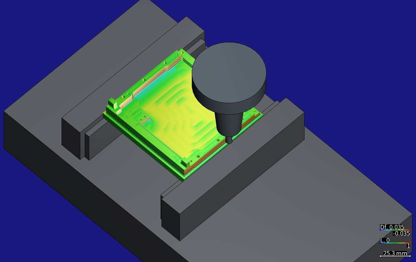
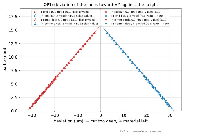
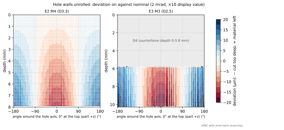

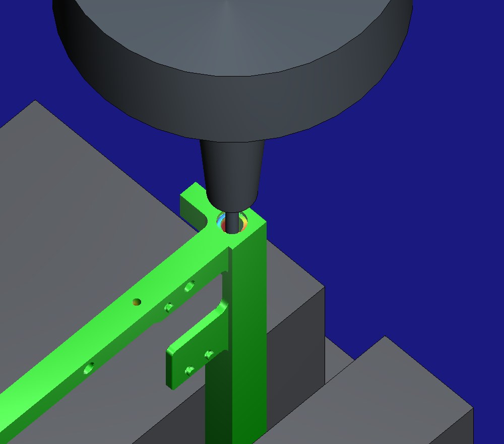
HiNC rendered these pictures from the plate, the vise, the tools and the programs of the base case; no drawing of the team is reproduced. The colours are HiNC's geometry difference (Df in the colour bar) against the cut of the same clamping's nominal run, on a symmetric scale: red = cut too deep, blue = material left, green = 0; ±0.035 mm on the plate milled flat and ±0.005 mm on the plate on edge, at ten times the error. The pictures were taken with the recorded stock and its Diff put back on the canvas, not from a replay; for the two holder pictures, a pose program brought the tool into view. The charts are drawn from the meshes of the cuts HiNC exported. Grid 0.125 mm.
| Key number | What it is |
|---|---|
| 0.2 mrad | the error: the Z travel out of square with the table along Y by 0.04 mm per 200 mm, the limit a light milling machine's factory inspection sheet allows, not a measurement of any machine. The tool tip moves 0.2 µm toward +Y per millimetre of depth, from 0 at the touch-off. Every number is also given at ten times the error, 2 mrad, the display value |
| 2.54×10⁻¹³ mm | the largest gap, over every step of the six runs with the error, between the measured tool-tip offset and the formula written before the first play, δ = (0, −Z·sin θ, −Z·(1 − cos θ)) with Z the tip's program Z: effectively zero. The machine coordinates equal the nominal run's at every step |
| ∓2.03 / ∓2.77 µm | the end bars' end faces of the plate milled flat, upper and lower band at the real value: the −Y face cut too deep and the +Y face with material left, as predicted to the hundredth of a micrometre; at ten times the error ∓20.31 and ∓27.69 µm. The end bars' inner faces read the other way round, ±2.39 µm |
| 2.000 µm per mm | the lean of the M3 hole's axis at ten times the error, 0.0019998 against sin θ = 0.002 (the M4: 0.0019945), extrapolating to only −0.10 to +0.13 µm at the end face, against 15 to 20 µm at the deepest slice: the mouth stays, the hole leans |
| −0.588 µm | the corner-block tops, cut last by a D6 at one height: an almost even overcut from the tool's tilted bottom, its radius times the angle (predicted −0.59). The rail's side facing −X reads 0 |
| 9.925–10.169 | the ratio of the deviation at 2 mrad to the deviation at 0.2 mrad in the 20 boxes that read at both: the part's response is linear in the error, so either set gives each feature's sensitivity |
| 55 min | server time for the 18 plays at 0.125 mm on the shared 32-thread server, 3,288.2 s: the plate on edge 4,535 or 5,251 steps and 5–30 s a play; the plate milled flat about 314,000 steps and 666–741 s, at up to 5.75 GB of memory |
Four of its nine dilemmas
A stock record that carried broken corner blocks
The plate's five clampings hand the stock on, each reading the record the one before it wrote, so the clamping that drills the −Y end face read the record of E1, a clamping the base case places 120° about a diagonal. HiNC has a known defect there: such a clamping reads no force, and the exported part has open edges round what it cut. The first round of the edge runs inherited it: the boxes of the M3 hole and its counterbore held not one vertex, and the exported cuts had 6,289 and 9,052 open edges at the corner blocks. A trial from the record of the clamping before E1 brought them down to 726 and 1,272 and the M3 hole out whole. E1's own holes meet none of the measured ones, so the agent wrote the change into a dated section after the plan, before it played the edge runs again.
Two touch-off heights, two pivots, so that G54 stays
A real machine's touch-off takes the constant shift the error causes at the touch-off pose into the work offset; HiNC's program-zero measurement, made on the nominal machine, takes in nothing. This plate is touched off at two heights: on the stock top when it lies flat, on the end face when it stands. With one pivot, at least one clamping's program zero would move by the height difference times the angle, the runs would disagree on G54, and the Diff would charge the missing touch-off to the error. The agent gave each touch-off height its own pivot, where the tool tip stands at that touch-off, at the price of two machine files. The offset a fit finds at program zero is at most 8.44×10⁻¹⁴ mm, and every run used its project's G54 unchanged.
A few tenths of a micrometre on a 0.125 mm grid
At the real value the largest deviation on the part is about 3.2 µm, at the foot of the end faces, 15.9 mm below the touched-off stock top; the hole mouths and the floors move only a few tenths of a micrometre, against a grid cell of 125 µm. The agent played a second set at ten times the error, kept in folders of its own and named as the display value wherever it appears, and measured both. Twenty boxes read at both values, in a ratio of 9.925–10.169; one, the counterbore floor's upper side, reads 0.28 µm at the real value, below three times its noise floor, and is reported as below it, as the plan said. The real-value pictures, at a ten times finer colour scale, look the same as the display ones.
What a read-only review found before the plan
Before the plan was committed, four read-only agents read the design, each from one side: the kinematics, the tool's behaviour, the criteria and the feature predictions. The corner-block top had been predicted from the D16, which stops 0.15 mm short; the D6 cuts it last, leaving an almost even −0.59 µm that the design's range of −1.6 to 0 was too wide to check. The counterbore-floor box took in the hole walls, which lean several times more than the floor tilts, so even a correct cut would have failed; it became two boxes on the ring alone. A rail-top box ran over a step. And a missing stock record lets HiNC play from the raw stock with one message, so every run now checks the records it reads before it plays.
The full record has the other five: the first round's seat floor, which read +1.75 µm from 46 vertices on the same broken stock and −0.50 µm from 1,081 once the stock was whole; the flat floors of the edge clampings, which still export a few hundred open edges, so that HiNC's own Diff reports its ideal geometry as not closed; why the hole walls are measured on the exported meshes, since the canvas has no section view; a slice past the M3 hole's exit that first pulled its axis to 0.00116; and the one or two extra steps of the flat runs with the error, so that their steps were paired by program line.
The result
All 18 plays ran to the end, with no collision, no rapid move through stock and no travel alarm, and every stage program of every play touched the stock. Eight of the ten criteria written before the first play passed as written; the other two, the noise floor and the cost, are records.
With the controller unaware of the error, the tool tip of every step sat where the formula written before the first play put it, the largest gap 2.54×10⁻¹³ mm: 0 at the touch-off height, toward +Y below it, and 0.7 to 0.8 mm off at ten times the error at the tool-change height, in the air. The machine coordinates of every step equal the nominal run's.
Milled flat, every face toward ±Y shifts and leans: the end bars' end faces read ∓2.03 µm on their upper band and ∓2.77 µm on their lower band at the real value, the corner blocks' end faces lean from ∓0.63 µm at the top to ∓2.73 µm at the bottom, and every 0.5 mm of height lies on the predicted line. The end bars' inner faces read ±2.39 µm the other way round, the floors carry the tilt of the tool's bottom, and the faces toward ±X read 0. Drilled on edge, the hole axes lean by 0.2 µm per millimetre of depth, within 0.3 % of the angle, and extrapolate to a tenth of a micrometre at the end face; the mouth box of the M4 hole reads 0.158 of its deep stretch. The control runs cut the nominal part to about 10⁻¹⁰ mm.
The study models this one error only, constant, at a published limit rather than a measured value; with the tilt the other way, every sign flips. The plays are geometry only, with no cutting force or deflection, and the edge parts lack the side holes of E1, the clamping the runs had to leave out. Everything is simulated; no plate was cut.
What it brought
- For a machining engineer: a Z axis 0.2 mrad out of square with the table, the acceptance limit of a light milling machine, does different things to the same plate in different clampings. Milled flat, every face toward ±Y shifts and leans, the −Y end bar's end face cut 2.0–2.8 µm too deep and the +Y one with as much material left. Drilled on edge, the holes lean 0.2 µm per millimetre of depth while their mouths stay on the touch-off face. The touch-off point is the zero, and the signature tells the cause: faces toward ±Y leaning together by one angle, faces toward ±X untouched, holes leaning from a mouth that does not move. Seated on a leaning end face, the panel would tilt its far end 18.8 µm, 19 % of the half band of the 1U drawing's 100.0 ± 0.1 mm, an inference rather than a simulation, and an order of magnitude below the bending of the small finishing cutters the base case measured. In HiNC, a constant error measured on a machine can go into its model, which shows what it does to your own part, and how much, before anything is cut.
- For a teacher or a student: how a small angle upstream of the Z axis becomes the tool-tip offset δ = (0, −Z·sin θ, −Z·(1 − cos θ)), and why it depends on depth alone. Why the same error leans a milled face whole but leaves a hole's mouth in place: what decides it is where the touch-off is and which way the face or the hole runs against the Z travel. Why a flat-bottomed tool's floor tilts by its radius times the angle. And a plan written before the first play, with a dated section, written before the rerun, for the one change the runs forced.
- For someone deciding whether to use an agent with HiNC: the study went from the base case's programs to one machine error's effects on three clampings in 18 plays and 55 minutes of server time, the four plays of the plate milled flat taking 2,788.0 s. The predictions were written before the first play; the largest gaps were 2.54×10⁻¹³ mm on the tool tip, 0.11 µm on the end faces at ten times the error and 0.3 % on the holes' lean. Where a prediction was wrong before the plan, where a stock record was broken and the runs were played again, and where a reading sits below the noise floor, the record says so.
Read the full case record: the CubeSat side panel with the Z axis 0.2 mrad out of square
How the six plates, the 24 clampings and the agent's own CAM came about is told in the base case: SpaceTeamSat1 CubeSat structure.