RPTU part 8: three squareness errors measured on a vertical machining centre leave a fingerprint of at most 1.7 µm on an ISO 10791-7-style test piece (3-axis)
- Original sources
-
Part and program: M. Schmitz, J. Mertes, F. Schillinger, M. Wagner,
Benchmark Dataset of 10 Multi-Feature Models for Single-Setup 3-Axis Milling, Zenodo, 2025 —
zenodo.org/records/17035762,
DOI 10.5281/zenodo.17035762.
The record describes part 8 as the benchmark part of Mertes et al. (2024,
doi:10.1016/j.dte.2024.100024),
based on ISO 10791-7. The case uses the authors' model and program as published, not a drawing from
the standard.
The three squareness values: M. Holub, R. Jankovych, J. Vetiska, J. Sramek, P. Blecha, J. Smolik, P. Heinrich, Experimental Study of the Volumetric Error Effect on the Resulting Working Accuracy—Roundness, Applied Sciences 10(18), 6233 (2020), DOI 10.3390/app10186233. The case uses the LaserTRACER calibration LTc1 in Fig. 6 and the ballbar test in Table 8. - Search keywords
zenodo 17035762,Benchmark Dataset of 10 Multi-Feature Models for Single-Setup 3-Axis Milling,app10186233,Experimental Study of the Volumetric Error Effect on the Resulting Working Accuracy Roundness- Licence
- Both sources are under Creative Commons Attribution 4.0 International (CC BY 4.0) and come without warranty. From the paper, the case takes three values read from a bar chart, plus one ballbar value as a cross-check. This page reproduces no picture from the data set or the paper. Every picture is a HiNC capture.
- Attribution
-
Model, NC program and rendering: M. Schmitz, J. Mertes, F. Schillinger, M. Wagner, "Benchmark Dataset
of 10 Multi-Feature Models for Single-Setup 3-Axis Milling", part 8, https://doi.org/10.5281/zenodo.17035762,
licensed CC BY 4.0 (https://creativecommons.org/licenses/by/4.0/), provided without warranty. The
simulation set-up (stock, placement, machine, spindle, tool geometry, holder, material) was derived or
chosen by Tech Coordinate; the model and the NC program are unchanged.
Squareness values (LaserTRACER calibration LTc1, read from Fig. 6; X–Y ballbar value from Table 8): M. Holub, R. Jankovych, J. Vetiska, J. Sramek, P. Blecha, J. Smolik, P. Heinrich, "Experimental Study of the Volumetric Error Effect on the Resulting Working Accuracy—Roundness", Applied Sciences 10(18), 6233 (2020), https://doi.org/10.3390/app10186233. © 2020 by the authors, licensee MDPI, Basel, Switzerland. Licensed CC BY 4.0 (https://creativecommons.org/licenses/by/4.0/), provided as-is without warranties (CC BY 4.0 Section 5). Changes: three values read from a bar chart and rounded to 0.0001°; no figure reproduced.
Tech Coordinate's agent added three error-term branches to the simulated machine and chose where they sit, their signs and their pivots. The authors of neither source endorse Tech Coordinate, HiNC or this case. - About the case
- This is part 8 of the accepted RPTU single-setup 3-axis milling benchmark. It is the only one of the ten parts made after ISO 10791-7, the accuracy test piece for machining centres: a Ø54 boss, a 54 mm square turned 30°, a step whose front and left sides are set at 3°, and a 78 mm block. One Ø6 flat end mill cuts them from an 80 × 80 × 51 mm block. Here the case's generic three-axis machine (the table carries X and Y, the head Z) gets three constant errors. They are the squareness errors Holub et al. measured with a LaserTRACER on a three-axis vertical machining centre (a KOVOSVIT MAS MCV 754 QUICK) before compensation: about 24 µrad between X and Y, 33 µrad between Y and Z and 56 µrad between Z and X. The simulated machine is not the one they measured; it borrows only the three angles.
The story
The base case turned the published part 8 into an accepted HiNC project. An AI agent derived the program zero from the program's own motion, found that the stated 50 mm block had to be 51 mm, and gave the job a standard Ø6 end mill in a shrink-fit holder. It accepted the set-up with replays at 1 mm and 0.25 mm. That machine was built exactly to design.
Here an AI agent was asked to show what errors measured on a real machine do to an accepted case. It chose part 8, because ISO 10791-7 reads a machine's geometric errors off the metal with exactly such circles, diamonds, slopes and squares. The agent took the three squareness errors from Holub et al. Each went on a branch of its own, marked as an error term, directly upstream of one linear axis: X–Y in front of Y, Y–Z in front of Z and Z–X in front of X. The controller solves its axes as if the marked branches were not there. The simulated machine still moves and cuts with them whenever the project's Enable Error Terms switch is on, like a real machine whose controller has no compensation for them. The three pivots sit where the tool tip is when the operator touches off at program zero. So the case's own G54 is the one a real touch-off would find.
Before the first play, the agent wrote down the tool-tip offset it expected, the deviation of every face and six pass criteria. It changed no line of the program. Then it played the whole program three times on a coarse 1 mm grid and three times on the case's 0.25 mm acceptance grid, geometry only:
- error terms off: the nominal cut, which every comparison is measured against;
- off again, with HiNC's geometry difference (Diff) against the nominal cut: the noise floor;
- on, with the errors marked, so the controller does not know them.
The program is plain three-axis work: G54 and G43, with no RTCP, tilted plane or CL. Its machine coordinates come from the program and the work offset alone. So by the design's reasoning, a controller that knew the errors would cut the same part; no run was played to show it.
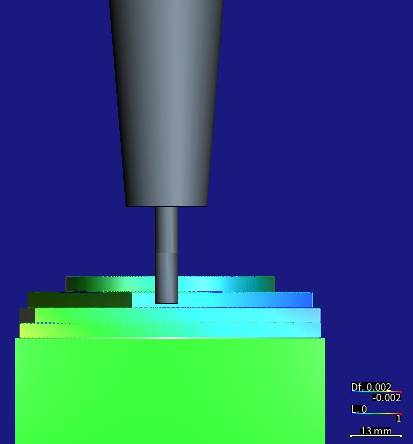

HiNC rendered these pictures from the CC BY 4.0 model and program of M. Schmitz, J. Mertes, F. Schillinger and M. Wagner, on the case's generic machine with the three errors the agent built in. The cut parts were put back on the canvas with their Diff, not replayed. For the first picture, a parking program brought the tool into view without cutting. The colours are HiNC's geometry difference (Df in the colour bar) against the part the nominal run cut, on a symmetric scale of ±0.002 mm: red = cut too deep, blue = material left, green = 0. The grid is 0.25 mm.
| Key number | What it is |
|---|---|
| 24 · 33 · 56 µrad | the three squareness errors, X–Y, Y–Z and Z–X. They were read from Holub et al.'s bar chart of a LaserTRACER calibration before compensation (to ±1–2 µrad) and typed in to 0.0001°: 24.43, 33.16 and 55.85 µrad. The paper prints no sign rule, so the agent read the signs by the right-hand rule |
| 1.4×10⁻¹³ mm | the largest gap, over all 159,337 cutting steps, between the measured tool-tip offset and the exact three-angle formula written before the first play. To first order the offset is (−ψZ, −θX − φZ, 0), where θ, φ and ψ are the X–Y, Y–Z and Z–X angles. It does not depend on Y, it is zero at program zero, where the touch-off is, and it reaches 0.95 µm in X and 2.01 µm in Y |
| −1.64 / +1.68 µm | the extremes on the walls (predicted −1.642 and +1.671 µm): cut too deep at the +X end of the block's back face, and material left at the +X end of the 3° face. 98 % of the cut's 190,615 mesh vertices lie between −1.14 and +1.48 µm |
| +24.39 / −24.45 µm/m | the slopes of the block's front and back faces along X: the X–Y angle, read off the part. The left and right faces slope by +55.99 and −56.01 µm/m with height, which gives the Z–X angle. All six angles read off the faces lie within 1 % of the values put in |
| +1.90 µm over 78 mm | how far the block's left face is turned against its front face (predicted +1.906): the front-left corner opens beyond 90° by the X–Y angle. The 30° square's corners change by only ±0.65–0.66 µm over 54 mm, half of it. The 3° face turns with the front (+0.002 µm) |
| 0.733 µm | the Ø54 boss's two-lobe roundness. Its centre moved (+0.17, −0.90) µm; with that taken out, the boss reads two lobes with the long axis at −45°/135°. The lobes follow the 30 mm radius of the cutter-centre path, not the boss's 27 mm |
| 0.003 µm | the largest median gap, over the fifteen wall boxes fixed before the play, between the measured deviation and the formula applied vertex by vertex after it. The floors match a sweep of the tilted flat end within 0.001 µm |
| 7.82 µm | what the same X–Y squareness makes on the 320 mm edge of an ISO 10791-7 test piece; across part 8's 80 mm it is nearly 2 µm |
| 405.6 s | server time for the six plays, 192,851 steps each. On the shared 32-thread server, each 0.25 mm play took 85–95 s and at most 1.69 GB of memory |
Four of its six dilemmas
Three angles on three axes
A squareness is the angle between two axes, and each of the three errors sits directly upstream of one axis, one error per axis. X–Y went in front of Y and Y–Z in front of Z: the second axis of each pair. ISO 230-1 writes Z–X (EB0Z) as an error of Z, but Z already carried Y–Z. So Z–X went in front of X: the X slide, with the Y slide, the table and the part on it, turns 55.85 µrad about +Y. Seen from the part, the Z travel and the tool tilt the other way. For the cut, that is the same as an opposite rotation in front of Z, the paper's EB0Z of about −56 µrad. The price is that the table and fixture on the canvas tilt 56 µrad too, too little to see. A wrong sign would have swapped material left and cut too deep on the left and right faces. The steps give the angle back as 55.8505 µrad, and the faces show the predicted signs: the left face is cut too deep and the right one left thick.
Pivots at the touch-off point
Where a static rotation turns decides how far it moves the whole part. On a real machine the operator touches off on the part, and the G54 found there absorbs whatever the errors shift at that pose. HiNC measures program zero on the nominal machine and absorbs nothing. With the pivots left at the machine's origin, the part would have shifted: +10.8 µm in Y from X–Y, −15.6 µm in Y from Y–Z and −26.3 µm in X from Z–X. A touch-off removes such shifts, but the comparison would have charged them to the errors. So the agent put all three pivots at the tool tip in the touch-off pose, with the tip at program zero. The deviation there is zero, and the case's G54 (−441, −291, −529) is what a touch-off would find; no work offset was typed. The fit over the steps leaves an offset of the order of 10⁻¹⁴ mm at program zero. Far from that point, the steps of the approach from machine zero (program X 441, Z 424 mm) are off by (−23.7, −24.8) µm, as the formula says.
Below 1 µm on a 0.25 mm grid
By the first-order formula, these three angles move the part's surface by about 1.7 µm at most. The Z tilt moves it by less than 1 µm and the floors by 0.2 µm, while a voxel of the 0.25 mm grid is 250 µm wide. The agent did not scale the errors up, which would have taken the numbers away from a real machine's. Instead it set the Diff scale to ±0.002 mm. Before the play it also wrote down a fallback: if the tool tip passed and the part did not, the report would call the grid too coarse below a micrometre, not the error model wrong. The grid reads them. On the block's four faces, 98 % of the grid nodes lie within −0.03 to +0.02 µm of the first-order prediction. On every wall box, the vertex-by-vertex gap to the prediction has a median within 0.003 µm, and the three angles come back off the part within 1 %.
A floor left high
The design expected the low edge of the tilted flat end to sweep every floor, so the floors would come out 0 to 0.19 µm deep. Instead, the 1 mm frame floor at Z−17 on the left read +0.06 to +0.12 µm of material left. The top view of the Diff also showed a faint cyan band on the Z−9 floor beside the 30° square. The tool axis tilts about 65 µrad with the Z travel, so the bottom of the Ø6 flat end sits up to 0.19 µm above its centre on one side and as much below on the other. The agent swept that tilted bottom along the run's own steps and kept the lowest pass at each floor point. The frame floor lies at X1–2, while the cutter centre runs outside the part at X−1, so only the raised +X side of the bottom reaches it. The sweep gives +0.087 µm against +0.088 µm measured, every vertex within 0.001 µm. As the sweep predicts, the band fades from +0.15 µm next to the wall to −0.18 µm 6–8 mm away.
The full record has the other two. One is why part 8 took the place of part 7, the starting point the designer agent was given. The other is three kinds of mesh-distance readings that are not the error, among them +176.8 µm beside convex edges, exactly 0.25 mm/√2.
The result
All six plays ran to the end, 192,851 steps each, with no collision and no travel-limit message.
With the errors on and the controller unaware of them, the tool tip of each of the 159,337 cutting steps sat where the exact formula written before the first play put it, within 1.4×10⁻¹³ mm. To first order, the tip moves −θX in Y as it travels in X (X–Y). As it goes down, it moves ψ|Z| in +X (Z–X) and φ|Z| in +Y (Y–Z). The offset does not depend on Y and is zero at program zero, the touch-off point. It reaches 0.95 µm in X at the deepest level, Z−17, and 2.01 µm in Y at the far end of the facing pass, X 83.8. Every step's machine coordinates are bit for bit the same as in the nominal run.
On the part, each face keeps only the part of that offset along its normal. The block's front face and the 3° face, both facing −Y, are left thicker toward +X: +1.33 and +1.50 µm at X74–76. The back face is cut deeper toward +X: −1.40 µm at X74–76. Front and back turn together, so the block keeps its width. The left faces are cut too deep and the right face is left thick, both changing with depth only. The right 8 mm wall goes from +0.53 µm at Z−9.5 to +0.92 µm at Z−16.5. The 30° square's front-right side is left thickest, +1.18 µm. The Ø54 boss's centre moves (+0.17, −0.90) µm, and two lobes come on top of that. The three boxes on the floors and the top face read only −0.195 to +0.116 µm. On each of the fifteen wall boxes fixed before the play, the gap between the measured deviation and the formula, taken vertex by vertex, has a median within 0.003 µm.
Read the way a CMM would read it, the piece shows the angles feature by feature. The block's left face is turned +1.90 µm over 78 mm against its front, so the front-left corner opens beyond 90° by the full X–Y angle. Each corner of the 30° square changes by only about ±0.66 µm over 54 mm, half of it. The 3° face turns with the front and keeps its angle. The boss's two lobes, with a two-lobe roundness of 0.733 µm and the long axis at −45°/135°, follow the 30 mm radius of the cutter-centre path, not the boss's own 27 mm. From the faces' slopes, the agent read the three angles back within 1 %. The front and back faces gave X–Y as 24.39 and 24.45 µrad, and their slopes with height gave Y–Z as 33.41 and 32.91 µrad. The left and right faces gave Z–X as 55.99 and 56.01 µrad.
The control run repeated the nominal run step for step, and its Diff stayed green, reading −0.034 to +0.036 µm by hue.
The study models these three constant errors only. The values were read from a bar chart, to ±1–2 µrad. With the opposite signs, material left and cut too deep would swap on every face, at the same size. The machine is the case's generic one, not the one Holub et al. measured. The plays are geometry only, with no cutting force or deflection. Everything is simulated; no part was cut.
What it brought
- For a machining engineer: a reasonably calibrated machine, with three squareness errors of 24–56 µrad, leaves at most about 1.7 µm on this 80 mm piece. The front is left thick and the back cut deeper, both more so toward +X. The left face is cut too deep and the right one left thick, and the 30° square's front-right side is left thickest, at +1.18 µm. A squareness prints as its angle times the travel a feature spans. The same X–Y error makes 7.82 µm on the 320 mm edge of an ISO 10791-7 test piece, while the two Z squarenesses take a deep part to show. The touch-off point is where the deviation is zero, and it grows with the distance from there. In HiNC, a constant error measured on a machine can go into its model. HiNC then shows what it does to your own part, and how much, before anything is cut.
- For a teacher or a student: why the ISO 10791-7 test piece carries a square, a square turned 30°, a circle and a 3° slope. One X–Y squareness opens the square's corner by the full angle and changes the turned square's corners by half of it. It turns the circle into two lobes on the −45°/135° diagonal and leaves the 3° slope's angle to the datum alone. The page also shows how the tip offset follows from the machine's chain, and why it does not depend on Y. It shows why the lobes follow the 30 mm radius of the cutter-centre path rather than the 27 mm boss. And it shows why a tool axis tilted 65 µrad moves a floor by only 0.2 µm, with the sign set by which side of the flat end sweeps it.
- For someone deciding whether to use an agent with HiNC: the study took six plays and 405.6 s of server time, at most 1.69 GB of memory a play. The formula and the design values were written before the first play. The tool tip matched the exact formula within 1.24×10⁻¹³ mm per component. The fourteen wall boxes with a design value lay within 0.13 µm of it in the median. Applied vertex by vertex after the plays, the same formula leaves a gap whose median is at most 0.003 µm on each wall box, and a gap of at most 0.009 µm on each of the 19 ISO-style indicators. The record also says where the design missed: a frame floor came out thick, and uneven vertex spacing drew the front and back medians toward zero.
Read the full case record: RPTU part 8 with three squareness errors
The accepted case this page builds on, with how part 8 was placed, its stock worked out and its tool chosen: RPTU single-setup 3-axis milling benchmark.