Jetson AGX Thor enclosure, bottom shell: with X and Y 0.003° out of square, the part turned over between its two set-ups comes out with their faces 8.85 µm apart at the ends of the long walls; seated in soft jaws machined on the machine, the mismatch turns to run along X and the wall seam is gone (3-axis)
- Original sources
-
The part: Antmicro, Enclosure for Antmicro baseboard with NVIDIA Jetson AGX Thor,
github.com/antmicro/jetson-agx-thor-baseboard-enclosure
(branch
main, read 2026-09-30); the bottom shell's STEP modelcnc-milled-bottom-shell-aland its drawing.
The size of the error, as a reference only: Holub, Jankovych, Vetiska, Sramek, Blecha, Smolik, Heinrich, Experimental Study of the Volumetric Error Effect on the Resulting Working Accuracy—Roundness, Applied Sciences 10(18), 6233 (2020), doi:10.3390/app10186233: one value read off the bar chart of its Fig. 6, the X–Y squareness of a three-axis vertical machining centre before compensation, 24.4 µrad. - Search keywords
antmicro jetson-agx-thor-baseboard-enclosure,cnc-milled-bottom-shell-al- Licence
- Apache License 2.0, given as is, without warranty. Antmicro's README: "Copyright (c) 2026 Antmicro" and, under Licensing, "This project is published under the Apache-2.0 license." The part is Antmicro's model, not changed in a single point. Every picture here is a HiNC capture, a chart drawn from HiNC's results or a schematic the agent drew; no third-party picture is reproduced, and of the paper only one number is used. The machine, the stock, the fixtures, the tools and the programs are the base case's; the error is the agent's choice, and its size and sign are not a measurement of any machine.
- Attribution
-
As the base case's source record gives it:
"Enclosure design (c) 2026 Antmicro, Apache-2.0,
https://github.com/antmicro/jetson-agx-thor-baseboard-enclosure. Machining set-up by Tech
Coordinate's agent (changes: stock, fixtures, toolpaths)." The NVIDIA product name is used only to say
what the enclosure fits.
For this case Tech Coordinate's agent added one error-term branch to the simulated machine, directly upstream of the Y axis (an X–Y squareness of 0.003°, a typical value it chose); the second set-up's stock, turned over from the part the first set-up cut, and for one run turned a further −2θ, an assumption about the fixturing; and a parking program that cuts nothing. The design geometry is unchanged. - About the case
- The accepted bottom shell of the Jetson AGX Thor enclosure: Antmicro's U-shaped aluminium shell, 169 × 111 × 40.5 mm, open at both ends, with 3.5 mm walls and a 2.0 mm floor, machined in two set-ups on a generic three-axis machine. OP10 machines the inside from a block held in a vice by a tab; OP20 turns the part over about X onto a plug made to the cavity, holds it in soft jaws and machines the outside. Here that machine gets one constant geometric error: X and Y are 0.003° out of square, 15.7 µm over 300 mm. That is a typical size the agent chose; nobody measured this generic machine.
The story
In the base case an AI agent wrote its own CAM for the four aluminium parts of Antmicro's open-hardware enclosure, two set-ups each, and accepted them in HiNC at a 0.25 mm grid. This case takes the bottom shell. OP10 holds a 175 × 117 × 49 mm block in a vice by an 8.5 mm tab and machines the inside in five programs, split at the tool changes: face and outer contour, the outer groove with a T-slot cutter, the cavity with its inner walls, bosses and pads, the corners, and a narrow slot between two bosses. OP20 turns the part over and, in one program, faces the tab off, finishes the outer contour down to Z−6, cuts the 49° chamfers along both long edges with a D6 ball end mill, drills 7 × Ø2.7, 4 × Ø3.3 and one Ø5.1 hole, and cuts seven countersinks with a D2 ball end mill. All are plain three-axis programs, G54, G43 and G81, with no RTCP and no tilted working plane.
Here the agent gave that machine one common geometric error: X and Y out of square by 0.003°, 52.36 µrad, the squareness between the X and Y motions of ISO 230-1. It lies in the upper middle of the 5–20 µm per 300 mm common for the squareness of linear axes; Holub and colleagues measured 24.4 µrad (0.0014°) with a laser tracker on a three-axis vertical machining centre before compensation, and this is about 2.1 times that. The Y slide, carrying the table, sits on the X slide turned by θ about Z. Seen from the part on the table, the Y travel still runs along the part's y, but the X travel runs at (cos θ, −sin θ): in each set-up the faces facing ±Y are sheared by −θx, ±4.4 µm at the ends of the long walls, x ±84.5.
In HiNC an axis or the spindle of the machine chain can be given an error term, a static branch of its own just before the axis's branch. On this machine X is below and Y above, so the branch directly upstream of the Y axis sits exactly between the two slides: a static rotation named XYsq on X → Yerr, marked as an error term, with the Y axis's translation moved unchanged to Yerr → Y. Upstream of X, the two slides and the table would turn together, and the tip would only shift by a constant that a touch-off takes in. The controller solves its axes as if the marked branch were not there, while the simulated machine moves and cuts with it whenever the project's Enable Error Terms switch is on, like a real machine whose controller does not know its squareness. The pivot lies on the spindle axis at the touch-off pose of both set-ups, G54 X −381 with the tip at program zero. A rotation about Z does not depend on height, so one pivot serves both set-ups: program zero does not move, and a touch-off finds the nominal G54. OP10's project already stores it; the OP20 base project stores zero there, so every OP20 run typed it in. No program line was changed.
The agent chose this error for the turn-over. OP20 turns the part about X, which flips y, so on the finished part the faces OP10 cut carry +θx and the faces OP20 cut −θx. Wherever a size or a step has one face from each set-up, the two faces stand 2θx apart, 8.85 µm at the wall ends, and on this part the long walls' two bands, the holes and their bosses, the holes and their pads are split exactly that way. Where the doubled mismatch lands depends on how OP20 locates the part, which the error term does not decide, so the agent played two ways:
- A, placed in the design frame, as the base case does, like a probed touch-off or an external fixture: the mismatch runs along y and grows with x;
- B, seated in soft jaws or on a plug machined on the same machine, the long walls along the X travel again: A's stock turned a further −2θ about OP20's program zero. B is an assumption about the fixturing, not an error-term feature.
Before the first play, the agent committed a plan with the tool-tip offset it expected, the deviation in 29 measuring boxes and twelve pass criteria. Seven trimmed plays at 1 mm checked the build, the typed work offset and the formula. Then the whole case played at 0.25 mm, the base case's acceptance grid, geometry only, in one job: OP10's five programs in one run, then OP20 on the part OP10 had cut, exported, turned over with the base case's own matrix and rebuilt as stock:
- error terms off: the nominal cut, which every comparison is measured against; OP10's nominal cut, turned over, is also the stock of OP20's nominal and control runs;
- off again, with HiNC's geometry difference (Diff) against the nominal cut: the noise floor;
- on, with the error marked, so the controller does not know it: OP20 starts from OP10's cut with the error, turned over (A), and once more from the same stock turned −2θ (B).
A trimmed run with the mark cleared, as a controller with calibrated kinematics would know the error, played OP10's first program.
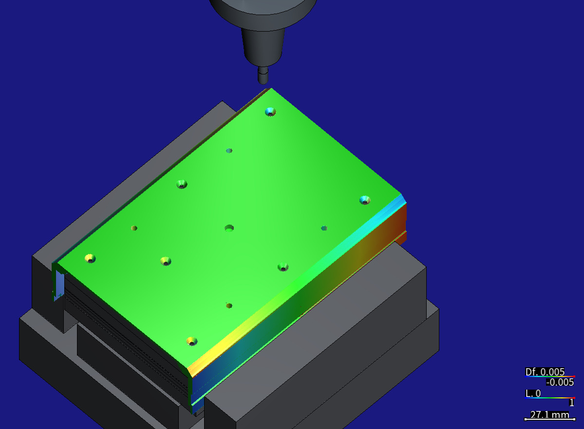
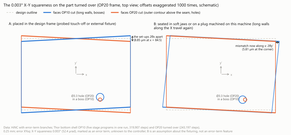
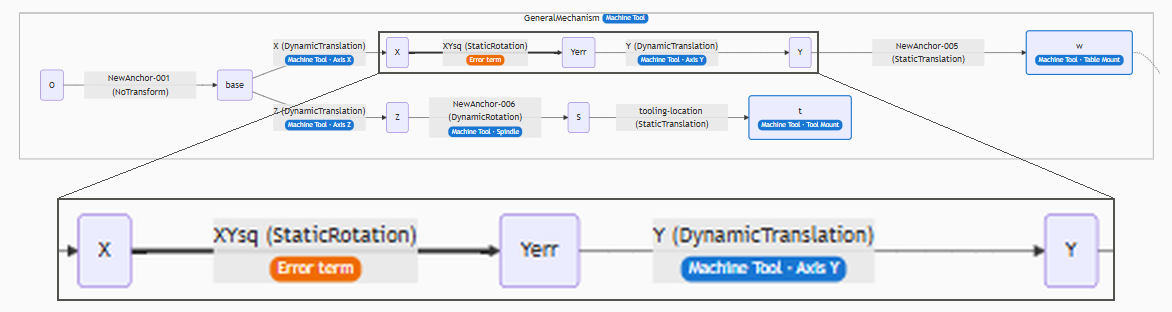
HiNC rendered these pictures from Antmicro's model (Apache-2.0) on the base case's machine with the error-term branch the agent built in, and with the base case's stock, fixtures, tools and programs. The cut parts were put back on the canvas with their Diff, not replayed; for the first picture, a parking program brought the tool into view without cutting. The colours are HiNC's geometry difference (Df in the colour bar) against the part the nominal run cut, on a symmetric scale of ±0.005 mm: red = cut too deep, blue = material left, green = 0. The grid is 0.25 mm. The charts are drawn from HiNC's step results and the exported cuts; the mechanism picture is a schematic.
| Key number | What it is |
|---|---|
| 0.003° · 15.7 µm / 300 mm | the error: X and Y out of square (ISO 230-1), put in as a static rotation θ directly upstream of the Y axis. A typical value the agent chose, not a measurement; every deviation here is proportional to it |
| 8.36×10⁻¹⁴ mm | how far, at most, the tool tip of any of the 224,167 OP10 and 165,184 OP20 cutting steps lies from the formula written before the first play, δ = (X(cos θ − 1), −X sin θ, 0): one formula for both set-ups, 0 at program x = 0. The machine coordinates are bit for bit those of the nominal run |
| ∓52.34 µm/m | OP10 alone: the slope of the outer long walls' deviation along x, −52.34 and +52.34 µm/m against ∓52.36 predicted. The inside faces move the same way, so the wall keeps its thickness (−0.053 µm) |
| 8.849 µm | finished part A, at the x+ end of the +y′ wall: the step at z′ −6 between the seam band OP20 cut and the long-wall band OP10 cut, at x 84.5; 2θx predicts 8.849. On the same wall the band OP10 cut runs at +52.34 µm/m and the chamfer OP20 cut at −39.44 µm/m |
| 0.0000 µm | what the export, turn-over and rebuild of the stock changed: the same faces OP10 cut read the same in OP10's Diff and in the finished part's, in all five box pairs |
| 5.615 µm | finished part B: how far the part of the +y′ wall's +x end face that OP10 cut stands out (5.63 predicted), 5.600 µm proud of the part OP20 cut above it. The long wall's seam is gone: 0.011–0.015 µm between the seam and the band OP10 cut |
| 7.6 % · 0.040° | the tightest size: the 1.2 mm pad wall around the Ø2.7 holes, 7.59 µm thinner at its worst point (predicted), 7.6 % of ISO 2768-m's ±0.1 mm. The machine would have to be out by 0.040°, 13 times this, to use it up |
| bit for bit | the trimmed run with the mark cleared, as a calibrated controller would know the error, against the marked run: its ten step series and HiNC's Diff statistics, and its cut within 4.97×10⁻¹⁰ mm at every vertex. Plain three-axis programs give the controller nothing to change |
| 1 h 43 min · 21.26 GB | server time for the seven 0.25 mm plays in one job, 319,907 steps a play for OP10 and 243,197 for OP20, and the largest memory peak, an OP20 play's. On the shared 32-thread server the seven 1 mm plays took 525 s |
Four of its thirteen dilemmas
Carrying the error across the turn-over
OP20's stock had to be the part OP10 cut with the error on, or the error would never reach the finished part. HiNC's record of OP10's last stock stays in OP10's workpiece frame; using it would have meant changing the base project's workpiece chain. So the agent exported OP10's nominal cut and its cut with the error, about 1.6 million triangles each, turned them over with the matrix the base case uses, (x, −y, −z − 40.536), without thinning the mesh, and rebuilt the stock from them. The risk: the export, the turn-over and the rebuild might wipe out a few micrometres. The plan added a check, with a version ten times exaggerated, for the pictures only, held in reserve should it fail: the same faces OP10 cut, read in OP10's Diff and in the finished part's Diff. In five box pairs their medians differ by 0.0000 µm, so every number and picture here is the real 0.003°. The plays on the rebuilt stock took 20.66–21.26 GB of memory each.
A or B: where the doubled mismatch goes
HiNC places OP20's stock in the design frame, as the base case does, like a probed touch-off or an external fixture (A). On a real machine, soft jaws and a plug machined on the same machine would seat the part with its long walls along the X travel again (B). Playing A alone would present the step at the wall seam as this error's only result; presenting B as the error term's effect would mislead as well, since B is an assumption about the fixturing. So the agent played both. B's stock is A's turned a further −2θ about OP20's program zero, and every B picture says it is an assumption. In B the long wall's two bands lie on one line, the seam within 0.011–0.015 µm of the band, and the mismatch moves to the wall ends, +5.615 µm, and to the ±x sides of the bosses and pads. The faces OP20 cut read the same in A and B to 0.0000 µm, and B's tool tip and machine coordinates are bit for bit A's.
A tolerance ledger that missed a ledge
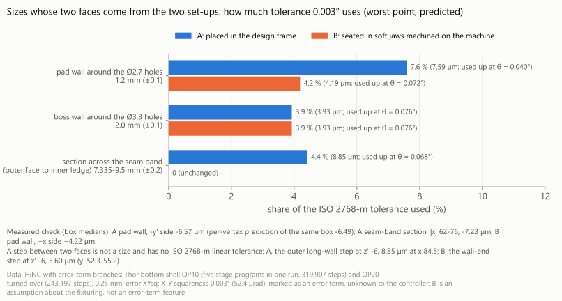
Before the first play, the plan corrected four of the designer agent's statements from the part's geometry, and three of them held as measured. The fourth named the seam band's wall thickness and the step there, 8.85 µm at x 84.5, as the first thing in A to use up tolerance, taking the band for a 3.5 mm wall under ISO 2768-m's ±0.1 mm. Sections of the design, read when the tolerance ledger was drawn up, show an inner ledge behind the seam band: the section there runs from the outer face to the ledge, 7.335 mm where |x| is up to about 78 and about 9.3–9.5 mm at x 80–84.5, both in the 6–30 mm class of ±0.2 mm. At the end of each wall where the seam's outer face comes from OP20, it thins by 7.23 µm at |x| 62–76, as predicted; the predicted worst, 8.85 µm at x 84.5, is 4.4 % of ±0.2. A step between two faces is not a size, and ISO 2768-m gives it no tolerance, so the plan's 8.9 % for the step, and 5.8 % for B's wall-end step, do not stand. The first size to use up tolerance in A is the 1.2 mm pad wall, at 7.6 %, the order the designer agent had given. The ledger was not a pass criterion; the record keeps this as a finding about the plan.
Vertices up to 0.18 mm off along sharp edges
In each of the three whole-case cuts with the error on, 0.41–0.57 % of the vertices lie more than 10 µm from the nominal cut; the largest in each, 157–177 µm, is at least 27 times the largest predicted deviation, 5.81 µm. Taken as the error, they would say the part was ruined; dismissed unchecked, they would leave a doubt. Every one was recomputed with an exact point-to-triangle distance: all are real, none an artefact of the distance search, and the control runs have none. 86–97 % of them lie in long rows along sharp edges running in x, such as the groove's edges, the wall top and the edge of OP10's last outer-contour pass, each row on the half of a wall where the error pushes that face into the material (two of B's vertices aside). Most rows keep one size along their whole length, whatever the error there, from 0.05 µm at x 1 mm to 4.4 µm at the ends, and the largest value exceeds half the diagonal of a 0.25 mm cell, 176.8 µm, by only 0.14 µm. The reading, inferred and not checked in HiNC's code: once an edge has moved a little, the mesh cuts the facet at that edge the other way. So these are not taken as cut deviations; sizes are read on measuring boxes kept off the edges and on the 1st and 99th percentiles.
The other nine are in the full record, among them where on the chain the error has to sit to leave a shape on the part, one pivot for two set-ups, the OP20 project's stored work offset of zero that every OP20 run typed over, the trimmed OP20 run whose solid block held material the real stock does not, the designer's size reference, which called an uncompensated machine's 24.4 µrad a calibrated one, why the whole case played no unmarked run, and OP20's memory, well above the plan's estimate of 4–12 GB.
The result
All fourteen plays ran to the end. The full plays reported no collision and no rapid move into the stock.
With the error on and the controller unaware of it, the tool tip of every cutting step, 224,167 in OP10 and 165,184 in OP20, sat where the formula written before the first play put it, δ = (X(cos θ − 1), −X sin θ, 0), within 8.36×10⁻¹⁴ mm: one formula for both set-ups, zero along program x = 0, δy within ±4.9 µm. Every step's machine coordinates are bit for bit those of the nominal run, and the control runs repeat the nominal runs bit for bit.
In OP10 alone the faces facing ±Y are sheared. The outer long walls' deviation runs along x at −52.34 and +52.34 µm/m, against ∓52.36 predicted, about ±4.4 µm at the ends. The inside faces move the same way, so the wall keeps its thickness (−0.053 µm); the end face reads −0.008 µm, and the floor stays green. A size cut in one set-up does not change.
On the finished part placed in the design frame (A), the two set-ups shear the part opposite ways. On the +y′ wall, the band OP10 cut runs at +52.34 µm/m and the 49° chamfer OP20 cut at −39.44 µm/m, against −39.49 predicted: a 49° face keeps only 0.754 of a move along y′. The seam between them, z′ −6 to −4.52, takes the deeper of the two cuts and reads −3.773 µm in both end boxes. At the x+ end of the +y′ wall, and at the x− end of the −y′ wall, its outer face comes from OP20 and stands 8.849 µm from the band OP10 cut at x 84.5, the 2θx predicted; at the other end the seam takes OP10's cut and leaves no step. The holes OP20 drilled and the bosses and pads OP10 cut move opposite ways by θx: the 2.0 mm boss wall around a Ø3.3 hole is 3.885 µm thicker on its +y′ side (3.93 predicted), and the 1.2 mm pad wall around a Ø2.7 hole 6.567 µm thinner on its −y′ side, in a box whose per-vertex prediction is 6.49 µm; on the hole's centre line the prediction is 7.59 µm. The same faces OP10 cut read the same before and after the turn-over: their medians in OP10's Diff and in the finished part's differ by 0.0000 µm in all five box pairs.
Seated in soft jaws machined on the machine (B), the long wall's band OP10 cut and the seam lie on one line, −52.36 and +52.36 µm/m on the two walls, the seam within 0.011–0.015 µm of the band: the seam is gone. The mismatch now runs along x, 2θy′. The part of the +y′ wall's +x end face that OP10 cut stands out 5.615 µm (5.63 predicted), 5.600 µm proud of the part OP20 cut above it; the boss wall's thick and thin sides move from ±y′ to ±x (−4.046 µm on the +x side, −3.93 predicted), and the pads' free sides change sign, +3.419 and +3.255 µm against +3.80 and +3.64 planned: the farthest of all boxes from the plan, still within its ±1.0 µm. The faces OP20 cut read the same as in A, in all 11 boxes to 0.0000 µm.
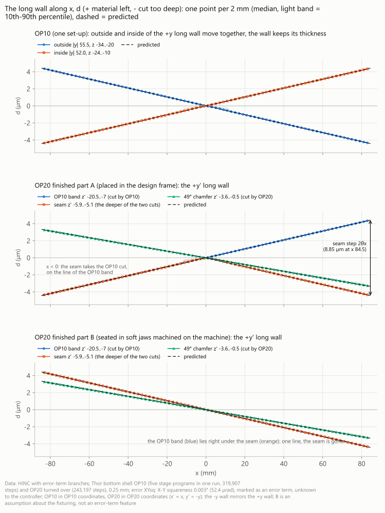
All 7 boxes of OP10 and the 22 of A and of B read their medians within 0.12 µm of the plan, except B's two pads, 0.39 µm off at most. The control runs cut the nominal part again: all their vertices lie within 0.1 µm of it, and the box medians within 3.4×10⁻⁷ µm, seven orders of magnitude below the error's ±4.4 µm. All twelve criteria written before the first play passed as written; three items of the first one, on the build, were read back when the work was closed: the Diff's detection radius and the workpiece chains' zero translation from the two projects saved at the build, and the case's other files left unchanged from git.
How much does it matter? The drawings give no tolerances, and the base case took ISO 2768-m. Sizes cut in one set-up do not change, and the 2.0 mm floor, though its two faces come from the two set-ups, is horizontal and does not move. What changes are sizes with one face from each set-up that are not horizontal. In A, the 1.2 mm pad wall around the Ø2.7 holes is the first: predicted 7.59 µm thinner at its worst point, 7.6 % of ±0.1 mm, so the machine would have to be out by 0.040°, 13 times this, before it is used up. The 2.0 mm boss wall uses 3.9 %, and the 7.335–9.5 mm section across the seam band 4.4 % of its ±0.2 mm. In B, the pad wall uses 4.2 %, the boss wall 3.9 %, and the seam section does not change. The largest mismatch on the part, A's 8.849 µm, is a step between two faces, not a size.
With the mark cleared, on the trimmed OP10 run, as a controller with calibrated kinematics would know the error, the run matched the marked run bit for bit: its ten step series and HiNC's Diff statistics, and its cut within 4.97×10⁻¹⁰ mm at every vertex. With plain three-axis G54 / G43 / G81 programs the controller takes the machine coordinates from the program, the work offset and the tool length, and never looks at the machine's chain, so knowing the squareness gives it nothing to change. To cut this part right, the machine has to be realigned, or the controller's own squareness compensation used, which HiNC does not simulate.
The study models one constant error only. A real three-axis machine also has X–Z and Y–Z squareness, angular errors of each axis, and positioning and straightness errors that vary along the travel; those, backlash, servo mismatch and heat do not fit a constant error term. The size and the sign were chosen: with the opposite sign every blue and red swap ends, and the sizes stay. The touch-off is assumed at program zero; elsewhere it only adds a constant shift. B models the seating only as the stock turned −2θ: how the jaws are cut, how the part bears on them and how clamping bends it are outside the model, and a real fixture may land between A and B. The plays are geometry only, with no cutting force, deflection or heat; the base case's long cutters bent up to 22 µm at the 95th percentile on the shell's finishing passes (35 µm on the chamfers), more than the ±4.4 µm here, and on a real machine the two add. Only the bottom shell was played. Everything is simulated; no part was cut.
What it brought
- For a machining engineer: on the same machine with the same 0.003°, one set-up only leans the faces facing ±Y by ±4.4 µm and leaves the wall, groove and floor thicknesses alone; turn the part over, and the faces the two set-ups cut stand twice as far apart, 8.85 µm at the ends of the long walls, while the thin walls around the holes come out thicker on one side and thinner on the other. The programs, the machine coordinates and the touch-off all look right. Where the mismatch lands depends on how the second set-up holds the part: placed in the design frame, on the long walls' seam and the holes' ±y sides; seated in soft jaws or on a plug machined on the same machine, the seam vanishes and the mismatch moves to the wall ends and the holes' ±x sides. This housing does not need a better machine: its tightest size is predicted to use 7.6 % of its tolerance. With plain three-axis programs, a controller with calibrated kinematics has nothing to change. In HiNC, a constant error measured on a machine can go into its model, to see its shape and size on your own part, across its set-ups, before anything is cut.
- For a teacher or a student: why turning a part over doubles the same machine error: a shear about Z changes sign on a part turned about X. Why an X–Y squareness moves only the faces facing ±Y, in proportion to x, and a face keeps only the part of the offset along its normal, 0.754 on the 49° chamfer and 0.806 on the countersink cone; where both set-ups cut, the deeper cut wins. Why the error has to sit between the two slides to cut a shape, while upstream of X it would only shift the part; why choosing the pivot means choosing the touch-off point, so one pivot serves two set-ups. And marked and unmarked branches as uncalibrated and calibrated kinematics, a difference that exists only under RTCP, a tilted working plane or CL playback.
- For someone deciding whether to use an agent with HiNC: from two accepted set-ups to one machine error's effect across a turn-over in a build and fourteen plays; the whole case at 0.25 mm took one job of 1 h 43 min on the shared 32-thread server, each OP20 play about 21 GB of memory. The predictions were written before the first play and met within 8.36×10⁻¹⁴ mm on the tool tip and within 0.39 µm in all 51 measuring boxes, 0.12 µm but for B's pads; the round trip through the turn-over lost 0.0000 µm. Where the record has to qualify, it says so as measured: a tolerance ledger in the plan that missed a ledge, the rows of far vertices along sharp edges, and OP20's memory, over the plan's estimate.
Read the full case record: the Thor enclosure's bottom shell with an X–Y squareness of 0.003°
How the enclosure, its set-ups and these programs were made: Jetson AGX Thor enclosure. The same kind of error on a part cut in one set-up: NISTIR 6868 test part, X–Y squareness of 6.87″.