Jetson AGX Thor Enclosure, Bottom Shell, on an X–Y Squareness of 0.003°: Turned Over, the Two Set-ups' Faces Stand 8.85 µm Apart at the Ends of the Long Walls; Seated in Soft Jaws Machined on the Same Machine, the Mismatch Runs along X and the Seam Is Gone
The Jetson AGX Thor enclosure case planned two set-ups for each
of the aluminium parts Antmicro publishes as open hardware, wrote its own CAM and Fanuc programs, and
accepted them in HiNC at a 0.25 mm grid. This page takes the bottom shell alone: 169 × 111 × 40.5 mm,
U-shaped and open at both ends, with 3.5 mm walls and a 2.0 mm floor. OP10 holds the blank in a vice by
its tab and machines the inside; OP20 turns the part over about X onto a plug fitted to the cavity, holds
it in soft jaws and machines the outside. Both are plain three-axis programs (G54, G43, G81; no
RTCP, no tilted plane, not CL).
On this page the agent puts a common geometric error into the case's three-axis skeleton machine: the X and Y travels 0.003° out of square. The Y slide, and the table with it, stands turned about Z on the X slide, 15.7 µm per 300 mm (the squareness between the X and Y motions of ISO 230-1, written EC0Y in this batch). It is one marked error term directly upstream of the Y axis branch, with the same value in the OP10 and the OP20 projects. Not one line of the programs was changed.
Within one set-up the error only shears the faces that face ±Y by −θx: ±4.42 µm at the ends of the long walls. Once the part is turned over, the shear turns round on the part: on the finished shell the faces OP10 cut lean by +θx and the faces OP20 cut by −θx, so the two set-ups' faces stand 2θx apart, 8.85 µm at the ends of the long walls. Where that mismatch lands depends on how OP20 holds the part:
- A, placed in the design frame (a probed touch-off, or an external fixture): the mismatch runs along y and grows with x. Each long wall's seam keeps a 2θx step at one end only, the +y′ wall's x+ end and the −y′ wall's x− end, 8.85 µm at x 84.5; at the other end the seam follows OP10's cut and has no step.
- B, seated in soft jaws or on a plug machined on this same machine: the long walls line up with the X travel again, the seam on them is gone, and the mismatch runs along x and grows with y. B is an assumption about the fixturing, not a feature of the error term: its stock is A's, turned a further −2θ about OP20's program zero.
Fourteen plays ran on a HiNC 3.2.46 development build with error-term branches, seven trimmed at a 1 mm grid and seven of the whole case at 0.25 mm: with the error terms off (the nominal run, whose cut is the ideal geometry of every geometry difference, or Diff, that follows), on with the error marked (the controller does not know it), and off again with a Diff (the control run, the noise floor); one trimmed run cleared the mark. What came out:
- The tool tip. On the 224,167 cutting steps of OP10 and the 165,184 of OP20, the tip's offset from the nominal run's lies on δ = (X(cos θ − 1), −X·sin θ, 0) within 8.36 × 10⁻¹⁴ mm (the length of the three-axis residual); δy stays within ±4.9 µm. The machine coordinates equal the nominal run's bit for bit at every step.
- OP10, one set-up. The outer long walls slope along x by −52.34 / +52.34 µm/m (predicted ∓52.36); the inner faces move the same way, so the wall keeps its thickness (outside plus inside −0.053 µm); the end face reads −0.008 µm.
- OP20, the finished part, A. The long walls' OP10 band slopes by +52.34 / −52.34 µm/m and the 49° chamfers OP20 cut by −39.44 / +39.45 µm/m (predicted ∓39.49): the two set-ups lean opposite ways. The seam takes the deeper cut, −3.773 µm at both ends, and its step at z′ −6 reads 8.849 µm at x 84.5 (predicted 2θx = 8.849). The holes and the bosses or pads around them move opposite ways by θx each: the boss wall outside a Ø3.3 hole is 3.88 µm thicker on one side, and the pad wall outside a Ø2.7 hole 6.57 µm thinner in its box (6.49 predicted vertex by vertex in the same box; 7.59 on the centreline).
- The round trip of export, turn-over and rebuild loses nothing: the same faces OP10 cut read the same in OP10's Diff and in the finished part's, the medians of five pairs of boxes 0.0000 µm apart.
- OP20, the finished part, B. The OP10 band and the seam run on one line (−52.36 / +52.36 µm/m), the seam 0.011 / 0.015 µm off the band. The OP10 part of the wall end stands out by +5.615 µm (predicted 5.63) under OP20's +0.015, a step of 5.60 µm; the boss's +x side reads −4.046 µm, and the pads change sign, +3.419 / +3.255 µm. The 11 boxes on faces OP20 cut are A's to 0.0000 µm.
- The tolerance ledger (the case's general tolerance, ISO 2768-m; the share used is the prediction at the worst point). In A the first size to use up its tolerance is the 1.2 mm pad wall outside a Ø2.7 hole: 7.59 µm on its centreline, 7.6 % of ±0.1 (6.57 µm measured in its box, 6.49 predicted there); the machine would have to be 0.040° out of square, 13 times this, before it is used up. In B the pad wall uses 4.2 % (4.22 µm measured on its +x side). The section across the seam band is not a 3.5 mm wall, as the plan had it: an inner ledge backs it, 7.335 mm up to |x| ≈ 78 and about 9.3–9.5 mm at x 80–84.5, both in the ±0.2 class; at its worst point, x 84.5, it is 8.85 µm thinner, 4.4 % of ±0.2 (at worst about 8.2 µm, about 4.1 %, in the 7.335 mm stretch; −7.23 µm measured at |x| 62–76) (dilemma 7).
- Whether the controller knows. The trimmed run with the mark cleared is bit for bit the marked one: a plain three-axis program does not read the machine chain, so a calibrated controller has nothing to change.
- The control. In all four control runs 100 % of the vertices lie within 0.1 µm of the nominal cut, and the boxes' medians within 3.4 × 10⁻⁷ µm.
- The mesh's extremes. In each of the three on runs of the whole case, 0.41–0.57 % of the vertices lie more than 10 µm from the nominal cut (176.9 µm at most). Checked one by one with an exact point-to-triangle distance, all of them are real; 86–97 % lie in long rows running in x along sharp edges (the rest mostly at the wall ends, |x| ≥ 78, and at corners of the pads, the ledge and the inner steps), and most rows keep one size along their whole length, whatever the error's size there (two rows in A and four in B vary along x by 2.7–112 µm). Read as the 0.25 mm mesh cutting an edge the other way (an inference, made without reading the mesh code), they are not used as cut deviations (dilemma 9).
- The cost, on a shared 32-thread server: the seven trimmed plays took 525 s; the seven of the whole case, one job, 1 h 43 min 17 s; each OP20 play peaked at 20.66–21.26 GB of memory.
Everything here is simulated; no part was cut.
The main picture. OP20's finished part A facing the +y′ long wall (looking along −y′; from top to
bottom: the 49° chamfer, the seam, the wall's OP10 band, the outer groove and a stretch near the wall
top), one camera alternating “Error terms on” (f-op20-on, whose stock is the OP10 on run's cut turned
over) and “Error terms off” (f-op20-control). With them on, the three stretches OP10 cut run from blue at
the left end (material left, about +4.4 µm) through green in the middle to red at the right end (about
−4.4 µm); the chamfer runs the other way, red at the left and blue at the right; and the narrow seam under
it is reddish at both ends. With them off, everything is green. The left end of the picture is x+
(inferred from how the camera was named). Diff colour scale ±0.005 mm (blue = material left, green = 0,
red = cut too deep, both signs weighted alike); 0.25 mm grid; a HiNC 3.2.46 development build with
error-term branches.
| The bottom shell at 0.25 mm on a HiNC 3.2.46 development build with error-term branches | Predicted before the first play | Measured |
|---|---|---|
| Tip minus nominal tip minus δ, the cutting steps (224,167 in OP10; 165,184 in OP20, A and B each) | 0 (the plan allowed 1 × 10⁻⁹ mm) | at most 8.36 × 10⁻¹⁴ mm (length of the residual) |
| δy on the cutting steps | within ±5.16 µm | OP10 −4.895…+4.895 µm; OP20 −4.887…+4.765 µm |
| Machine coordinates, on against nominal | the same | bit for bit at every step |
| OP10: outer long walls, slope along x, +y / −y | −52.36 / +52.36 µm/m | −52.34 / +52.34 µm/m |
| OP10: wall thickness (outer x+ box plus inner x+ box) | −0.05 µm | −0.053 µm |
| A: the long walls' OP10 band, slope, +y′ / −y′ | +52.36 / −52.36 µm/m | +52.34 / −52.34 µm/m |
| A: the 49° chamfers, slope, +y′ / −y′ | −39.49 / +39.49 µm/m | −39.44 / +39.45 µm/m |
| A: the seam boxes, x+ / x− | −3.77 / −3.77 µm | −3.773 / −3.773 µm |
| A: the seam's step at z′ −6, at x 84.5 | 2θx = 8.849 µm | 8.849 µm |
| A: the 1.2 mm pad wall, −y′ side | −7.59 µm on the centreline; −6.49 µm vertex by vertex in the box | −6.567 µm in the box |
| Round trip: five boxes of faces OP10 cut, OP10's Diff against the finished part's | the same (the plan allowed 0.5 µm) | 0.0000 µm |
| B: the OP10 band and the seam, slope, +y′ / −y′ | −52.36 / +52.36 µm/m | −52.36 / +52.36 µm/m |
| B: the +y′ wall's +x end face, OP10's part | +5.63 µm | +5.615 µm |
| B: the 11 boxes on faces OP20 cut, against A | 0 | 0.0000 µm |
| Unmarked against marked (trimmed OP10) | the same | the ten series keys bit for bit; the cut's vertex distances bit for bit |
| The four control runs against nominal | 0 | 100 % of the vertices within 0.1 µm |
| The whole-case job / peak memory of an OP20 play | 1.6–2.5 h / 4–12 GB (the plan's estimates) | 1 h 43 min 17 s / 20.66–21.26 GB |
The case
The base case tells how the agent planned the enclosure's parts in two set-ups each, wrote its own 2.5-axis CAM and Fanuc programs, and accepted them in HiNC, where the places the programs would have crashed, broken a tool or missed stock were caught before any cut. That machine was built as designed, with no error. This page puts one geometric error into the same machine and asks three questions:
- What the same machine error looks like, and how large it is, within one set-up and between the two set-ups of a part turned over.
- Where the doubled mismatch lands on the part, and how it changes with the way OP20 holds the part.
- How far out of square this machine would have to be before the enclosure's general tolerance is in trouble.
What the agent was given:
- The two accepted projects and their programs.
- The OP10 project,
bottom-shell-OP10: a 175 × 117 × 49 blank held by a vice on its lowest 8.5 mm; G54 (−381, −203, −513.4639999999999). Its programs are the whole OP10 program cut at its tool changes into five,NC/bottom-op10-s1.nc…s5.nc: T1 facing and the outside profile, roughed and finished; T4, the T-slot cutter, for the outer grooves; T1 again for the cavity roughed in levels, the inner walls, the bosses, the pads and the flats; T2 for the corner rests; T3 for a narrow gap. The accepted case handed the stock from one program to the next as a recorded meshed geometry (a.wctfile). - The OP20 project,
bottom-shell-OP20: its stock is the OP10 cut, exported and turned over about X by the base case's turn-over script, (x, −y, −z − 40.536), seated on the plug and held by soft jaws on the wall top. One program,NC/bottom-op20.nc(19,308 lines): T1 faces the tab off and finishes the outside profile down to Z−6; T5, a D6 ball, cuts the 49° chamfers along both long edges; T7, T8 and T9 drill 7 × Ø2.7, 4 × Ø3.3 blind and one Ø5.1; T6, a D2 ball, cuts the seven countersinks. The project stores G54 as (0, 0, 0): the accepted case set it with P0 after every reset. - The machine
Empty-wXYOZSt, the three-axis skeleton both projects share (a machine with no model): table side O→base→X→Y→w, tool side base→Z→S→t; X below, Y above; the Spindle role on Z→S.
- The OP10 project,
- HiNC's error terms. An axis or the spindle of the machine chain can be given an error term, a
static branch of its own just before the axis's branch: it carries a measured error rather than part of
the design. The controller,
XyzabcSolver, which turns NC into machine coordinates (RTCP and tilted planes included), always solves on the nominal chain, taking the marked branches as absent. While the project's Enable Error Terms switch is on, the simulated machine keeps the marked branches as it moves, cuts and checks collisions. So the error is cut into the part, as on a real machine whose controller does not know it. Without RTCP or a tilted plane the machine coordinates come from the program and its offsets alone, so every error in the chain is cut into the part, marked or not (Error-Term Branches). - Touch-off and P0. HiNC's P0 measures program zero on the nominal chain. On a real machine, the work offset found by touching off already holds the constant shift the error causes at the touch-off pose (work offsets on a machine with error terms).
- A placement rule. HiNC's product owner ruled on 2026-10-06 that an error term goes only directly
upstream of a role branch, an axis or the spindle, on a new anchor named after the axis with
errafter it. - The request. HiNC's product owner asked for error-term showcases built on accepted cases, with the heavy runs on a shared server.
What nothing states:
- Which error. It had to be one that crosses the two set-ups and changes sign on the part. The X–Y squareness turns about Z, and a part turned over about X sees that turn with the opposite sign; and the long walls' two bands, the holes and their bosses, the holes and their pads fall into different set-ups.
- How OP20's stock carries the error across. OP20's on run has to start from what OP10's on run cut,
and the recorded
.wctdoes not carry across (dilemma 4). - Where the doubled mismatch lands. That depends on how OP20 holds the part, which the error term itself cannot decide; the agent played both ways (dilemma 5).
- Whether a 0.25 mm grid reads it. The largest deviation of a single face, 4.42 µm, is 1.8 % of the cell width. A 0.25 mm trial run of another case in this batch, RPTU part 4, with the same value read ±2.7 µm that still followed the error linearly, so the error was not magnified.
Among the error-term cases so far, this is the first whose part is turned over between two set-ups: one error on the machine, opposite signs on the part.
What the agent built
Each value is marked read (from the base case or a document), derived (computed from what was read), chosen (the agent's decision) or measured (read back after the build or a play). θ is the error's angle, 0.003°.
| Value | Source | |
|---|---|---|
| Meaning | The X and Y travels out of square: the Y slide, carrying the table, the fixture and the part, rides on the X slide turned about Z by θ, so the +X and +Y travels meet at 90° + θ (the squareness between the X and Y motions of ISO 230-1, written EC0Y in this batch). For a part on the table the Y travel runs along the part's y and the X travel along (cos θ, −sin θ): in each set-up the faces that face ±Y are sheared by δy = −θx; the faces that face ±X, the horizontal faces and anything on x = 0 stay where they are | chosen: the kind of error; derived: its effect on the part |
| Size | 0.003° (52.36 µrad, sin θ = 5.236 × 10⁻⁵) = 15.71 µm per 300 mm; 4.42 µm at each end of the long walls, x ±84.5, and 8.85 µm between the two set-ups | chosen: a typical value, not magnified; derived |
| Against a measurement | In the upper half of the range this batch's design brief gives for the squareness of linear axes, 5–20 µm per 300 mm; not a measurement of any machine. Holub et al. (2020) measured a three-axis vertical machining centre with a laser tracer: its X–Y squareness before compensation was 24.4 µrad = 0.0014° (Applied Sciences 10, 6233, LTc1 in Fig. 6, read off the bar chart); this case is about 2.1 times that. A trial run on RPTU part 4 in this batch and the JMMP deep-slot case use the same value | read; chosen |
| Where | Directly upstream of the Y axis branch. The old X→Y is split in two: X→Yerr, named XYsq, carries a Static Rotation of 0.003° about (0, 0, 1) with its pivot at (−381, 0, 0) in the X anchor's frame, marked as an error term; the Y axis' Dynamic Translation (0, −1, 0) moved onto Yerr→Y, still named Y, and Axis Y was bound to it again, its values unchanged |
chosen, following the owner's ruling |
| Pivot | (−381, 0, 0): the spindle axis at the touch-off pose of both set-ups (G54 X −381, the tip at program zero), in the X anchor's frame. A turn about Z ignores z, so OP10's touch-off tip (base z 486.536) and OP20's (512.536) both lie on that line, and one pivot holds for both set-ups | derived (the design's derivation, steps 2–4) |
| The chain | O→base→X→Yerr→Y→w; the tool side base→Z→S→t unchanged; the same in both projects | measured (read back after the build) |
| Read back | The values read back equal the values requested (axis, angle, pivot), and XYsq is the same in both projects; the other six branches (NewAnchor-001, X, Z, NewAnchor-006, NewAnchor-005, tooling-location) unchanged; Y's values and role unchanged (the branch has a new guid); the roles check empty before and after; no message on loading or reopening |
measured |
| Work offsets | OP10: the project's stored G54 (−381, −203, −513.4639999999999) is the touch-off value, and no run typed one in. OP20: the project stores 0, and all seven runs typed in what P0 reads on the nominal chain, (−381, −203, −487.4644626312256): the fixture's WorkpieceMount 122.53553736877441 + the table mount 390 − the tool mount 1000. The on runs typed the same value as the nominal ones: a touch-off finds the nominal G54 | measured (each run's work offsets before the run and as typed); derived |
The branch is named XYsq, the name the batch's error-term tool gave it when it inserted the branch. In
the topology graph only the anchor Yerr stands between it and the Y axis branch, the shape the manual
describes for an axis' error term, and the graph gives it the error-term badge.
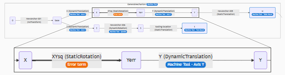
The machine-tool cluster (GeneralMechanism) in the Topology column of the Equipment page. A new anchor, Yerr, stands between X and Y. XYsq (a Static Rotation, X → Yerr, read back as 0.003° about (0, 0, 1), pivot (−381, 0, 0) mm in the X anchor's frame) carries the orange “Error term” badge; the Y axis' Dynamic Translation (“Machine Tool · Axis Y”) sits on Yerr → Y; the tool side base → Z → S → t is unchanged. Below, the X → Y stretch of the same capture, magnified. Captured on the OP20 error-term project (the OP10 project's chain is the same); a HiNC 3.2.46 development build with error-term branches, English interface.
Why the X–Y squareness, and why upstream of Y (the designer agent's derivation):
- Turning the part over about X changes the sign of a turn about Z on the part, and the long walls' two bands, the holes and their bosses, the holes and their pads fall into different set-ups. This is the error that makes “doubled between the set-ups” appear.
- The X–Y squareness has to sit between the two slides. Upstream of X (between base and X, about Z) both slides and the table would turn together, and the tip offset would become (Rz(−θ) − I)(0 − c), a constant: a shift a touch-off takes out, with no shape error on the part. On this machine X is below and Y above, so directly upstream of the Y axis branch is exactly between the two slides, and it follows the owner's ruling.
- A spindle tilt would leave only sub-micrometre effects with these tools of D20 and smaller, so it was not chosen.
Where the tip goes: the predictions written before the first play.
- θ = 5.235987755982989 × 10⁻⁵ rad; X, Y and Z are the nominal run's tip Cl in program coordinates. No branch of the machine file turns, the spindle axis is base x = 0, y = 0, and the tip in the X anchor's frame is (X − 381, 0, ·). The Static Rotation turns the table by +θ against the X slide, so the tip moves against the part by δ = Cl(on) − Cl(nominal) = (Rz(−θ) − I)(X, 0, ·) = (X(cos θ − 1), −X·sin θ, 0).
- The same formula for both set-ups, independent of Y, Z and the tool length; 0 on the whole line program x = 0, so a touch-off finds the nominal G54.
- Range: OP10's program X runs −98.5…98.5 (the T-slot cutter of s2), so δy ±5.16 µm; |δx| ≤ 1.35 × 10⁻⁷ mm.
- An affine fit δ = A·p + b should give A = [[cos θ − 1, 0, 0], [−sin θ, 0, 0], [0, 0, 0]] = [[−1.371 × 10⁻⁹, 0, 0], [−5.236 × 10⁻⁵, 0, 0], [0, 0, 0]] and b = 0.
- Machine coordinates: on, unmarked, control and nominal the same at every step (plain three-axis programs).
What the part keeps, as the signed distance d of the on cut from the nominal cut along the face's normal (positive = material left = blue; negative = cut too deep = red). The cutter is rigid and only translates, so a cut face is about the nominal face carried by (x, y, z) → (x cos θ, y − x sin θ, z); the shear of the cutter's own section is at most Rθ/2 = 0.16 µm (D12). In the program coordinates of the set-up that cut it, each face reads d ≈ −θ·x·n_y:
- OP10 (OP10's coordinates are the design STL's): the +y long wall's outside −θx, the −y wall's outside +θx; the inside faces move the same way (their normals are opposite, so d takes the opposite sign), so each wall moves whole and keeps its thickness; the bosses, pads and rails move whole by (0, −θx); the end faces −84.5·θ²/2 = −1.2 × 10⁻⁴ µm, the horizontal faces 0.
- OP20, the finished part, A (OP20's coordinates x′ = x, y′ = −y, z′ = −z − 40.536; x′ is written x
below): on the turned part the faces OP10 cut move by δ = (0, +θx), the faces OP20 cut by (0, −θx);
where both cut, the deeper cut stays.
- The long walls' OP10 band (z′ −40.5…−6): the +y′ face +θx, the −y′ face −θx.
- The 49° chamfers (T5; the design face 0.7543y′ + 0.6566z′ = 38.588): the +y′ chamfer −0.754θx, the −y′ chamfer +0.754θx, ∓3.34 µm at the ends.
- The seam (z′ −6…−4.52: OP10's outside profile is finished down to z′ −4.482, OP20's T1 finishes the outside profile at Z−6, and the R3 ball of T5's lowest level meets the wall at z′ −4.52): the deeper cut, −θ|x|, red at both ends. At the +y′ wall's x > 0 end (and the −y′ wall's x < 0 end) the outside follows OP20's cut while the face behind it is OP10's, and at z′ = −6 a step of 2θ|x| stands (8.85 µm at x 84.5).
- A Ø3.3 blind hole (OP20) in a Ø7.33 boss (OP10): the hole and the boss move opposite ways by θx each (1.96 µm at x 37.5), so the 2.0 mm wall is 3.93 µm thicker on one side and 3.93 µm thinner on the other.
- A Ø2.7 hole and its countersink (OP20) through a Ø5.1 pad 0.98 mm high (OP10): the 1.2 mm pad wall changes by ±2θx (7.59 µm at x 72.504); the countersink cone (half-angle 36.3°) takes a normal component of 0.806θx.
- The end faces, the floor face z′ = 0, the cavity floor and the centre Ø5.1: 0.
- OP20, the finished part, B (the stock turned a further −2θ = −1.047 × 10⁻⁴ rad about Z through OP20's program zero, the long walls along the X travel again): the faces OP10 cut move by δ = (2θy′, −θx), the faces OP20 cut by (0, −θx) as before. The long walls' two bands slope alike and the seam is gone; the mismatch becomes 2θy′, along x: the OP10 part of the +y′ wall's +x end face +5.63 µm (5.81 at the corner); the boss's +x side −3.93 µm and its +y′ free side −1.96 µm; the pads' free sides change sign against A. The faces OP20 cut are A's.
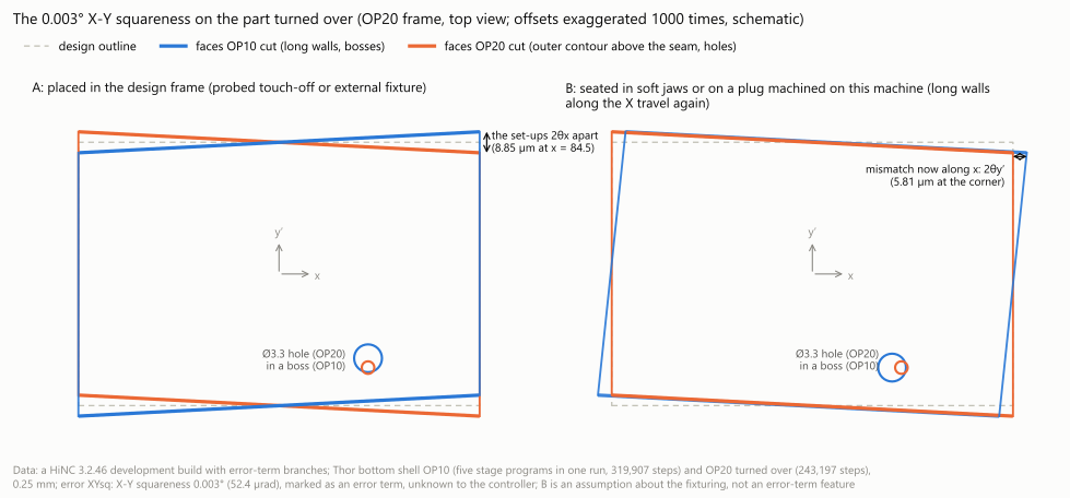
Schematic (OP20 frame from above, offsets exaggerated 1000 times). Placed in the design frame (A), the faces OP10 cut (blue: long walls, bosses) shear by +θx on the turned-over part and the faces OP20 cut (orange: the outer contour above the seam, the holes) by −θx; they cross at x = 0 and stand 2θx apart at the ends of the long walls (8.85 µm at x = 84.5). Seated in soft jaws machined on the same machine (B), OP10's faces turn a further −2θ, the long walls run parallel to OP20's faces, and the mismatch moves along x, 2θy′ in size (5.81 µm at the corner). B is an assumption about the fixturing, not a feature of the error term.
The runs:
| Run | Project / run set | Program | Grid | Switch / XYsq |
Stock | Purpose |
|---|---|---|---|---|---|---|
| t-op10-nominal | OP10 / trim | s1 | 1 mm | off / marked (not in effect) | the blank | exports the trimmed nominal cut |
| t-op10-on | OP10 / trim | s1 | 1 mm | on / marked | the blank | controller unaware; Diff, export |
| t-op10-control | OP10 / trim | s1 | 1 mm | off / marked (not in effect) | the blank | noise floor; Diff, export |
| t-op10-unmarked | OP10 / trim | s1 | 1 mm | on / mark cleared | the blank | controller aware; Diff, export |
| t-op20-nominal | OP20 / trim | bottom-op20.nc |
1 mm | off | the blank turned over | exports the trimmed nominal cut |
| t-op20-on | OP20 / trim | the same | 1 mm | on | the blank turned over | Diff, export |
| t-op20-control | OP20 / trim | the same | 1 mm | off | the blank turned over | noise floor; Diff, export |
| f-op10-nominal | OP10 / full | s1–s5 in one run | 0.25 mm | off | the blank | exports the nominal cut (the ideal geometry, and the stock of OP20's nominal and control) |
| f-op10-control | OP10 / full | the same | 0.25 mm | off | the blank | noise floor; Diff, export |
| f-op10-on | OP10 / full | the same | 0.25 mm | on | the blank | Diff, export (the stock of OP20's on runs) |
| f-op20-nominal | OP20 / from-nominal | bottom-op20.nc |
0.25 mm | off | OP10's nominal cut turned over | exports the nominal cut (the ideal geometry) |
| f-op20-control | OP20 / from-nominal | the same | 0.25 mm | off | the same | noise floor; Diff, export |
| f-op20-on | OP20 / from-on | the same | 0.25 mm | on | OP10's on cut turned over (A) | Diff, export |
| f-op20-seated | OP20 / from-on-seated | the same | 0.25 mm | on | the same, turned a further −2θ about program zero (B) | Diff, export |
XYsq is marked in every run of both projects and only the switch differs; only t-op10-unmarked cleared
the mark.
Common to every run:
- Physics off. This case looks at geometry only; cutting force, deflection and heat are outside it (the base case accepted its programs with physics on, so the costs below do not compare with its own).
- Collision detection on, pause on failure off; one step per spindle revolution (Feed Per Cycle).
- The Diff (Geometry Validation): the ideal geometry is the cut
the same project's nominal run exported; a detection radius of 1 mm and a colour scale
(
DiffVisualRadius) of ±0.005 mm, both read back from the two project files saved at the build; the real error, not magnified. - A restarted instance for every run, the project loaded from its file, so each peak memory is that run's own.
- The per-step series record Cl.X/Y/Z (the tip in program coordinates), MC.X/Y/Z, FileNo, LineNo, IsTouched and ToolId.
How the agent managed the work
- Criteria and predictions first. The designer agent's full derivation, the two case files the error-term tool reads (with the parking program and the turn-over script for the stock) and the plan with its twelve numbered criteria were all committed before the first play. The build ran at 03:38:47 on 2026-10-07 and the first play started at 03:40:36. Where the design differs from the case files and the plan, the latter two win.
- Two projects, two case files. The error-term tool takes one project per case file, so OP10 and OP20 were each saved as an error-term project of their own; Save As writes the machine file beside the project, and both machine files carry the same error.
- Trimmed runs first, seven at 1 mm, 03:40:36–03:49:21, outside the shared lock:
t-op10:bottom-op10-s1.ncalone (T1 facing and the outside profile, 1,182 lines, 58,993 steps, X −95.5…95.5, across the whole long wall), nominal, on, control and unmarked.t-op20: the whole ofbottom-op20.nc(243,197 steps) on OP10's raw blank turned over, a stock of 12 triangles instead of the roughly 1.6 million of the real one, nominal, on and control. These checked the typed G54, the stock swap, the per-step formula, and five tool changes in one run without a reset (each of the six tools has contact steps).
- The whole case as one job of seven runs at 0.25 mm, the case's acceptance grid, 17:56:16–19:39:33,
in a fixed order, because OP20's stock comes from OP10's cut:
f-op10: the five programs in one run without a reset: nominal (exporting the nominal cut), control, on (exporting the on cut).- The two OP10 exports turned over with the base case's matrix, (x, −y, −z − 40.536), B's copy turned a further Rz(−2θ), not decimated. This and an instance restart took 32 s between OP10's last run and OP20's first.
f-op20: nominal and control on the nominal stock, A and B on the on stock and its turned copy.
- The nominal cut is the ideal geometry. Each project's nominal run exported its cut, which became the ideal geometry of that project's Diffs: 1,587,794 triangles for OP10 and 1,674,804 for OP20 (103,488 and 79,204 trimmed). The Diff then holds only what the error changes, not the marks the toolpath itself leaves.
- NC played, not records. OP10's own
Record Meshed Geometryentries were all switched off; in OP20 onlybottom-op20.ncis on, with the parking program in the list and off. Each run with a Diff recorded its final stock for the pictures. - Every number from the records. The agent's analysis script computes the step comparisons, mesh distances, boxes, slopes, cost and verdicts on this page from the run records, keeps each number with its source, and can be run again. Every vertex more than 10 µm off was measured again on the server with an exact point-to-triangle distance against the nominal cut. The agent running the case judged the criteria with scripts of its own as a cross-check.
- Pictures in both interface languages, from the recorded stock put back on the canvas with its Diff, not from a replay. The canvas carries no interface text, so at one camera the English and Chinese captures are the same pixel for pixel; only the labels of the alternating pictures, the topology graph and the chart text follow the language.
- Sharing a server. The whole-case job waited for the lock that lets one whole-case job run at a time on the shared server, and its cost below counts only the time it held the lock.
- Where a person stepped in. HiNC's product owner asked for error-term showcases built on accepted cases, with the heavy runs on a shared server, and ruled on 2026-10-06 that an error term goes only directly upstream of an axis or the spindle. The error, its size, its pivot, the two ways of seating the part, the predictions and the criteria are the agents' own: the designer agent worked them out, and the agent that ran the case wrote them into the plan. The criteria and their verdicts are listed under Results and benefits.
The dilemmas
Each one is told as its situation, the risk if it had been missed, how it was noticed, the resolution, and the evidence that the resolution held.
1. Where in the chain the error sits
- Situation. The X–Y squareness is an angle between the two slides, and the owner's ruling puts an error term only directly upstream of an axis or the spindle.
- Risk. Upstream of X (between base and X, about Z), both slides and the table turn together and the tip offset becomes (Rz(−θ) − I)(0 − c), a constant: a touch-off takes it out whole, and the part shows nothing.
- How noticed. The designer agent's derivation.
- Resolution. Directly upstream of the Y axis branch. On this machine X is below and Y above, so that is exactly between the X slide and the Y slide.
- Evidence. The tip offset varies with X as (X(cos θ − 1), −X·sin θ, 0), within 8.36 × 10⁻¹⁴ mm (the length of the three-axis residual).
2. One pivot that holds for both set-ups
- Situation. A Static Rotation needs a pivot. The two set-ups touch off at different heights (the tip at base z 486.536 and 512.536), and the part is turned over between them.
- Risk. A wrong pivot adds a constant shift to the part, a different one in each set-up, which would look like a wrong program zero.
- How noticed. The design's derivation, steps 2–4: both set-ups have G54 X and Y at (−381, −203), and at the touch-off pose the spindle axis lies at (−381, 0) in the X anchor's frame for both; a turn about Z ignores z.
- Resolution. The pivot at (−381, 0, 0), on that vertical line. The deviation is 0 along the whole line program x = 0, for any y, z and tool length, so a touch-off finds the nominal G54, and the on runs type no other work offset.
- Evidence. The program-zero offset of the affine fit, |b| ≤ 2.67 × 10⁻¹⁴ mm, in OP10 and OP20.
3. OP20's base project stores G54 as 0
- Situation. The OP20 project,
bottom-shell-OP20, stores G54 (0, 0, 0); the accepted case set it with P0 after every reset, and the error-term tool does not measure G54. - Risk. Left as stored, the nominal run's whole program would be 381 / 203 mm off. The design's −487.4645 is rounded, 0.04 µm from what P0 reads.
- How noticed. The designer agent reading the project file.
- Resolution. Every OP20 run typed in what P0 reads on the nominal chain, (−381, −203, −487.4644626312256) (the fixture's WorkpieceMount 122.53553736877441 + 390 − 1000); the tool reads the row back right after typing it and stops on a difference over 1 × 10⁻¹². The on runs typed the same value.
- Evidence. In all seven OP20 runs G54 was 0 before the run and this value as typed; the program-zero offset of the tip is |b| ≤ 2.65 × 10⁻¹⁴ mm.
4. How the stock crosses the turn-over
- Situation. OP20's on run has to start from the part OP10's on run cut, or the error does not carry from OP10 into the finished part.
- Risk. The
.wctOP10 recorded would spare building the stock from a mesh of about 1.6 million triangles, but it sits in OP10's workpiece frame: using it would mean turning OP20's workpiece chain (GeomAnchor→FixtureMount 180° about X, z −40.536), a change to the base project. Going through the STL instead, the round trip of export, turn-over and rebuild might wipe out a difference of a few micrometres. - How noticed. The designer agent reading both projects' workpiece chains.
- Resolution. OP10's nominal and on exports turned over with the matrix the base case's turn-over script uses, B's copy turned a further Rz(−2θ), not decimated. The plan added a round-trip check (criterion 10), with a ×10 magnified version for the pictures should it fail.
- Evidence. The medians of five pairs of boxes are 0.0000 µm apart, and no ×10 version was needed. The price is the memory and time of every OP20 play (dilemma 13 and what the runs cost).
5. How OP20 holds the part: A or B
- Situation. HiNC places OP20's stock in the design frame, as the base case does (A, which stands for a probed touch-off or an external fixture). On a real machine whose plug and soft jaws were machined on that same machine, the part seats with its long walls along the X travel again (B).
- Risk. Playing A alone would present "the doubled mismatch lands on the long walls' seams" as the error's only outcome; presenting B as the error term's effect would mislead too, since B is an assumption about the fixturing.
- How noticed. The designer agent, deriving the displacements after the turn-over.
- Resolution. Both were played. B's stock is A's turned a further −2θ about OP20's program zero, and the page and every caption of B say that it is an assumption.
- Evidence. B's long-wall bands run on one line (the seam against the band −0.011 / −0.015 µm), and the mismatch moves to the wall end (+5.615 µm) and to the ±x sides of the bosses and pads; the 11 boxes OP20 cut equal A's within 0.0000 µm; B's tool tips and machine coordinates equal A's bit for bit.
6. The trimmed OP20 run cuts at rapid on a solid block
- Situation. The trimmed
t-op20used OP10's raw blank turned over as its stock, to avoid building one from the STL. The block has no cavity and still has material round the outside below z′ −4.482, while the toolpath was planned for the real stock. - Risk. The toolpath meets material the real stock does not have and reports rapid cuts, which looks like a build mistake.
- How noticed. The plan foresaw it, in how the runs go and in criterion 3.
- Resolution. Recorded, not judged a failure; the trimmed runs judge only faces OP20 cuts, and nominal and on have to match.
- Evidence.
Play-RapidCut--Detectedtwice in each of nominal, on and control, the same in all three; none in the four whole-case OP20 runs on the real stock.
7. Four statements of the design the plan corrected from the geometry, one of them wrongly
Situation. From sections of the design STL, the plan corrected four statements of the designer agent:
- the two faces of an OP10 long wall get opposite colours (their normals are opposite), not the same;
- seen from inside the cavity, the bosses and pads move opposite to the holes but show the same colour on the same side;
- the seam is z′ −6…−4.52 (the D6 ball's R3 meets the wall at z′ −4.52), not −4.99;
- the first thing in A to use up the tolerance is the seam band's wall thickness and the seam's step (8.85 µm at x 84.5), not the pad wall.
Risk. The fourth correction was wrong. Behind the seam band, z′ −6…−4.52, the long wall has an inner ledge (a rail: y′ 48.165, z′ −7.98…−2.0, |x| up to about 78; 46.0–46.2 at x 80–84), so the section from the outside face to the inside is 7.335 mm up to |x| ≈ 78 and about 9.3–9.5 mm at x 80–84.5. Both fall in ISO 2768-m's 6–30 mm class, ±0.2, not under a 3.5 mm wall's 0.5–6 mm, ±0.1. Written as planned, the page would name the wrong size as the first to go.
How noticed. The analyst, building the tolerance ledger, read where the inside face lies on the design STL's sections at x = 0.1…84.1, and on the nominal cut.
Resolution. Rewritten as read and measured:
- The seam band's section thins by 2θ|x|: −7.23 µm measured at |x| 62–76, in the 7.335 mm stretch (predicted −7.23). The predicted worst point is x 84.5, in the 9.5 mm stretch: 8.85 µm thinner, 4.4 % of ±0.2; in the 7.335 mm stretch about 8.2 µm at worst, about 4.1 %.
- The first in A is the 1.2 mm pad wall, 7.59 µm predicted = 7.6 % (used up at θ 0.040°), as the design had it.
- The 8.85 µm step at the seam stays the largest mismatch on the part, but a step between two faces is not a size, and ISO 2768-m's tolerances for lengths do not cover it: the plan's 8.9 % against ±0.1 does not hold. For B the plan ranked first the wall end's step at z′ −6 (5.81 µm at the corner, 5.8 %, 0.052°), likewise a step against ±0.1, which does not hold either; B's first is the pad wall, 4.19 µm predicted = 4.2 % (0.072°).
This is a finding about the plan, not a new verdict: the tolerance ledger is not one of the plan's criteria. The first three corrections hold, and the measurements agree with them: OP10's two faces read +3.719 against −3.773 µm; the +y′ sides of the boss and of its hole are both blue (+1.972, +1.913 µm) and the −y′ sides of the pad and of its countersink both red (−3.686, −3.041 µm), shown by box values only, since the plan's picture of A from inside the cavity was not captured; the seam boxes read −3.773 µm.
Evidence. The analysis's section readings of the design STL and its tolerance numbers, kept with the results.
8. The reference for the size had “before” and “after compensation” the wrong way round
- Situation. The designer agent described the 24.4 µrad of Holub et al. (2020) as measured on “a three-axis vertical machine calibrated with a laser tracer”.
- Risk. Reading a value from before compensation as a calibrated one says “even a well calibrated machine is this far out”, which overstates the basis of the typical value.
- How noticed. Checking the plan against the paper's Fig. 6, where LTc1 is before compensation.
- Resolution. The plan and the OP10 case file say “before compensation” (the OP20 case file does not cite the value); this case's 0.003° is about 2.1 times it, a typical value, not a measurement of any machine.
- Evidence. The plan's row on the error's size and the OP10 case file's rationale.
9. 0.41–0.57 % of the vertices more than 10 µm off
- Situation. The three on exports of the whole case read at most |d| = 162.7 / 176.9 / 157.3 µm (OP10, A, B), more than 27 times any predicted deviation (the largest, 5.81 µm, at B's wall-end corner).
- Risk. Taken as the error, they would say the part was cut wrong; set aside without a check, that claim would not stand.
- How noticed. The agent running the case asked for an exact point-to-triangle distance before anything was said about them.
- Resolution. Every vertex beyond 10 µm was measured again on the server against the nominal cut, triangle by triangle: all 3,303, 4,868 and 4,466 of them are real, none an artefact of the distance search; the two whole-case control runs have none. Grouped by (|y|, z), 86 / 90 / 97 % lie in 5 / 9 / 11 long rows along sharp edges running in x; each row lies on one half of a wall, and most rows keep one size along their whole length; the largest equals half a cell's diagonal, 0.25/√2. The reading, an inference, is that the 0.25 mm mesh cuts a sharp edge the other way once the edge has moved a little, so they are not used as cut deviations; every size on this page comes from boxes clear of the edges and from the 1st and 99th percentiles.
- Evidence. The exact distances, kept with the results; the rows in the control runs and the extremes of the mesh distance. The reading is an inference, made without reading the mesh code, and not every row keeps one size: two in A and four in B vary along x by 2.7–112 µm.
10. Whether to run the whole case unmarked
- Situation. The plan put the run with the mark cleared in the trimmed set only.
- Risk. One piece of whole-case evidence less; or one more OP20 play, about 21 GB, for the same result.
- How noticed. Both are plain three-axis programs (no
G43.4, noG68.2, not CL): the controller computes the machine coordinates from the program and its offsets alone, so the unmarked run has to equal the on run bit for bit, and if it did not, that would be a finding to record. - Resolution. Played once, on
t-op10; no whole-case unmarked run and no unmarked capture, so there is no picture alternating “Controller unaware” and “Controller aware”. - Evidence.
t-op10-unmarkedequalst-op10-onin all ten series keys, in itsDiff--Statsand in its export's distances.
11. “The original object” and a new guid
- Situation. Criterion 1 calls
Yerr→Y“the original Dynamic Translation object”; after the insertion that branch has a new guid. - Risk. Judged to the letter, the criterion could fail; or a reader could think the Y axis was replaced by another motion.
- How noticed. Comparing the topology before and after the build.
- Resolution. Judged by the test the plan names in brackets,
movedValuesSame: the values (axis (0, −1, 0), Step 0) and the role Axis Y are the same, and the other six branches keep their guids. The axis branches of the batch's other cases got new guids in the same way. - Evidence. The build records' topology before and after (
Y's guid new, the six others unchanged) and theirmovedValuesSame.
12. IsTouched changes with the error
- Situation. The on and nominal runs have the same steps, lines and machine coordinates, but whether a
step touches the stock differs on a few: 33 steps in
t-op10-on(17 fewer touching, 46,498 against 46,515), and in the whole case 268 inf-op10-on, 1,397 inf-op20-onand 1,458 inf-op20-seated. - Risk. The steps the comparison covers would depend on which run defines a cutting step.
- How noticed. The step-by-step comparison.
- Resolution. A cutting step is always one on which the nominal run has contact, and the residual was also computed over every step (at most 1.26 × 10⁻¹³ mm in length); the conclusion does not change.
- Evidence. The step pairs in the analysis; the split by tool is under the tool tip.
13. OP20's memory above the plan's estimate
- Situation. The plan estimated a peak (VmHWM) of 4–12 GB per OP20 run; all four whole-case runs peaked at 20.66–21.26 GB (19.24–19.80 GiB).
- Risk. Reaching the plan's 24 GB stop line, or crowding the other instances on the server.
- How noticed. Each run's VmHWM.
- Resolution. Within the stop line; the runs were finished and their peaks are reported as measured. The agent running the case saw the peak come in the first minutes, while the stock is built from its mesh of about 1.6 million triangles; the records hold only the peak, not when it came. The trimmed runs, on a 12-triangle block at 1 mm, peaked at 2.30–2.42 GB.
- Evidence. The VmHWM in each run's record.
Results and benefits
Measured on a HiNC 3.2.46 development build with error-term branches, with physics off: the whole case at 0.25 mm, the trimmed runs at 1 mm. “Measured” means measured on HiNC's simulated results.
The plan's twelve criteria
Every criterion passed as written.
| # | Criterion (the plan's text, shortened) | Verdict | Measured |
|---|---|---|---|
| 1 | Build: no load message on reopening beyond the base project's; the chain O→base→X→Yerr→Y→w with the tool side unchanged; XYsq a marked Static Rotation read back as (0, 0, 1), 0.003°, pivot (−381, 0, 0), bit for bit as set and the same in both projects; Y the original Dynamic Translation, named Y, bound to Axis Y (movedValuesSame); the other branches unchanged; the roles check empty; the mission lists (OP10's five programs on and its Record entries off; OP20 only bottom-op20.nc on, the parking program present and off); physics off, collision detection on, 0.25 mm, Diff on with a 1 mm radius and a 0.005 mm colour scale; no translation in either project's workpiece chain; the case's files outside the error-term folder unchanged in git |
met | Both chains as above; XYsq read back as set, the same in both projects; Y on Yerr→Y, Dynamic Translation (0, −1, 0), Axis Y, the same values (a new guid, dilemma 11); the other 6 of 6 branches unchanged; 0 / 0 messages on loading / reopening; the roles check 0 entries before and after; both mission lists as planned; 0.25 mm, physics off, collision detection on. Read back from the two project files saved at the build (03:38:47 / 03:38:52; no play, capture or stock put back saved them afterwards): Diff on, radius 1 mm, colour scale 0.005 mm; in both projects' workpiece chains FixtureMount and ProgramZeroAnchor are Static Translations (0, 0, 0). The case's files: git status, listed after the build and again at the end, shows nothing outside the error-term folder. The boxes also land on predictions computed with program coordinates equal to the STL's |
| 2 | Work offsets: OP10's before the run as stored, (−381, −203, −513.4639999999999), nothing typed; OP20's 0 before the run and (−381, −203, −487.4644626312256) typed in every run; on the same as nominal | met | OP10's seven runs as stored, nothing typed; OP20's seven runs 0 before and that value typed; every other offset 0 |
| 3 | Every run Finished, every program switched on with steps; nominal step counts t-op10 58,993, f-op10 320,360 and OP20 243,197, each ±1 %; control as nominal, on and unmarked within 0.1 %; contact steps for every tool (OP10 T1, T4, T2, T3, the trimmed run T1 only; OP20 T1, T5, T7, T8, T9, T6); no Tool-Touch--None or Play-Touch--None; no collision, rapid cut or stroke overrun (the block of t-op20 excepted); messages of warning level and above of the same kinds and counts in on and nominal (Diff--* excepted) |
met | All 14 Finished, every program switched on with steps; nominal steps t-op10 58,993 (0 %), t-op20 243,197 (0 %), f-op10 319,907 (−0.141 %), f-op20 243,197 (0 %); control equal to nominal, on and unmarked 0 % off; every tool has contact steps; of the forbidden messages only Play-RapidCut--Detected twice in each of the three t-op20 runs on the block (the planned exception, the same in all three, dilemma 6); warnings and above (Diff--* excepted) the same in on and nominal: one ToolChange--UnsafePose in each of the four whole-case OP20 runs, a false warning of the build used; a current build replaying the whole OP20 program raises none (Honest limits) |
| 4 | Per-step tip (the five on runs, cutting steps): ≥ 99.9 % of the steps paired; machine coordinates the same within 1 × 10⁻⁹ mm; |Cl(on) − Cl(nominal) − δ| ≤ 1 × 10⁻⁹ mm; the affine A within 1 × 10⁻¹² per element, |b| ≤ 1 × 10⁻⁹ mm; δy within ±5.16 µm; the four controls |Cl − Cl(nominal)| ≤ 1 × 10⁻¹² mm at every step | met | The same step counts, paired by index, 100 %; machine coordinates 0 apart; residual (length) ≤ 8.36 × 10⁻¹⁴ mm; |A − A expected| ≤ 2.2 × 10⁻¹⁶; |b| ≤ 2.67 × 10⁻¹⁴ mm; δy −4.895…+4.895 µm; the four controls' Cl bit for bit |
| 5 | Unmarked (t-op10 only): against t-op10-on, machine coordinates and tip within 1 × 10⁻¹² mm at every step; Diff--Stats the same word for word; every vertex of the two exported meshes within 1 × 10⁻⁹ mm |
met | The ten series keys bit for bit; Diff--Stats the same; the two exports' vertices at most 4.97 × 10⁻¹⁰ mm apart (a search value, an upper bound); their distance files against the nominal cut bit for bit |
| 6 | Noise floor (the four controls): ≥ 99 % of the vertices with |d| ≤ 0.1 µm; every box median of that run set within 0.1 µm | met | 100 % in all four; the largest box median 3.4 × 10⁻⁷ µm (all 22 boxes of f-op20-control in); after the exact check, neither whole-case control has a vertex beyond 10 µm |
| 7 | Trimmed mesh (1 mm, signs only): t-op10-on‘s outer wall boxes −, +, +, −, its end face within 0.5 µm; t-op20-on‘s chamfer +y′ x+ negative, +y′ x− and −y′ x+ positive, the floor face, the floor end face and the centre Ø5.1 within 0.5 µm |
met | t-op10-on: −3.773 / +3.773 / +3.773 / −3.773 µm (+y x+ / +y x− / −y x+ / −y x−), end face −0.008; t-op20-on: chamfers −2.897 / +2.885 / +2.887, the floor face, the floor end face and the centre 0.000 |
| 8 | OP10 (f-op10-on): the outer long walls’ slope +y −52.4, −y +52.4 µm/m (±20 %), intercept within 0.3 µm; outer wall boxes ∓3.77 and the inner wall box +3.72, each ±0.6 µm; outer x+ plus inner x+ within 0.5 µm; the boss's free side +1.96 ± 0.7; the end face within 0.3 µm |
met | Slopes −52.34 / +52.34 µm/m (38,988 vertices each), intercept +0.006 µm; outer boxes −3.773 / +3.773 / +3.773 / −3.773, inner +3.719; outside plus inside −0.053; boss +1.972; end face −0.008 µm |
| 9 | OP20 A (f-op20-on): the OP10 band's slope +52.4 / −52.4 µm/m (±20 %), its four boxes ±3.77 ± 0.6; the chamfers’ slope −39.5 / +39.5 (±25 %), three boxes ∓2.84 ± 0.6; both seam boxes negative, −3.77 ± 1.0; hole ±y′ ±1.96 and boss +y′ free side +1.96 (±0.7), hole and boss +x within 0.3; countersinks and pads −3.06, −3.80, −2.93, −3.64 (±1.0); end face, floor end face, floor face and centre within 0.3 |
met | OP10 band +52.34 / −52.34 µm/m (37,620 vertices each), four boxes +3.773 / −3.773 / −3.773 / +3.773; chamfers −39.44 / +39.45 µm/m, three boxes −2.823 / +2.835 / +2.835; seam −3.773 / −3.773; hole +1.913 / −1.955 / +x 0.000, boss +y′ +1.972, +x +0.088; countersinks and pads −3.041, −3.686, −2.922, −3.531; the four zero boxes 0.000 |
| 10 | Round trip: f-op10-on's OP10 boxes against f-op20-on's OP20 boxes of the same faces (five pairs), median difference ≤ 0.5 µm; otherwise a ×10 version for the pictures |
met | All five pairs +0.0000 µm; no ×10 version needed |
| 11 | OP20 B (f-op20-seated): the OP10 band and the seam sloping −52.4 / +52.4 µm/m (±20 %); each seam box within 0.5 µm of the same side's OP10-band box; wall end +5.63 ± 1.0, floor end face within 0.3; boss +x −3.93 ± 1.0, +y′ free side −1.96 ± 0.7; hole +x within 0.3; pad free sides +3.80, +3.64 (±1.0); the boxes OP20 cut within 0.3 µm of A |
met | Slopes −52.36 / +52.36 µm/m (42,293 vertices each); seam against band −3.780 against −3.769 and +3.754 against +3.769; wall end +5.615, floor end face 0.000; boss +x −4.046, +y′ −2.078; hole +x 0.000; pads +3.419, +3.255; the 11 boxes OP20 cut 0.0000 from A |
| 12 | Cost: steps, wall time and VmHWM for every run; the whole case as one job within 3 hours; the stop rules (VmHWM over 24 GB, or an OP20 run over 60 minutes) | met | All 14 runs recorded; the whole case 1 h 43 min 17 s; the largest VmHWM 21.26 GB (f-op20-control); the longest OP20 run 1,832 s |
- The design wrote criteria of its own that overlap the plan's; the plan's are the ones judged.
- Criterion 3's step count:
f-op10's 319,907 steps are 0.141 % under the plan's 320,360, for the reason the plan gave: the five programs play in one run, so each one's first rapid starts where the program before it ended, not at the origin after a reset. - Criterion 1's “original object”: the branch has a new guid, and the criterion is judged by the test the
plan names,
movedValuesSame(dilemma 11).
The tool tip: every step on the formula
The tool tip here is each step's Cl: the actual tip in program coordinates. The runs have the same
number of steps, with the same FileNo, LineNo and ToolId at every step, so they are lined up by index
and subtracted. A cutting step is a step on which the nominal run has contact (IsTouched 1): 224,167 in
OP10 (T1 211,147, T2 6,392, T3 850, T4 5,778) and 165,184 in OP20 (T1 42,045, T5 33,182, T6 89,186, T7
385, T8 336, T9 50).
| Comparison | Over | Result |
|---|---|---|
| On minus nominal, minus δ (length of the three-axis residual) | f-op10-on's 224,167 cutting steps |
at most 8.33 × 10⁻¹⁴ mm |
| The same | f-op20-on and f-op20-seated, 165,184 cutting steps each |
at most 8.36 × 10⁻¹⁴ mm |
| The same | every step (319,907 / 243,197) | at most 1.26 × 10⁻¹³ mm |
| The same | the trimmed t-op10-on (46,515 cutting steps) and t-op20-on (111,162) |
7.69 × 10⁻¹⁴ and 8.34 × 10⁻¹⁴ mm |
| δy | cutting steps | OP10 −4.895…+4.895 µm (x −93.49…+93.49); OP20 −4.887…+4.765 µm (x −91.0…+93.34); the plan's bound ±5.16 µm |
| δx | cutting steps | at most 1.29 × 10⁻⁷ mm, which is X(cos θ − 1) |
| δz | every step | 0 |
| δy | every step | at most 19.95 µm, at program X 381, machine X 0, on steps that do not cut (381 × sin θ) |
| Affine fit δ = A·p + b | cutting steps | A within 2.2 × 10⁻¹⁶ of the prediction per element; |b| ≤ 2.67 × 10⁻¹⁴ mm (no program-zero offset) |
| Machine coordinates MC.X/Y/Z, on minus nominal | every step | bit for bit (the five on runs, the unmarked run and the four controls) |
| Control minus nominal | every step | 0: the ten series keys bit for bit |
| B minus A | every step | Cl and machine coordinates bit for bit; only IsTouched differs, on 63 steps (B changes only the stock) |
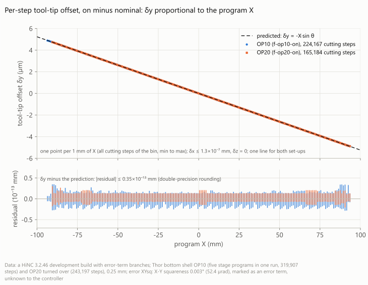
Per-step tool-tip offset (on minus nominal, program coordinates): on the 224,167 cutting steps of OP10 and the 165,184 of OP20, δy lies on −X·sin θ (±4.9 µm where |X| ≤ 93.5 mm), its residual within 3.49 × 10⁻¹⁴ mm (the largest of the three axes is δx's, within 8.33 × 10⁻¹⁴ mm); δx within 1.3 × 10⁻⁷ mm, δz = 0; every step's machine coordinates are the same on and off. The residual axis is symmetric. A HiNC 3.2.46 development build with error-term branches.
- One formula for both set-ups. The pivot lies on the spindle axis both touch-off poses share, so the tip offset of OP10 and of OP20 depends on program X alone and is 0 at x = 0; the program-zero offset is |b| ≤ 2.67 × 10⁻¹⁴ mm.
- A few steps change
IsTouched. On and nominal have the same steps, lines and machine coordinates; only whether a step touches the stock differs: 33 steps int-op10-on(17 fewer touching, 46,498 against 46,515), 268 inf-op10-on, 1,397 inf-op20-onand 1,458 inf-op20-seated. OP20 differs most in T6, the D2 ball on the countersinks (149,270 steps in all): 1,302 off-op20-on's 1,397, and also 1,302 off-op20-seated's 1,458. The stock is not the main cause: the trimmed OP20 on and nominal runs share one block and still differ on 465 steps (444 of them T6), while A and B, with bit-identical tips and only the stock different, differ on 63 (T1 16, T5 47, T6 none). The flips come mostly from the tip offset δ, which makes a grazing step touch the stock or miss it. A cutting step is always taken from the nominal run (dilemma 12). - The residual is a length. The residuals in the table are the length of the three-axis residual vector; per axis, the largest on the cutting steps is δx's 8.33 × 10⁻¹⁴ mm and δy's 3.49 × 10⁻¹⁴ mm, and over every step δx's 1.07 × 10⁻¹³ mm. |b| is a length too.
OP10: one set-up is a shear of ±4.4 µm
How it was measured: the 809,659 vertices of f-op10-on's exported cut, each given its signed distance d
to OP10's nominal cut (positive = material left, blue in the Diff; negative = cut too deep, red).
| Quantity | Measured | Predicted |
|---|---|---|
| Outer long walls' slope (|y| 55.4–55.6, z −34…−20, |x| ≤ 82; 38,988 vertices on each side) | +y −52.34, −y +52.34 µm/m; intercept +0.006 µm | −52.36, +52.36; 0 |
| Inner long walls' slope (|y| 51.9–52.1, z −24…−10, |x| ≤ 80; 38,076 each) | +y +52.34, −y −52.34 µm/m; intercept +0.006 µm | +52.36, −52.36 |
| Outer wall boxes (x 62–82) | +y x+ −3.773, x− +3.773; −y x+ +3.773, x− −3.773 µm | ∓3.77 |
| Inner wall box (+y, x 62–80) | +3.719 µm | +3.72 |
| Wall thickness (outer x+ box plus inner x+ box) | −0.053 µm | −0.05 (the two boxes' x ranges differ by 2 mm) |
| Boss (37.5, 37.5), −y free side | +1.972 µm | +1.96 |
| The +y wall's +x end face | −0.008 µm | 0 (−1.2 × 10⁻⁴) |
| Every vertex, 1st / 99th percentile | −4.30 / +4.25 µm; 47.7 % of the vertices within 0.1 µm | ±4.42 at the ends of the long walls |
The two faces of one wall move the same way as a whole (their normals are opposite, so d takes opposite signs of the same size), and the wall keeps its thickness: no size cut in OP10's one set-up is changed by this error. The end face box reads −0.008 µm; the floor and the tops of the bosses and pads carry no box and show green in the Diff (predicted 0).
OP10 (f-op10-on against nominal, one set-up), isometric, looking over the near long wall into the
cavity, alternating “Error terms on” and “Error terms off” (f-op10-control). With them on, the two
long-wall faces in view (the far wall's inside, the near wall's outside) both run from red at the lower
left end (cut too deep, about −4.4 µm) through green to blue at the upper right end (material left); the
two walls move the same way as a whole, so these two faces take the same colour at the same end; the
floor, the end faces and the tops of the bosses and pads are green. That the two faces of one wall get
opposite colours cannot be seen in this picture; the table above has the values (+y outside x+ −3.773,
inside x+ +3.719 µm), and the wall keeps its thickness. Which end of the picture is x+ was not checked
(the shear pattern looks the same turned 180° about Z), so the caption names positions in the picture
only. The second colour bar at the lower right, “L. 0–1”, has nothing to do with the Diff. Diff colour
scale ±0.005 mm (blue = material left, green = 0, red = cut too deep); 0.25 mm grid; a HiNC 3.2.46
development build with error-term branches.
OP20, the finished part, A: opposite shears, 8.85 µm apart at the ends of the long walls
How it was measured: the 853,997 vertices of f-op20-on's exported cut, against OP20's nominal cut,
whose stock was OP10's nominal cut turned over. Coordinates are OP20's (x unchanged, y′ = −y,
z′ = −z − 40.536).
| Quantity | Measured | Predicted |
|---|---|---|
| The long walls' OP10 band, slope (|y′| 55.4–55.6, z′ −20.5…−7, |x| ≤ 82; 37,620 vertices on each side) | +y′ +52.34, −y′ −52.34 µm/m; intercept +0.006 µm | +52.36, −52.36 |
| The 49° chamfers, slope (within 0.05 mm of the design chamfer, z′ −3.6…−0.5; 15,817 / 15,851 vertices) | +y′ −39.44, −y′ +39.45 µm/m | −39.49, +39.49 (0.7543θ) |
| The seam band's outside, slope (|y′| 55.4–55.6, z′ −5.9…−5.1; 1,065 vertices on each side of x = 0) | the +y′ wall at x > 0 −52.93, at x < 0 +52.93 µm/m: a V, negative at both ends | −θ|x|: ∓52.36 |
| Seam boxes (|x| 62–82) | −3.773 / −3.773 µm | −3.77 / −3.77 |
| The seam's step at z′ −6 (the outside face: the seam band z′ −5.9…−5.1 against the OP10 band z′ −7.0…−6.1) | the +y′ wall's median at x 62–82 7.545 µm; two straight-line fits 8.849 µm apart at x 84.5; 0.000 at the x− end (the −y′ wall the other way round: 8.849 at its x− end) | 2θx: 7.54 at x 72, 8.849 at x 84.5; 0 at the other end |
| The seam band's section (the outside face to the inner ledge at y′ 48.165, |x| 62–76) | the +y′ wall's x+ end −7.225, the −y′ wall's x− end −7.221 µm; the other two ends 0.000 | −2θ|x|: −7.23 at x 69 |
| Long wall's end face (the +y′ wall's +x end, OP10's part) | 0.000 µm | 0 |
| Ø3.3 hole at (37.5, −37.5): +y′ / −y′ / +x side | +1.913 / −1.955 / 0.000 µm | +1.96 / −1.96 / 0 |
| Its boss outside: +y′ free side / +x side | +1.972 / +0.088 µm | +1.96 / 0 |
| The 2.0 mm boss wall (hole wall plus boss face): +y′ side / +x side | +3.885 / +0.088 µm | +3.93 / 0 |
| Countersink at (72.5, 40), −y′ side / pad −y′ free side | −3.041 / −3.686 µm | −3.06 / −3.80 (vertex by vertex in the same boxes −3.054 / −3.735) |
| The 1.2 mm pad wall, −y′ side (hole wall −2.881 plus pad free side −3.686, in the box) | −6.567 µm | −7.59 on the centreline; −6.49 vertex by vertex in the same box |
| Countersink at (−69.5, −40), +y′ side / pad +y′ free side | −2.922 / −3.531 µm | −2.93 / −3.64 (vertex by vertex −2.925 / −3.578) |
| Floor face z′ = 0, the floor's +x end face, centre Ø5.1 | 0.000 µm | 0 |
| Every vertex, 1st / 99th percentile | −4.32 / +4.23 µm |
- The two bands of a long wall lean opposite ways. The OP10 band and the chamfer OP20 cut slope with opposite signs (+52.34 against −39.44 µm/m); the chamfer's slope is smaller because only 0.754 of the 49° face's normal lies along y′.
- The seam takes the deeper cut. The seam band's outside follows OP20's cut at x > 0 and OP10's at x < 0, so it is negative at both ends, a V. At the +y′ wall's x > 0 end, the seam's outside is OP20's cut while the inner ledge behind it is OP10's: the section is 2θ|x| thinner (−7.23 µm measured), and the outside face keeps a 2θx step at z′ = −6 (8.849 µm at x 84.5). At the other end the outside is OP10's cut too: no step, the section unchanged. The seam band's slope reads ±52.93 µm/m, 1.1 % above the predicted 52.36; the band is only 0.8 mm tall, the cause was not followed further, and the seam boxes' medians are as predicted (−3.773).
- Holes against bosses and pads. The holes and countersinks are OP20's cut (−θx), the bosses and pads OP10's (+θx on the finished part), so the wall between them is thicker on one side and thinner on the other. The boss wall at x 37.5 is 3.885 µm thicker on its +y′ side (predicted 3.93) and unchanged on its +x side (0.088). The pad wall at x 72.5 is 6.567 µm thinner on its −y′ side in the box: the box spans x ±0.6 mm and the small hole's and the pad's normals are oblique, so the box median is smaller than the 7.59 on the centreline; the vertex-by-vertex prediction for the same box, −6.49, agrees.
- The pads' free sides read about 0.11 µm shallower than the plan's values (−3.686 against −3.80, −3.531 against −3.64): the plan took the x and the normal at the box centre, and the vertex-by-vertex predictions, −3.735 and −3.578, are only about 0.05 µm (0.049, 0.047) from the measured medians.
OP20's finished part A, the floor face from above (looking along −z′), alternating “Error terms on”
(f-op20-on) and “Error terms off” (f-op20-control). The floor face z′ = 0 and the centre Ø5.1 are
green; the two 49° chamfers at the upper and lower edges run opposite ways (the upper one blue at the left
and red at the right, the lower one the reverse); inside the 7 countersinks and the 4 Ø3.3 holes one side
is blue and the other red, split along y′, the more so the further from the middle; with them off,
everything is green. The two white spots on the floor face are reflections of the canvas lighting,
present in the off frame at the same place, not deviations. The second colour bar at the lower right,
“L. 0–1”, has nothing to do with the Diff. Diff colour scale ±0.005 mm (blue = material left, green = 0,
red = cut too deep); 0.25 mm grid; a HiNC 3.2.46 development build with error-term branches.
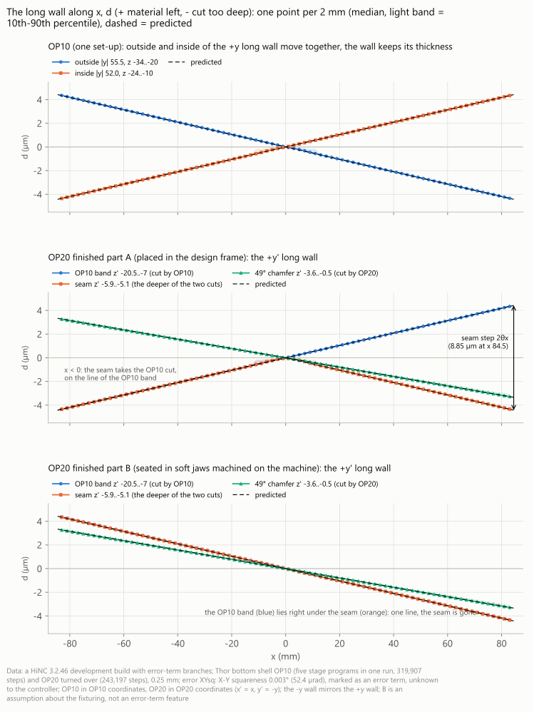
The long wall along x (median and 10th–90th percentile per 2 mm, dashed = predicted). OP10's +y wall outside at −52.34 µm/m, the inside moving the same way (thickness unchanged); OP20 A's +y′ wall: the OP10 band +52.34 µm/m and the chamfer −39.44 µm/m, the seam taking the deeper cut and negative at both ends, and at the x+ end 2θx off the OP10 band at z′ −6 (8.85 µm at x 84.5); B's OP10 band and seam on one line (−52.36 µm/m), the seam gone. B is an assumption about the fixturing, not a feature of the error term. Symmetric deviation axes; 0.25 mm grid; a HiNC 3.2.46 development build with error-term branches.
The round trip of export, turn-over and rebuild
OP20's stock is OP10's exported mesh, turned over and rebuilt. A face OP10 cut should read the same in OP10's Diff and in the finished part's; had the round trip wiped out a difference of a few micrometres, the plan would have made a ×10 version for the pictures.
OP10 box (f-op10-on) |
The same face's box in OP20 (f-op20-on) |
Medians (µm) | Difference |
|---|---|---|---|
op10-wall+y-outer-xpos |
op20-wall-y-op10band-xpos |
−3.7727 / −3.7727 | +0.0000 |
op10-wall+y-outer-xneg |
op20-wall-y-op10band-xneg |
+3.7727 / +3.7727 | +0.0000 |
op10-wall-y-outer-xpos |
op20-wall+y-op10band-xpos |
+3.7727 / +3.7727 | +0.0000 |
op10-wall-y-outer-xneg |
op20-wall+y-op10band-xneg |
−3.7727 / −3.7727 | +0.0000 |
op10-boss-D3.3(37.499,37.499)-y-free |
op20-boss-D3.3(37.499,-37.499)+y-free |
+1.9722 / +1.9722 | +0.0000 |
The round trip loses nothing, no ×10 version was needed, and every number and picture here is the real 0.003°.
OP20, the finished part, B: seated in soft jaws machined on the machine, the long walls' seam is gone
B assumes that OP20's plug and soft jaws were machined on this same machine, so that the part, seated in them, has its long walls along the X travel again: the stock is A's, turned a further −2θ about Z through OP20's program zero. This is an assumption about the fixturing, not a feature of the error term; the programs, the machine and the error are A's, and so are the tool tips and machine coordinates, bit for bit.
| Quantity | Measured | Predicted |
|---|---|---|
| The long walls' OP10 band and seam (z′ −20.5…−5.1; 42,293 vertices on each side) | +y′ −52.36, −y′ +52.36 µm/m; intercept 0.0002 µm | −52.36, +52.36 |
| The seam band's outside, each side of x = 0 | the +y′ wall at x > 0 −52.39, at x < 0 −52.35 µm/m: on one line with the OP10 band | −52.36 |
| Seam boxes against the same side's OP10-band boxes | x+: −3.780 against −3.769 (−0.011); x−: +3.754 against +3.769 (−0.015) µm | a difference of 0 |
| The seam's step at z′ −6 | medians at x 62–82 0.011 / 0.015 µm; extrapolated to the wall end 0.004 / 0.005 µm | 0 |
| The seam band's section | −0.008…+0.008 µm at the four ends (the +y′ wall's x+ 0.000, the −y′ wall's x− −0.008, the other two +0.008 and +0.004) | 0 |
| The +y′ wall's +x end face, OP10's part (x 84.2–84.8, y′ 52.3–55.2, z′ −20.5…−7; 605 vertices) | +5.615 µm | +5.63 (5.48…5.78 across the box, 5.81 at the corner); vertex by vertex +5.618 |
| The same end face, OP20's part (z′ −5.9…−5.1; 33 vertices), and the step between them | +0.015 µm; a step of 5.600 µm | 0; 2θy′ ≈ 5.63 |
| The +y′ wall's −x end face, OP10's part | −5.615 µm (set back) | −5.63 |
| The floor's +x end face | 0.000 µm | 0 |
| Boss: +x side / +y′ free side | −4.046 / −2.078 µm | −3.93 / −1.96 (vertex by vertex −4.029 / −2.090) |
| Ø3.3 hole, +x side | 0.000 µm | 0 |
| Pad free sides at (72.5, 40) / (−69.5, −40) | +3.419 / +3.255 µm (22 vertices each) | +3.80 / +3.64 (vertex by vertex +3.557 / +3.588) |
| The 1.2 mm pad wall: +x side / −y′ side | +4.219 / +0.538 µm | +4.19 on the centreline (|y′| 40) / 0; vertex by vertex +4.54 / +0.80 |
| The 11 boxes OP20 cut (chamfers, holes, countersinks, floor face, floor end face, centre hole), B minus A | 0.0000 µm | 0 |
| Every vertex, 1st / 99th percentile | −5.55 / +4.38 µm |
- The long walls' mismatch is gone, and moves to the faces facing ±x. B's two bands of a long wall run on one line, the seam within 0.011–0.015 µm of the OP10 band. The mismatch between the set-ups becomes 2θy′, along x: on the +y′ wall's +x end face, the part OP10 cut stands out by 5.615 µm, while OP20's T1, finishing the end face back to 84.5 above Z−6, leaves +0.015, a step of 5.600 µm; the same wall's −x end face is set back by −5.615 µm in OP10's part. The −y′ wall is the other way round: its x− end stands out, with the step at z′ −6; on the two set-back ends (the +y′ wall's x−, the −y′ wall's x+) the step is predicted at the lowest level OP10 cut on the end face, z′ −2.3. Apart from the +y′ wall's x+ end, no box measures these steps.
- Bosses and pads change sides. The boss wall's mismatch moves from A's ±y′ sides to the ±x sides (+x −4.046 µm, predicted −3.93); the pads' free sides change sign against A.
- The pads' free sides are the boxes furthest from the plan: +3.419 and +3.255 µm, about 0.38 µm under the plan's +3.80 and +3.64 and 0.14–0.33 µm under the vertex-by-vertex prediction, still within ±1.0. The pads are only 0.98 mm tall, about four rows of the 0.25 mm grid.
- The faces OP20 cut are the same in A and B: the 11 boxes differ by 0.0000 µm. In the captures from above (only faces OP20 cut in view), A and B differ by more than 12 colour levels on only 0.25 % of the part's pixels (on against off at the same camera: 8.3 %); facing the long wall, 84.6 % differ.
One camera (facing the +y′ long wall) alternating “Placed in the design frame (A)” (f-op20-on) and
“Seated in soft jaws machined on the machine (B)” (f-op20-seated, the stock turned a further −2θ about
program zero). In A the OP10 band runs blue at the left to red at the right, the chamfer red to blue, the
seam reddish at both ends; in B the OP10 band turns round (red at the left, blue at the right) and runs
with the chamfer, and the seam merges into the OP10 band's colour (the seam is gone); the chamfer is the
same in A and B. B is an assumption about the fixturing, not a feature of the error term. Diff colour scale
±0.005 mm (blue = material left, green = 0, red = cut too deep); 0.25 mm grid; a HiNC 3.2.46 development
build with error-term branches.
The floor face from above, alternating A (placed in the design frame) and B (seated in soft jaws machined on the machine): everything in view was cut by OP20 (the floor face, the chamfers, the countersinks, the holes, the centre hole), and A and B are nearly the same pixel for pixel (on the part only 0.25 % of the pixels differ by more than 12 colour levels, all at edges; on against off at this camera, 8.3 %): the seating changes only the faces OP10 cut. B is an assumption about the fixturing, not a feature of the error term. Diff colour scale ±0.005 mm (blue = material left, green = 0, red = cut too deep); 0.25 mm grid; a HiNC 3.2.46 development build with error-term branches.
Every box, measured against predicted
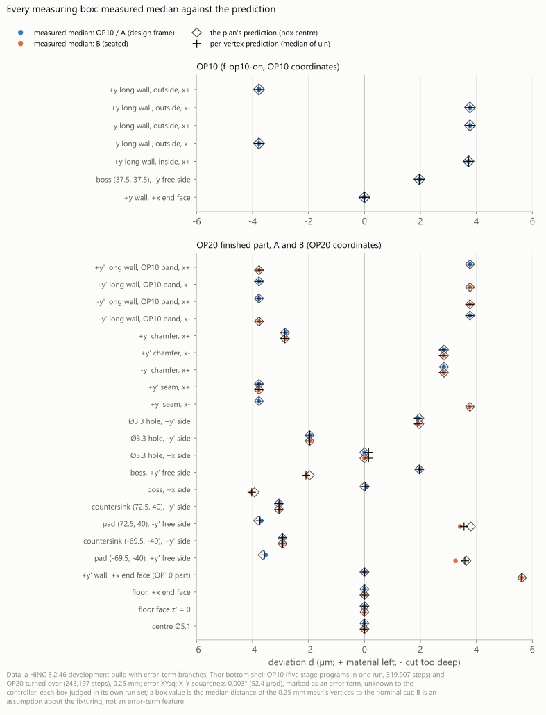
Every measuring box of the plan (7 in OP10, 22 in OP20): the measured median (OP10 and A blue, B orange), the plan's prediction at the box centre (open diamond) and the median of the vertex-by-vertex prediction u·n (cross). B changes only the boxes on faces OP10 cut (long walls, bosses, pads, wall end); the boxes OP20 cut stay as in A. B is an assumption about the fixturing, not a feature of the error term. Symmetric deviation axis, ±6 µm; 0.25 mm grid; a HiNC 3.2.46 development build with error-term branches.
The vertex-by-vertex prediction projects the set-up's displacement u onto the normal n of the nearest triangle of the nominal cut and takes the box median. It uses the 0.25 mm mesh's facet normals, which lean about ±0.03 µm on the chamfers and 0.15 µm on the Ø3.3 hole's +x side (measured 0.000), so it is a reference only; every verdict uses the plan's value at the box centre.
The 7 boxes of OP10 (f-op10-on), µm
| Box | Cut by | Vertices | Measured | The plan's prediction | Vertex by vertex |
|---|---|---|---|---|---|
op10-wall+y-outer-xpos (+y long wall, outside, x+) |
OP10 | 4,617 | −3.773 | −3.77 | −3.770 |
op10-wall+y-outer-xneg (+y long wall, outside, x−) |
OP10 | 4,617 | +3.773 | +3.77 | +3.770 |
op10-wall-y-outer-xpos (−y long wall, outside, x+) |
OP10 | 4,617 | +3.773 | +3.77 | +3.770 |
op10-wall-y-outer-xneg (−y long wall, outside, x−) |
OP10 | 4,617 | −3.773 | −3.77 | −3.770 |
op10-wall+y-inner-xpos (+y long wall, inside, x+) |
OP10 | 4,161 | +3.719 | +3.72 | +3.718 |
op10-boss-D3.3(37.499,37.499)-y-free (boss, −y free side) |
OP10 | 90 | +1.972 | +1.96 | +1.962 |
op10-wallend-x+ (the +y wall's +x end face) |
OP10 | 171 | −0.008 | 0 | +0.001 |
The 22 boxes of OP20, A (f-op20-on) and B (f-op20-seated), µm
| Box | Cut by | Vertices | A measured | A plan | A vertex by vertex | B measured | B plan | B vertex by vertex |
|---|---|---|---|---|---|---|---|---|
op20-wall+y-op10band-xpos (+y′ long wall, OP10 band, x+) |
OP10 | 4,455 | +3.773 | +3.77 | +3.770 | −3.769 | −3.77 | −3.758 |
op20-wall+y-op10band-xneg (+y′ long wall, OP10 band, x−) |
OP10 | 4,455 | −3.773 | −3.77 | −3.770 | +3.769 | +3.77 | +3.770 |
op20-wall-y-op10band-xpos (−y′ long wall, OP10 band, x+) |
OP10 | 4,455 | −3.773 | −3.77 | −3.770 | +3.769 | +3.77 | +3.770 |
op20-wall-y-op10band-xneg (−y′ long wall, OP10 band, x−) |
OP10 | 4,455 | +3.773 | +3.77 | +3.770 | −3.769 | −3.77 | −3.758 |
op20-chamfer+y-xpos (+y′ chamfer, x+) |
OP20 | 1,377 | −2.823 | −2.84 | −2.854 | −2.823 | −2.84 | −2.854 |
op20-chamfer+y-xneg (+y′ chamfer, x−) |
OP20 | 1,377 | +2.835 | +2.84 | +2.807 | +2.835 | +2.84 | +2.807 |
op20-chamfer-y-xpos (−y′ chamfer, x+) |
OP20 | 1,377 | +2.835 | +2.84 | +2.807 | +2.835 | +2.84 | +2.807 |
op20-seam+y-xpos (+y′ seam, x+) |
the deeper cut | 243 | −3.773 | −3.77 | −3.770 | −3.780 | −3.77 | −3.770 |
op20-seam+y-xneg (+y′ seam, x−) |
the deeper cut | 243 | −3.773 | −3.77 | −3.770 | +3.754 | +3.77 | +3.770 |
op20-hole-D3.3(37.499,-37.499)+y (Ø3.3 hole, +y′ side) |
OP20 | 95 | +1.913 | +1.96 | +1.911 | +1.913 | +1.96 | +1.911 |
op20-hole-D3.3(37.499,-37.499)-y (Ø3.3 hole, −y′ side) |
OP20 | 95 | −1.955 | −1.96 | −1.958 | −1.955 | −1.96 | −1.958 |
op20-hole-D3.3(37.499,-37.499)+x (Ø3.3 hole, +x side) |
OP20 | 95 | 0.000 | 0 | +0.148 | 0.000 | 0 | +0.148 |
op20-boss-D3.3(37.499,-37.499)+y-free (boss, +y′ free side) |
OP10 | 85 | +1.972 | +1.96 | +1.962 | −2.078 | −1.96 | −2.090 |
op20-boss-D3.3(37.499,-37.499)+x (boss, +x side) |
OP10 | 85 | +0.088 | 0 | +0.023 | −4.046 | −3.93 | −4.029 |
op20-csink-D2.7(72.504,40.001)-y (countersink at (72.5, 40), −y′ side) |
OP20 | 61 | −3.041 | −3.06 | −3.054 | −3.041 | −3.06 | −3.054 |
op20-pad-D2.7(72.504,40.001)-y-free (pad at (72.5, 40), −y′ free side) |
OP10 | 21 / 22 | −3.686 | −3.80 | −3.735 | +3.419 | +3.80 | +3.557 |
op20-csink-D2.7(-69.496,-39.999)+y (countersink at (−69.5, −40), +y′ side) |
OP20 | 59 | −2.922 | −2.93 | −2.925 | −2.922 | −2.93 | −2.925 |
op20-pad-D2.7(-69.496,-39.999)+y-free (pad at (−69.5, −40), +y′ free side) |
OP10 | 21 / 22 | −3.531 | −3.64 | −3.578 | +3.255 | +3.64 | +3.588 |
op20-wallend-x+ (the +y′ wall's +x end face, OP10's part) |
OP10 | 605 | 0.000 | 0 | +0.002 | +5.615 | +5.63 | +5.618 |
op20-floorend-x+ (the floor's +x end face) |
OP20 | 2,583 | 0.000 | 0 | +0.001 | 0.000 | 0 | +0.001 |
op20-floorface (floor face z′ = 0) |
OP20 | 19,521 | 0.000 | 0 | 0.000 | 0.000 | 0 | 0.000 |
op20-centre-D5.1 (centre Ø5.1) |
OP20 | 1,616 | 0.000 | 0 | 0.000 | 0.000 | 0 | 0.000 |
Each box is judged only in the run set its note names. All 22 boxes of the control run f-op20-control
have medians within ±2.91 × 10⁻⁷ µm.
The tolerance ledger: how far out of square before this enclosure is in trouble
The base case's drawings carry no tolerance block, so its general tolerance is ISO 2768-m. Sizes cut in one set-up only (the 3.5 mm walls below z′ −8, the 2.5 mm groove walls) move both their faces together and do not change; the 2.0 mm floor has its two faces in different set-ups, but both are horizontal, and an X–Y squareness does not move z. What changes is a size whose two faces come from the two set-ups and are not horizontal.
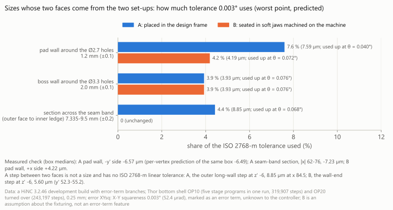
The sizes whose two faces come from the two set-ups: how much of the ISO 2768-m tolerance 0.003° uses at the worst point (predicted). In A the 1.2 mm pad wall 7.6 % (used up at θ = 0.040°), the 2.0 mm boss wall 3.9 %, the section across the seam band 4.4 % (7.335 mm where |x| is up to about 78, about 9.3–9.5 mm at x 80–84.5, both in the ±0.2 class; the worst point at x 84.5); in B the pad wall 4.2 %, the boss wall 3.9 %, the seam-band section unchanged. The steps between two faces (A's seam, B's wall end) are not sizes and are listed as measured. B is an assumption about the fixturing, not a feature of the error term.
| Size | Which set-up cut each face | General tolerance | A, worst point (predicted) | A uses | Used up at θ | B, worst point (predicted) | B uses | Measured check |
|---|---|---|---|---|---|---|---|---|
| The 1.2 mm pad wall outside a Ø2.7 hole | hole OP20, pad OP10 | ±0.1 | 7.59 µm (x 72.504, ±y′ sides) | 7.6 % | A 0.040° (13 times); B 0.072° | 4.19 µm (|y′| 40, ±x sides) | 4.2 % | A, −y′ side in the box −6.57 µm (−6.49 vertex by vertex in the same box); B, +x side +4.22 µm |
| The 2.0 mm boss wall outside a Ø3.3 hole | hole OP20, boss OP10 | ±0.1 | 3.93 µm (x 37.5, ±y′ sides) | 3.9 % | 0.076° | 3.93 µm (|y′| 37.5, ±x sides) | 3.9 % | A, +y′ side +3.88 µm; B, +x side −4.05 µm |
| The section across the seam band, 7.335–9.5 mm (the outside face to the inner ledge, z′ −6…−4.52; 7.335 up to |x| ≈ 78, about 9.3–9.5 at x 80–84.5) | outside OP20, ledge OP10 | ±0.2 | 8.85 µm (x 84.5, in the 9.5 mm stretch; in the 7.335 mm stretch about 8.2 µm at worst) | 4.4 % (the 7.335 mm stretch about 4.1 %) | 0.068° | 0 | 0 | A, |x| 62–76 −7.23 µm (predicted −7.23); B, all four ends within 0.008 µm |
| The steps between faces: A's long-wall outside at z′ −6; B's wall end at z′ −6 | above OP20, below OP10 | not a size | 8.85 µm (x 84.5) | — | — | 5.81 µm (the corner) | — | A 8.849 µm (x 84.5); B 5.600 µm (y′ 52.3–55.2) |
- In A the pad wall uses up its tolerance first. The 1.2 mm wall is predicted 7.59 µm thinner on its centreline at x 72.5, 7.6 % of ±0.1 (6.57 µm measured in its box, 6.49 predicted vertex by vertex in the same box); the machine would have to be 0.040° out of square, 13 times this, to use it up. The plan had put the seam band's wall thickness first, taking the band for a 3.5 mm wall; the inner ledge behind it makes the section 7.335 mm up to |x| ≈ 78 and about 9.3–9.5 mm at x 80–84.5, both in the 6–30 mm class of ±0.2, so its worst, 8.85 µm at x 84.5, is 4.4 % (about 8.2 µm, about 4.1 %, in the 7.335 mm stretch) (dilemma 7).
- The largest mismatch is a step, not a size. A's seam stands 8.849 µm apart at x 84.5, the largest mismatch on the part, but a step between two faces has no size, and ISO 2768-m, the case's general tolerance for lengths and angles, gives it no tolerance. The plan's 8.9 % against ±0.1 does not hold; nor does its ranking of B's wall-end step first (5.81 µm at the corner, 5.8 %, 0.052°), a step against ±0.1 as well. B's first is the pad wall, 4.19 µm predicted, 4.2 % (0.072°). A form tolerance on the drawing would be another ledger, not computed here.
- B: the pad wall moves to its ±x sides and uses 4.2 %; the boss wall 3.9 % as in A; the seam-band section does not change.
- The ±0.2 of the 6–30 mm class is ISO 2768-1's value for class m; the standard's text was not read again for this case, and the base case's report goes only as far as the ±0.1 of 0.5–6 mm.
The controller that knows the error (unmarked, trimmed)
t-op10-unmarked clears XYsq's mark, keeps the switch on and the G54. The machine is still the one
with X and Y 0.003° out of square, and now the controller's model holds the error too. But the program is
plain three-axis G54 / G43 / G81: the machine coordinates come from the program's words, the work
offset and the tool length alone, and the controller does not read the machine chain, so it has nothing
to correct
(what a mark changes).
- Step by step: the ten series keys (Cl, MC, FileNo, LineNo, IsTouched, ToolId) equal the marked
t-op10-on's bit for bit. - The part: the eight
Diff--Statscounts are the same; the vertices of the two exported meshes lie at most 4.97 × 10⁻¹⁰ mm apart (a search value, an upper bound); their distance files against the nominal cut are the same bit for bit.
The whole case was not played unmarked (it has to equal the on run), and there is no unmarked capture, so there is no picture alternating “Controller unaware (marked)” and “Controller aware (unmarked)” (dilemma 10). To cut this part right on the real machine, the machine has to be aligned again; a real controller's squareness compensation table is not simulated (Machine Geometric Error).
The control runs and the extremes of the mesh distance
The noise floor. A control run (switch off, with a Diff) is the nominal run played again: the four
controls' tool tips, machine coordinates and IsTouched equal the nominal runs' bit for bit. 100 % of the
vertices of their exported cuts lie within 0.1 µm (t-op10-control 54,336, t-op20-control 42,706,
f-op10-control 797,258, f-op20-control 842,613 vertices); every vertex of the two whole-case controls
lies within ±5.0 × 10⁻⁷ µm, and the largest box median is 3.4 × 10⁻⁷ µm. The error's effect, ±4.4 µm, is
seven orders of magnitude above the noise floor.
Vertices more than 10 µm off. In each of the three on exports of the whole case, a small share of the vertices lies more than 10 µm from the nominal cut, far beyond any box value. Each was measured again on the server with an exact point-to-triangle distance against the nominal cut:
| Run | Vertices | > 10 µm | Share | Negative / positive | In rows of ≥ 50 vertices | Largest |d| | Every vertex, 1st / 99th percentile |
|---|---|---|---|---|---|---|---|
f-op10-on |
809,659 | 3,303 | 0.41 % | 2,829 / 474 | 86 % (5 rows) | 162.7 µm | −4.30 / +4.25 µm |
f-op20-on (A) |
853,997 | 4,868 | 0.57 % | 4,390 / 478 | 90 % (9 rows) | 176.9 µm | −4.32 / +4.23 µm |
f-op20-seated (B) |
851,743 | 4,466 | 0.52 % | 4,388 / 78 | 97 % (11 rows) | 157.3 µm | −5.55 / +4.38 µm |
f-op10-control, f-op20-control |
797,258, 842,613 | 0 | 0 | — | — | ≤ 5.0 × 10⁻⁷ µm | −4.9 / +4.9 and −4.9 / +4.7 (× 10⁻⁷ µm) |
- All of them are real: the exact distances agree with the search values, and none is an artefact of the search among the 12 nearest triangles.
- Most lie in long rows along sharp edges running in x (86 / 90 / 97 %): the two edges of the groove, the wall top, the line where the inner wall meets the inner ledge, the edge of OP10's lowest pass round the outside. Each row lies on one half of one wall only, the half where the error pushes that face into the material (B: 2 vertices excepted); the longest rows start at |x| = 1 mm, where the error is only 0.05 µm. Most of the rest lie at the wall ends, |x| ≥ 78 (452 of 477, 448 of 489, 82 of 132), and some at corners of the pads, the ledge and the inner wall's steps.
- Their size is not the error's. OP10's 5 rows, 7 of A's 9 and 7 of B's 11 keep one size along their whole length (within 1 µm) and do not change with x, while the error grows from 0.05 µm at x = 1 mm to 4.4 µm at the wall end; the other rows vary along x by 2.7–112 µm (A's row at z′ −8 by 23.6 µm, its row at z′ −37.5 by 105 µm; B's four by 2.7–112 µm).
- The largest is half a cell's diagonal: 176.9 µm is only 0.14 µm above 0.25/√2 = 176.8 µm for a 0.25 mm cell, and no vertex exceeds that by more than 0.2 µm.
- The reading: once an edge has moved a little, the 0.25 mm mesh cuts the facet at that sharp edge from the cell's other corner. This is inferred from where they lie, which half, their equal sizes and the largest value, without reading the mesh code. On that reading they are a property of the 0.25 mm mesh at edges and are not used as cut deviations; every size on this page comes from boxes clear of the edges and from the 1st and 99th percentiles (dilemma 9).
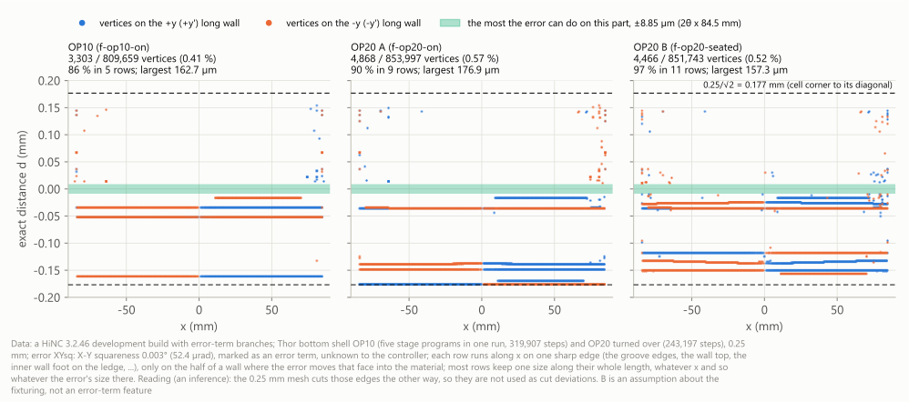
The vertices more than 10 µm from the nominal cut (each measured again on the server with an exact point-to-triangle distance; all are real differences): OP10 3,303 (0.41 %), A 4,868 (0.57 %), B 4,466 (0.52 %), of which 86 / 90 / 97 % lie in 5 / 9 / 11 long rows along sharp edges running in x. Each row lies on one half of a wall, the half where the error moves that face into the material (B: 2 vertices excepted); OP10's 5 rows and 7 rows each in A and B keep one size along their whole length (within 1 µm), whatever the error's size there; the largest, 176.9 µm, is the distance from a 0.25 mm cell's corner to its diagonal, 0.25/√2 = 176.8 µm (0.14 µm more). The reading, an inference: the mesh cuts those edges the other way, so they are not used as cut deviations. B is an assumption about the fixturing, not a feature of the error term. Symmetric distance axis; a HiNC 3.2.46 development build with error-term branches.
The holder in view
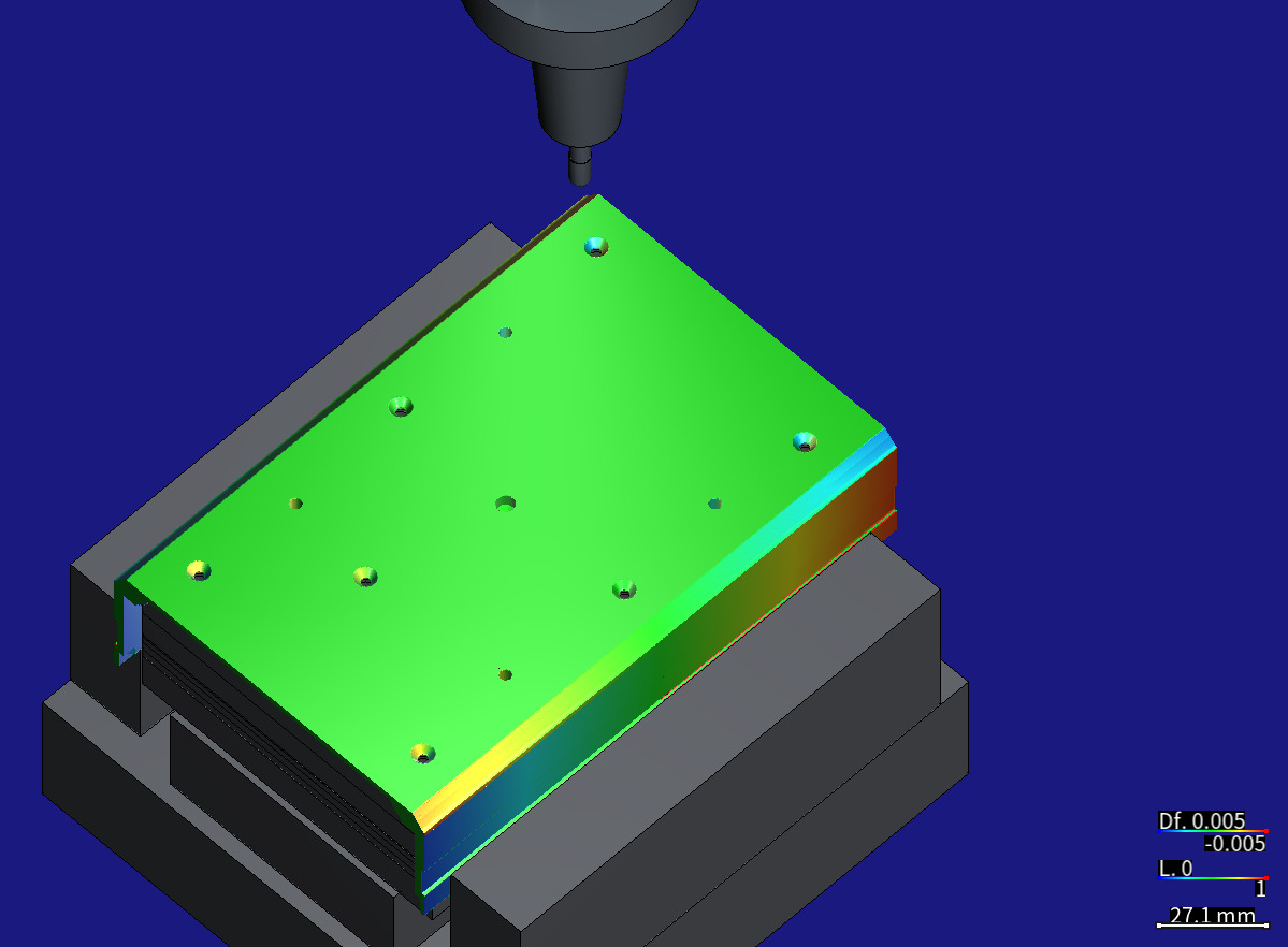
Tool and holder in view: f-op20-on's finished part put back on the canvas with its Diff, then
pose/pose-t5-chamfer.nc played on it: T5 (a D6 ball, 30 mm stick-out) in its BT40 shrink-fit chuck
parked 10 mm above the +y′ chamfer near its x+ end (the tip at X80 Y53.33 Z7.507), spindle stopped; the
part sits on OP20's plug and soft jaws (grey). The parking program cuts nothing. The second colour bar at
the lower right, “L. 0–1”, has nothing to do with the Diff. Diff colour scale ±0.005 mm (blue = material
left, green = 0, red = cut too deep); 0.25 mm grid; a HiNC 3.2.46 development build with error-term
branches.
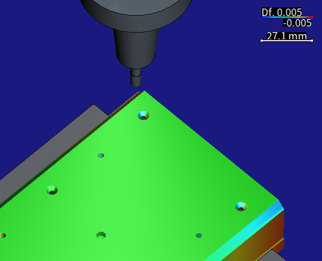
A close-up of the picture above: the tapered nose of the BT40 shrink-fit chuck, the T5 D6 ball, and below them the corner at the +y′ chamfer's x+ end (the +y′ chamfer seen edge-on at this angle); the coloured faces at the lower right are the other side's (−y′) chamfer (blue) and long wall (red) at the x+ end. Diff colour scale ±0.005 mm; 0.25 mm grid; a HiNC 3.2.46 development build with error-term branches.
Diff--Stats of the ten runs with a Diff
| Run | Reported leaves | Surface leaves before comparison | Expanded on demand | New nodes | NaN leaves | Measured wires | Unmeasured wires | Target triangles |
|---|---|---|---|---|---|---|---|---|
| t-op10-on | 122,164 | 51,916 | 22,896 | 93,144 | 84 | 476,375 | 2,129 | 103,488 |
| t-op10-unmarked | 122,164 | 51,916 | 22,896 | 93,144 | 84 | 476,375 | 2,129 | 103,488 |
| t-op10-control | 122,336 | 51,916 | 22,996 | 93,416 | 0 | 478,002 | 1,091 | 103,488 |
| t-op20-on | 152,292 | 42,534 | 35,535 | 145,293 | 0 | 585,995 | 63 | 79,204 |
| t-op20-control | 152,202 | 42,534 | 35,480 | 145,148 | 0 | 585,706 | 24 | 79,204 |
| f-op10-control | 795,156 | 794,646 | 194 | 704 | 10 | 3,146,786 | 10,271 | 1,587,620 |
| f-op10-on | 806,806 | 806,298 | 191 | 699 | 192 | 3,150,711 | 7,243 | 1,587,620 |
| f-op20-control | 874,965 | 840,366 | 11,533 | 46,132 | 443 | 3,474,111 | 675 | 1,674,700 |
| f-op20-on | 886,611 | 852,012 | 11,538 | 46,137 | 405 | 3,466,507 | 2,325 | 1,674,700 |
| f-op20-seated | 884,729 | 844,955 | 13,600 | 53,374 | 0 | 3,468,134 | 3,829 | 1,674,700 |
The nominal runs make no Diff. The NaN leaves are at most 6.9 × 10⁻⁴ of the reported leaves (t-op10-on,
t-op10-unmarked). The whole case's target triangles are fewer than the exported STL's: OP10 1,587,620
against 1,587,794 (174 fewer), OP20 1,674,700 against 1,674,804 (104 fewer); the trimmed counts are the
same as the STL's. Every run with a Diff has one Diff--TargetNotClosed (HiNC reports that the ideal
geometry's mesh is not closed; the ideal geometry is the cut the nominal run exported); the nominal runs
have none.
What the runs cost
All runs used private instances of a HiNC 3.2.46 development build with error-term branches on the shared 32-thread server, the instance restarted before every run. VmHWM is the process's high-water mark of resident memory, recorded in bytes: GB = 10⁹ bytes, GiB = 2³⁰ bytes.
| Run | Grid | Steps | Wall time | VmHWM (GB) | (GiB) | Diff and export |
|---|---|---|---|---|---|---|
| t-op10-nominal | 1 mm | 58,993 | 25.0 s | 0.76 | 0.71 | export |
| t-op10-on | 1 mm | 58,993 | 25.0 s | 0.87 | 0.81 | Diff, export, stock record |
| t-op10-control | 1 mm | 58,993 | 25.0 s | 0.88 | 0.82 | Diff, export, stock record |
| t-op10-unmarked | 1 mm | 58,993 | 25.0 s | 0.81 | 0.75 | Diff, export, stock record |
| t-op20-nominal | 1 mm | 243,197 | 125.1 s | 2.30 | 2.15 | export |
| t-op20-on | 1 mm | 243,197 | 125.1 s | 2.41 | 2.25 | Diff, export, stock record |
| t-op20-control | 1 mm | 243,197 | 125.1 s | 2.42 | 2.25 | Diff, export, stock record |
| f-op10-nominal | 0.25 mm | 319,907 | 545.6 s | 3.96 | 3.69 | export |
| f-op10-control | 0.25 mm | 319,907 | 545.5 s | 4.99 | 4.65 | Diff, export, stock record |
| f-op10-on | 0.25 mm | 319,907 | 530.5 s | 4.98 | 4.64 | Diff, export, stock record |
| f-op20-nominal | 0.25 mm | 243,197 | 1,822.0 s | 20.66 | 19.24 | export |
| f-op20-control | 0.25 mm | 243,197 | 1,832.0 s | 21.26 | 19.80 | Diff, export, stock record |
| f-op20-on | 0.25 mm | 243,197 | 360.4 s | 21.24 | 19.79 | Diff, export, stock record |
| f-op20-seated | 0.25 mm | 243,197 | 450.5 s | 21.25 | 19.79 | Diff, export, stock record |
- Against the plan's estimates.
t-op10: estimated 1–2 minutes and 1–5 GB a run; 25 s and 0.76–0.88 GB, under the estimate.t-op20: estimated 2–4 minutes and 1.5–5 GB; 125 s and 2.30–2.42 GB, within it.f-op10: estimated 4–10 minutes and 3–8 GB; 8.8–9.1 minutes and 3.96–4.99 GB, within it.f-op20: estimated 20–30 minutes and 4–12 GB; 6.0–30.5 minutes and 20.66–21.26 GB. The nominal and control runs went slightly past 30 minutes, the two on runs far under; the memory went over the estimate (dilemma 13).- The whole case was estimated at 1.6–2.5 hours and took 1 h 43 min.
- The stop rules were not reached: the largest VmHWM, 21.26 GB, under 24 GB; the longest OP20 run, 1,832 s, under 60 minutes.
- Two OP20 runs took much longer than the other two. On the same instance build, with the same 243,197 steps and similar peaks, the nominal and control runs took 1,822 and 1,832 s and the on runs A and B 360.4 and 450.5 s, about 4.5 times as long taken together. The slow two are exactly the two whose stock is OP10's nominal cut. These runs did not record how long their stock took to build; on a current build, building that stock from its mesh took about 27 minutes at a 1 mm grid, against under 3.5 minutes for A's stock at 1 mm and at 0.25 mm, about as much as the slow two took longer here, so that build most likely accounts for the difference (an inference). Why that mesh builds so much slower was not looked into. The times are reported as measured; they are neither a cost of the error term nor a performance figure of HiNC.
- In all: the build 2026-10-07 03:38:47–03:38:52; the seven trimmed runs 03:40:36–03:49:21 (525 s, 475.3 s of it playing); the seven whole-case runs, one job, 17:56:16–19:39:33 (6,197 s = 1 h 43 min 17 s, 6,086.5 s of it playing; the 32 s between OP10's last run and OP20's first turned the stocks over and restarted the instance). The job waited for the shared lock before that; the wait is not counted.
- The Diff and the stock record: in OP10 the control and on runs peak 1.02–1.03 GB above the nominal run; in OP20 only 0.58–0.60 GB: all four OP20 peaks lie at 20.66–21.26 GB, and the agent running the case saw them come in the first minutes, while the stock is built from its mesh (the records hold only the peak).
- Not comparable with the base case's cost: the base case accepted its programs with physics on, a reset at every stage and a Diff against the design part.
- The wall time includes the export, the Diff, the stock record and building the stock, and whatever else the server ran at the time.
What it means
For a machining engineer.
- One machine, one 0.003°: within one set-up only the faces facing ±Y lean whole by ±4.4 µm, and wall thickness, groove walls and floor thickness stay as they are; once the part is turned over, the faces the two set-ups made stand twice that apart (8.85 µm at the ends of the long walls), and the thin walls round the holes get thicker on one side and thinner on the other. The programs, the machine coordinates and the touch-off all look right.
- Where the mismatch lands depends on how OP20 holds the part: placed in the design frame, it lands on the long walls' seams and on the ±y sides of the holes; seated in soft jaws or on a plug machined on the same machine, the long walls' seam disappears, and the mismatch moves to the wall ends and the ±x sides of the holes.
- This enclosure does not need a better machine: the tightest size, the 1.2 mm pad wall, is predicted to use 7.6 % of its ±0.1, and the machine would have to be 0.040° out of square to use it up.
- In a plain three-axis program, a controller with calibrated kinematics has nothing to change either (the trimmed unmarked run is bit for bit the marked one); to change the part, the machine has to be aligned again, or the controller's own squareness compensation used, which HiNC does not simulate.
- In HiNC, a constant error measured on a machine can go into the model, and its shape and size on one's own part, across two set-ups, show before the part is cut.
For a teacher or a student.
- Why turning the part over doubles the same error: a shear about Z changes sign on a part turned over about X.
- An X–Y squareness moves only the faces facing ±Y, in proportion to x; a surface keeps only the normal component of the offset (0.754 on the 49° chamfer, 0.806 on the countersink cone); where two cuts meet, the deeper one stays.
- An error has to sit between the two slides to leave a shape error; upstream of X it is only a shift a touch-off takes out. Choosing the pivot is choosing the touch-off point, and one pivot can hold for two set-ups at once.
- Marked and unmarked stand for uncalibrated and calibrated kinematics, and the difference exists only under RTCP, a tilted plane or CL playback.
For someone weighing the approach.
- The build and fourteen plays; the whole case as one job of 1 h 43 min, each OP20 play peaking at about 21 GB.
- The predictions, written before the first play: the tip formula met to 8.36 × 10⁻¹⁴ mm; OP10's 7 boxes and A's and B's 22 each, their measured medians at most 0.39 µm from the plan's values (B's pads), all others within 0.12 µm; the round trip of the turn-over 0.0000 µm.
- What needed saying is written as measured: the plan's tolerance ledger was wrong, the mesh reads long rows along sharp edges, two OP20 runs were slow, and the memory went past the estimate.
Honest limits
- One error only, and a constant one. A real three-axis machine has other squareness errors at the same time (X–Z, Y–Z), angular errors of each axis, and positioning and straightness errors that vary with position. An error term holds only a constant error; errors that vary with position (positioning, straightness, volumetric error tables), backlash, servo mismatch and thermal growth cannot be put in, and neither is a real controller's compensation table simulated (Machine Geometric Error).
- The size and the sign are chosen. 0.003° is a typical value, not a measurement of any machine; every deviation is in proportion to θ. With θ the other way, every deviation changes sign (which end is blue and which red swaps over), at the same size.
- The touch-off is assumed. The pivot on the spindle axis through program zero assumes both set-ups are touched off at program zero. Touched off elsewhere, the part gets one more constant shift, the line of zero deviation moves with it, and the slopes stay.
- B is an assumption about the fixturing. The model only turns the stock by −2θ; how the soft jaws and the plug are machined, the contact errors of seating the part, and clamping deformation are outside it. A real shop's seating may also lie between A and B.
- Geometry only. Physics is off: cutting force, tool deflection, a thin wall pushed away, clamping force and heat are outside this case. The base case recorded the bending of the shell's long cutters on their finishing passes (within 22 µm at the 95th percentile, more at single steps), larger than the ±4.4 µm here; on a real machine the two add up.
- Only the bottom shell. The top cover and the front and back panels are made in two set-ups as well; this case did not run them.
- Reading a 0.25 mm mesh. On sharp edges, 0.41–0.57 % of the vertices read 10–177 µm; exact distances confirm them as real differences between the meshes, and the reading that the mesh cuts an edge the other way is inferred (dilemma 9). The pads are only 0.98 mm tall and the seam band 1.48 mm, a few rows of the grid. The boxes stay clear of edges, and sizes are read as box medians and the 1st and 99th percentiles.
- The vertex-by-vertex prediction is a reference only. It uses the 0.25 mm facet normals of the nominal mesh, off by about ±0.03 µm on the chamfers and 0.15 µm on the Ø3.3 hole's +x side.
- Two predictions were not measured. In A the chamfer's edge at the end where the seam takes OP10's cut (the +y′ chamfer at x < 0, the −y′ chamfer at x > 0) is predicted 2θ|x| shorter (8.85 µm at x 84.5); in B the steps at z′ −2.3 on the two set-back ends. No box measures them.
- The Diff's target has fewer triangles than the STL (174 fewer for OP10, 104 for OP20; the trimmed
ones equal), not looked into; every run with a Diff reports one
Diff--TargetNotClosed. No conclusion depends on it. - The records keep warnings and above only. Messages below were not kept. Among the warnings kept, each of
the four whole-case OP20 runs has one
ToolChange--UnsafePose, a false warning of the build these runs used: that build's step count did not yet include the steps still waiting to be cut, so the steps a tool change checks slid back onto the last cuts before it. The program makes every tool change with the spindle at machine Z0, the tool tip more than 340 mm above the stock. A current build replaying the whole OP20 program, on the nominal run's stock at 1 mm and on A's at 0.25 mm, raises none. - The ±0.2 of the 6–30 mm class was not read again in the standard. It is ISO 2768-1's value for class m; the base case's report goes only as far as the ±0.1 of 0.5–6 mm.
- One picture the plan listed was not taken: A from inside the cavity, isometric. That the bosses, the pads and the holes show the same colour on the same side rests on box values only (dilemma 7).
- The wall times include the export, the Diff, the stock record, building the stock, and any other load on the server at the time.
What a reader can take to their own case
- Put the error on a branch of its own, directly upstream of the axis it belongs to, and for a squareness between two slides, where it really sits between them: upstream of the lower slide it turns both slides together and leaves only a shift a touch-off takes out (Where an Error Term Goes).
- Put a rotation's pivot on the spindle axis at the touch-off pose. The deviation is then zero there, the nominal work offset is the one a touch-off finds, and when two set-ups touch off on the same vertical line, one pivot holds for both (Program Zero Alignment).
- Carry the stock across a turn-over as the cut part, exported and turned with the same matrix the base case uses, and check the round trip on a few boxes before reading the second set-up.
- Expect a machine error to change sign on a part turned over, and the mismatch between the set-ups to double. Where it lands depends on the fixturing: when that is not known, play the seatings that can happen, and say which one is an assumption.
- Read the tolerance on the sizes whose faces come from both set-ups, taking each section from the design model rather than from what the plan assumed; a step between two faces is not a size.
- Make each project's nominal cut the ideal geometry. The Diff then shows the error, not the toolpath's own marks.
- Take the cutting steps from the nominal run, since the error itself changes which steps touch the stock.
- Check extreme mesh distances with exact point-to-triangle distances, and keep judged boxes clear of sharp edges: here rows along the edges read up to 0.177 mm, half a cell's diagonal, while the error is 4.4 µm.
- In a plain three-axis program a mark changes nothing in the cut: every error in the chain is cut into the part; only RTCP, a tilted plane or CL playback let the controller compensate (What a mark changes).
- Budget memory for a stock built from a large mesh: here each OP20 play peaked at about 21 GB, the peak coming, as the agent running the case saw, while its stock of about 1.6 million triangles was built; OP10's plays on a plain block at the same 0.25 mm grid peaked at 3.96–4.99 GB, and the trimmed OP20 runs on a 12-triangle block at 1 mm at 2.30–2.42 GB.
Source and licence
- Source: Antmicro, Enclosure for Antmicro baseboard with NVIDIA Jetson AGX Thor,
https://github.com/antmicro/jetson-agx-thor-baseboard-enclosure (branch
main, read 2026-09-30); the rights holder is Antmicro. Search terms if the link moves:antmicro jetson-agx-thor-baseboard-enclosure,cnc-milled-bottom-shell-al. - Licence: Apache License 2.0. The README states “Copyright (c) 2026 Antmicro” and, under Licensing, “This project is published under the Apache-2.0 license.” The licence gives the material as is, without warranty.
- Attribution, as the base case's source record gives it: “Enclosure design (c) 2026 Antmicro, Apache-2.0, https://github.com/antmicro/jetson-agx-thor-baseboard-enclosure. Machining set-up by Tech Coordinate's agent (changes: stock, fixtures, toolpaths).” The NVIDIA product name is used only to say what the enclosure fits.
- The reference for the error's size: M. Holub, R. Jankovych, J. Vetiska, J. Sramek, P. Blecha, J. Smolik, P. Heinrich, “Experimental Study of the Volumetric Error Effect on the Resulting Working Accuracy—Roundness”, Applied Sciences 10(18), 6233 (2020), https://doi.org/10.3390/app10186233, CC BY 4.0. Only one value is used, read off Fig. 6 (LTc1, the X–Y squareness before compensation, 24.4 µrad); none of the article's figures is reproduced.
- What was used and changed:
- The part models are used unchanged. The base case added the stock, the fixtures (a vice and a tab, a plug and soft jaws), the tools and holders, the two set-ups' toolpaths and programs, and the HiNC projects.
- This case adds the error term
XYsqon the Y axis of the machine chain (an X–Y squareness of 0.003°, a typical value the agent chose, not a measurement of any machine), OP20 stocks turned over from OP10's cut (B's turned a further −2θ, an assumption about the fixturing), and a parking program,pose/pose-t5-chamfer.nc, that cuts nothing. - No third-party picture is reproduced. The pictures are HiNC captures, the charts are drawn from HiNC's per-step results and the exported cut meshes, and the schematic is the agent's own.
- Everything on this page is simulated; no part was cut. This site offers no download; fetch the originals from the source.
See Also
- Jetson AGX Thor Enclosure — how the enclosure's set-ups, the agent's CAM and the programs replayed here were made and accepted
- Jetson AGX Thor Enclosure, Optimized — HiNC's feed optimization on the same case, a separate study
- Building Virtual Machine Tools: Error terms — where an error term may go, what a mark changes, the Enable Error Terms switch, and work offsets on a machine with error terms
- Kinematic Topology: Error-Term Branches — the nominal chain the controller solves, and which errors it can see
- Machining Issues Outside the Model: Machine Geometric Error — the machine errors the model leaves out
- Geometry Validation — the geometry difference, its detection radius and its colour scale
- Program Zero Alignment — P0, and typing in a measured work offset
- The NISTIR 6868 Test Part Cut with the X–Y Squareness a Laser Ball Bar Measured on Its Machine — an X–Y squareness a laser ball bar measured, read off a test part's rows of holes and its slot
- Plunge against Layer Roughing of a Deep Slot on a Z Axis 0.003° Out of Square — the same 0.003°, as a squareness of Z to Y, on a deep slot
- Showcase — the other cases, and how a case page reads