Jetson AGX Thor Enclosure, Optimized: HiNC's Feed Optimization Takes 28 to 52 % off the Long-Cutter Set-ups, Holds the Cover's Finishing Bend within 25 µm, and Takes 37 % off a Grille That Looked at Its Limit
The Jetson AGX Thor enclosure is an open-hardware aluminium housing that an AI agent machined in eight set-ups with toolpaths from its own 2.5-axis CAM, on a BT40 machine with a FANUC αT12/12000i spindle. Three of its programs hold the questions a shop would ask. The first set-ups (OP10) of the bottom shell and of the top cover rough and finish their insides with two Ø12 mm end mills, a 54 mm long-reach cutter and a standard one, under the agent's cautious rules: 0.08 mm per tooth, and half feed on every ramp entry and on the full-width first lap of every level. In their finishing passes the cutters bend past the case's 25 µm limit wherever a pass meets more stock than its allowance, up to 42.6 µm on the shell's walls. And the back panel's first set-up spends 120.5 minutes cutting 26 grille slots with a Ø1.5 mm long-neck cutter whose stress HiNC read, at the case's 0.25 mm grid, right at its target of a third of yield. Here the same agent hands these three programs to HiNC's feed optimization, which rewrites the feed of every line from the loads it reads at each step, and asks three questions: how fast can the Ø12 roughing go under the spindle's real power curve, and is the spindle or the chip the limit; can the finishing be held within 25 µm, and at what cost; and is the grille cutter really at its limit?
On HiNC 3.2.45 the bottom shell's OP10 came down from 37.7 to 29.2 simulated minutes with every finishing line held at its programmed chip (V1), and to 27.2 minutes with the finishing also steered by its measured bend (V2); the cover's OP10 from 39.6 to 21.4 and 19.0 minutes; and the grille stage from 120.5 to 75.5 minutes (V3): 76.1 minutes off the three programs, −38.5 %. The Ø12 roughing ran at the ceiling the agent allowed, 1.5 times the programmed chip, on 98.4 and 99.6 % of its cutting steps. At 8,000 min⁻¹ steady roughing at that chip reads only a third of the spindle's short-term rating; only the full-width cut that opens each level reaches the 0.667 target, and there the programmed feed had asked 0.788 of the short-term and 1.01 of the continuous rating, which the optimizer brought under the target. The cover gained most because 72 % of its roughing time was the CAM's half-feed laps, which the optimizer runs at three times their feed.
The finishing is where the agent protected the part. V1 holds every finishing line at its own programmed chip, so the finishing cuts as programmed. V2 adds a target force — 25 µm divided by each cutter's compliance — and, because that target did not act on the steps that change height, a feed ceiling for every finishing line drawn from that line's bend in V1. V2 met the 25 µm on the cover (36.5 → 24.2 µm) and missed it on the shell by one wall step at 26.7 µm and 12 floor steps up to 26.5 µm, while running faster than V1. The grille was not at its limit: the 0.25 mm grid over-reads the stress of a 0.3 mm layer, and at 0.125 mm 99 % of the grille cutter's steps reached the programmed chip. Every optimized program replayed to its last line with no collision, stroke or rapid-cut alarm and left the same part. Everything here is simulated: no part was cut, and the times are HiNC's ideal-feed estimates.
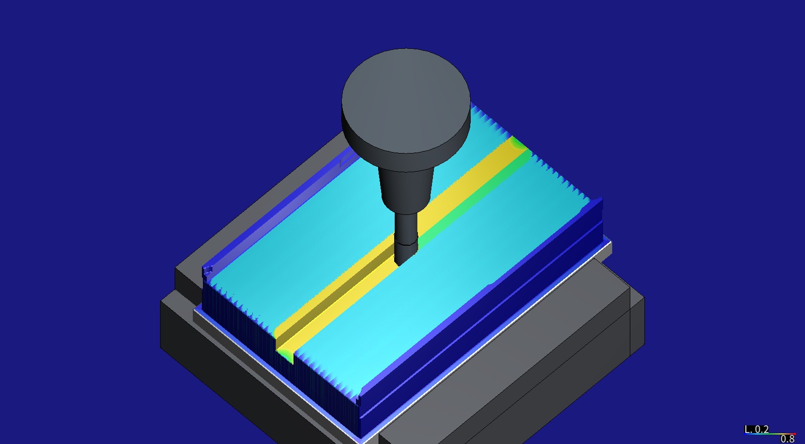
The bottom shell's cavity roughing at the level at Z −19.2 after HiNC's optimization (V1), the Ø12 mm long-reach cutter 54 mm out of its shrink-fit chuck. The faces it cut are coloured by the spindle power ratio of the step that cut them, 0.2 (blue) to 0.8 (red): the band where the level opens with a full-width cut reads the 0.667 target (yellow), the rest of the floor about a third (cyan), at 1.5 times the programmed chip. The same view before the optimization is further down. Captured on HiNC 3.2.45.
| Measured on HiNC 3.2.45 | Source programs | Optimized, replayed | Change |
|---|---|---|---|
| Bottom shell OP10, simulated machining time | 37.7 min | V1 29.2 min / V2 27.2 min | −22.5 % / −27.9 % |
| Top cover OP10 | 39.6 min | V1 21.4 min / V2 19.0 min | −46.0 % / −52.0 % |
| Back panel OP10, the Ø1.5 mm grille stage | 120.5 min | V3 75.5 min | −37.3 % |
| The three programs (V2 and V3) | 197.9 min | 121.7 min | −76.1 min (−38.5 %): 60.5 min cutting, 15.6 min feed through air |
| Ø12 mm roughing, shell / cover | 1,235.7 / 1,726.0 s | 720.4 / 627.2 s | −41.7 % / −63.7 %, at the 0.12 mm ceiling on 98.4 / 99.6 % of the cutting steps |
| Largest spindle power ratio in roughing, shell / cover (target 0.667 of the short-term rating) | 0.788 / 0.463 | 0.664 / 0.665 | the shell's 2,076 steps over the target → 0 |
| Largest continuous power ratio in roughing, shell (reported only) | 1.010 | 0.850 | |
| Finishing XY tip deflection, largest, walls (the case's B1: 25 µm), shell / cover | 42.6 / 36.5 µm | V1 42.6 / 36.5 µm; V2 26.7 / 24.2 µm | V2: cover met, shell 1 wall step and 12 floor steps over |
| Grille cutter's stress ratio, 99th percentile / largest (target 0.333) | 0.282 / 0.338 | 0.331 / 0.333 | 99.2 % of the cutting steps at the programmed chip |
| Grille cutter's XY tip deflection, 99th percentile (the case's B2: 95th percentile ≤ 100 µm) | 49.0 µm | 57.6 µm | B2 met |
| Shape: the agent's z-map, HiNC's exported part, the optimized files | — | — | every node alike within 1 µm but one tie on a wall; volumes within 0.001 %; 71 points of the cover's files up to 5.3 µm off their line |
| Replay messages: collision / stroke / rapid cut | 0 | 0 | one Script-Compile--Error per line that carries an embedded setting and the optimizer's source note (dilemma 7) |
| Run cost on a shared 32-thread server: optimization play / replay | — | 8.5–12.5 min, 19–57 GiB / 3.5–7.7 min, 2–4 GiB | about 105 min of server time with the trials |
The case
The enclosure's own case page tells how the agent planned two set-ups for each of Antmicro's four parts, wrote its own CAM, chose fourteen tools and their holders and played all eight programs through an acceptance; this page starts where that one ends. What the agent was given:
- Three accepted programs (times from this study's plays on HiNC 3.2.45, measured):
- the bottom shell's OP10, 37.7 min: the top faced, the outside profile roughed and finished, the outer groove with a T-slot cutter, the 38.5 mm deep cavity roughed level by level with the walls finished after each, the floor finished, the corners and the gap between the pads cleaned with a Ø6 and a Ø4;
- the top cover's OP10, 39.6 min: the pocket on the underside, the flanges inside and out, the narrow bands beside the flanges cut from outside the outline, eight Ø3.3 holes;
- the back panel's OP10 grille stage, 120.5 min: 26 straight 2.0 mm slots 40–48 mm long through the 1.5 mm web, each in six layers of 0.3 mm, with a Ø1.5 two-flute long-neck end mill.
- The cutters (read from the case): T1, a Ø12 three-flute long-reach aluminium end mill (RobbJack MFMHV-303-12: 19.03 mm flutes, neck Ø11.4 to 54 mm), 54 mm out of a shrink-fit chuck, in the shell; T10, a standard Ø12 three-flute end mill, 32 mm out, in the cover; both at 8,000 min⁻¹. The rest cutters T2 (Ø6 long-reach), T3 (Ø4) and T11 (Ø6); T4, a Ø20 × 5 T-slot cutter; T8, a Ø3.3 drill; and T12, the Ø1.5 grille cutter, 14 mm out, at 12,000 min⁻¹.
- The CAM's feed rules (read from the agent's CAM): the Ø12 cuts at F1920 (0.08 mm per tooth), plunges at F800, ramps in at half feed and runs the rest of each level's full-width first lap at half feed too (F960), links across a full slot at 40 % (F768); a finishing pass ramps in and runs its first lap at F720 (0.03 mm per tooth), then runs the same lap again at F1440 (0.06 mm); the grille cutter ramps in and cuts each layer's first lap, a full slot, at F180, runs a second lap at F360 (0.015 mm per tooth) and plunges at F150.
- The case's criteria for these cutters: B1, the long cutters' XY tip deflection on every finishing step at most 25 µm, a quarter of the ±0.1 mm general tolerance — the one criterion the case's acceptance missed; B2, roughing deflection at the 95th percentile at most 100 µm; spindle power and tool stress below 1.
- The case's set-up: Al 6061-T6; a generic BT40 three-axis machine with 25.4 m/min rapids; the FANUC αT12/12000i spindle HiNC ships, 15 kW on its short-term curve and 12 kW continuous from 1,500 to 6,000 min⁻¹, falling to 5.5 and 3.7 kW at 12,000, so 11.8 and 9.2 kW at the Ø12's 8,000 min⁻¹ (read).
- The request: showcases of HiNC's NC optimization built on existing cases, asked for by HiNC's product owner.
What nothing states:
- How far the Ø12 chip may go. The programmed 0.08 mm per tooth is the agent's; RobbJack's speeds and feeds for the MFMHV-303-12 give 0.1524 mm for roughing and 0.0762 mm for finishing (2024 aluminium, full slot, rigid holding).
- How to hold a deflection limit. HiNC's optimizer holds spindle power, spindle torque, tool stress, a target force and the feed limits; it has no built-in deflection criterion, so B1 has to be carried by another criterion.
- Whether the grid reads the grille's thin layers truly. The grille cutter takes 0.3 mm a layer; the case's grid is 0.25 mm.
Every number on this page comes from this study's plays on HiNC 3.2.45: the optimization play of each source program is also its baseline, so each “before” was measured beside its “after”.
What the agent built
Each value is marked read (from the programs, the case or the catalogue), derived (computed from them), chosen (the agent's choice), default (HiNC's default, kept) or measured (in a play on HiNC 3.2.45).
A variant is one optimization play — HiNC plays the source program with an NC Optimization Config command before it and writes the optimized file after it — and one replay of the optimized file on the same project, stock and grid. Each program played whole in one run.
| Play | On | Grid | What it answers |
|---|---|---|---|
| Trials | trimmed windows of the shell's and the cover's OP10 on 25.5 mm of stock at their +X end, with the V1 and the V2 settings; the back panel's first grille slot, six layers, at three grids | 0.25 mm; 0.25, 0.125, 0.0625 mm | does the optimizer change the feeds in these programs, do the embedded settings land on the right lines, does the replay run clean, what do the plays cost, which grid for V3 |
| V1 | the shell's and the cover's OP10 | 0.25 mm | the Ø12 roughing up to its per-tooth ceiling within the spindle's targets; finishing and rest passes held at their programmed chip |
| V2 | the same | 0.25 mm | V1 plus, on the Ø12 finishing, a target force and a ceiling per line from V1's measured bend: does B1 hold, at what time |
| V3 | the back panel OP10's whole grille stage (source lines 2,294–14,693), on a block of stock over the grille, X −47 to 47, Y −26 to 26, Z −16.5 to −8.0 | 0.125 mm | the grille cutter with its programmed chip as the ceiling |
Each tool's optimization limits, sent whole through PUT api/Cutter/{id}/opt-limit before every
optimization play and read back into the run record: yield safety factor 3 (the stress held to a third of
yield), the minimum-chip-thickness and relief-angle limits on, no minimum feed per tooth — all default —
and a feed-per-tooth ceiling:
| Tool | Programmed feed per tooth — derived (F ÷ speed ÷ flutes) | Ceiling | Source |
|---|---|---|---|
| T1 Ø12 long-reach, T10 Ø12; 3 flutes, 8,000 min⁻¹ | roughing 0.08 mm (F1920), half-feed laps 0.04 (F960); finishing 0.06 (F1440) and 0.03 (F720); plunges 0.033 (F800) | 0.12 mm (F2880) on the roughing | chosen: 1.5 times the programmed roughing chip, under the catalogue's 0.1524 mm roughing value |
| T2 Ø6 long-reach, T3 Ø4, T11 Ø6 (rest cutters) | 0.03, 0.025, 0.04 mm | every line its own programmed chip | chosen: held (below) |
| T12 Ø1.5 long-neck; 2 flutes, 12,000 min⁻¹ | 0.015 mm (F360); first laps and ramps 0.0075 (F180); plunges 0.00625 (F150) | 0.015 mm (F360) | chosen: the programmed chip, not enlarged — catalogues run a long-neck cutter this slender at reduced feed and depth, and in a full slot at F360 it already reads a stress ratio of about 0.30, near the 0.333 target (0.304 at the median on the first slot, optimized and replayed at 0.0625 mm) |
| T4 T-slot cutter | 0.03 mm | optimization off | chosen: it cuts an undercut that the agent's own z-map check cannot see |
| T7–T9 drills | 0.06–0.10 mm per revolution | — | canned cycles (G81), which the optimizer does not change |
The NC Optimization Config before every program, every key written and read back:
| Setting | Value | Source |
|---|---|---|
| Feed optimization, re-interpolation | on | default |
| Max / min feed per tooth | none / 0 | the tools' limits carry the ceiling; the embedded settings lower it where needed |
| Min feedrate | 100 mm/min | chosen: under the lowest programmed cutting feed (the grille's F150 plunges); the default 1 mm/min would let one phantom reading stall a stretch at almost nothing |
| Max feedrate | 10,000 mm/min | chosen: a cautious cutting-feed ceiling for a BT40 machining centre with 25.4 m/min rapids |
| Rapid Feed — the air feed, for lines with no cutting within the extended distances | 10,000 mm/min, set again per segment | derived: the air-feed rule below |
| Max acceleration | 1,000 mm/s² | chosen: the default 10 mm/s² would spread every change of feed over hundreds of millimetres |
| Spindle power and torque safety factors | 1.5: the target is 67 % of the short-term rating | default |
| Yielding and thermal-yield safety factors of the command | 0, 0: the tools' own factor 3 holds | default |
| Preferred force (the target cutting force) | none at the program level; set on V2's finishing lines | V2 (below) |
| Extended pre and post distance | 2 mm and 2 mm | default |
| Feedrate assignment ratio | 0.01 | default |
| Lower limit as a share of the source feedrate | off | default: these programs have never run in production |
| Forward, side and depth compensation; depth splitting | off | chosen: compensation is not part of this study; with depth splitting off, a step the target force pins at the minimum is logged at the minimum |
| Omit leading zero | off | chosen: the agent's checks read every number of the output |
Settings embedded line by line. Each line belongs to the innermost operation that contains it in the
case's own list of operations. Where the class of pass or the tool changes, a script comment (@@…) at
the end of the first moving line sets the new values from that move on, as
Settings Embedded in NC Code describes; on the
finishing and rest lines a comment also goes wherever a line's own setting differs from the one in force.
Nothing else changes: the agent's check confirms that removing the added comments gives the source back
character for character. V1's programs carry 494 (shell) and 201 (cover) such comments, V2's 619 and 245,
V3's one.
| Class of pass | Tools | V1 | V2 | V3 |
|---|---|---|---|---|
| Roughing: facing, outside profile, cavity, with their plunges, ramps and links | T1, T10 | the tool's 0.12 mm ceiling; air feed 10,000 | as V1 | — |
| Wall and floor finishing | T1, T10 | every line its own programmed chip; air feed its own feed | every line's ceiling from V1's bend (below); air feed its own feed; the target force | — |
| Rest machining | T2, T3, T11 | every line its own programmed chip and feed | as V1 | — |
| Grille | T12 | — | — | the tool's 0.015 mm ceiling; air feed 1,010 |
V2's target force = 25 µm ÷ the cutter's compliance, derived: the 95th percentile, over the finishing cutting steps of V1's optimization play with a force over 1 N, of XY tip deflection ÷ the largest cutting force. T1: 0.1207 µm/N → 207.1 N; T10: 0.0950 µm/N → 263.1 N. At that force 95 % of the steps stay within 25 µm. Deflection is HiNC's tool-beam model; the target holds the model's deflection, not a measured one.
V2's line ceilings, derived (dilemma 2 tells why): for each finishing source line, D is the largest XY tip deflection on its cutting steps in V1's optimization play and fz₀ its programmed chip. If D ≤ 25 µm the line's ceiling is min(0.076, fz₀ × (25 ÷ D)²); if D > 25 µm it is max(0.0042, fz₀ × (25 ÷ D)^3.7); each is rounded down to a ladder of 23 values from 0.0042 mm (100 mm/min, the minimum feed) to 0.076 mm, RobbJack's finishing chip for the MFMHV-303-12 (at a 2.4 mm width of cut; the finishing here takes 0.3 mm). The exponents come from the trials: HiNC's force follows the chip as fz^n with n between 0.27 and 0.50, and raising a line uses the steep end (n = 0.5, exponent 2), slowing it the flat end (n = 0.27, exponent 1 ÷ 0.27 = 3.7), both on the cautious side. The target force still applies on every line: it holds where it acts, and the line ceilings make sure that where it does not act no line is sped up past what its own bend allows and the lines over 25 µm are slowed in advance.
The air feed, derived by a rule of the plan. The optimizer sends a step at the air feed when nothing within the 2 mm before and after it touches the stock, so a sliver the grid does not hold — thinner than a cell, or left on a wall where the finishing cutter was pushed away — is cut at that feed. Each tool's air feed is the feed at which a sliver as thick as that tool's 99th-percentile XY tip deflection in the baseline cuts no thicker a chip than the tool's ceiling does in its own cut: with h = fz × sin φ and cos φ = 1 − 2 × radial depth ÷ diameter, F = h at the ceiling ÷ sin φ of the sliver × flutes × speed, kept between the programmed feed and 10,000 mm/min. T1 and T10 come out above 25,000 mm/min and are held at 10,000; T12, in a full slot with a 49.0 µm sliver at 0.125 mm, at 1,010 mm/min. On the finishing and rest lines the air feed is the line's own feed.
Grids, chosen: 0.25 mm for the Ø12 programs, the acceptance's grid: on the X-end windows the finishing deflection, force and compliance read within 8 % at 0.25 and 0.125 mm (cover 33.3 and 33.5 µm, shell 21.9 and 20.4 µm), and 0.125 mm would cost eight times the cells. The grille at 0.125 mm by a rule written before the trials (dilemma 3). Every replay at its optimization play's grid.
Not optimized: rapids, tool changes and their G43 / G49 lines, G91 G28, M codes and the drills'
G81 cycles, which the optimizer does not change; the T-slot cutter (71 s, 3 % of the shell's OP10); the
rest cutters, held at their programmed chip because they cut the last of the R3 corners, where HiNC can
over-read a small cutter's load; the four OP20 set-ups, whose stock is the OP10 part exported from HiNC as
a mesh of up to 1.6 million triangles; and the front panel's grille, which was not played, so no time is
claimed for it.
How the agent managed the work
- Criteria and settings first. The plan — three questions, three variants, every setting with its source, ten criteria and the rule for V3's grid — was committed before the first optimization play, trials included. What the trials changed was written beside the plan as an amendment and committed before the first whole-program play; the results were added after it. The plan's text and the criteria were never rewritten.
- Small before large. Trials on the X-end windows of both Ø12 programs and on the first grille slot at three grids checked the whole chain — optimize, replay, check that the feeds really changed, that every point of the optimized file lies on its source line and that the replay runs every line clean — before any whole program.
- One heavy play at a time. A private copy of HiNC 3.2.45 ran on a 32-thread server shared with live services and other agents' studies. Every heavy play queued on a lock shared with those studies, waited for at least 40 GB of free memory, ran on a freshly restarted instance with the project reloaded from its file, and was looked at read-only every three minutes: the alarms, the tool and line, the share of steps in contact, the loads.
- Settings read back. Each tool's limits and every option were read back after each play and kept with its results, beside the messages, the server time and the memory.
- The study changed hands once. The first agent stopped after the trials. The agent that took over compared the plan on the server with the committed one — they differed only in line endings, so no play had run under an uncommitted change — and committed the amendment and the trial results before the first whole-program play.
- Where a person stepped in. HiNC's product owner asked for NC-optimization showcases built on existing cases; the variants, settings and criteria are the agent's.
The criteria as written before the first optimization play. A cutting step is a step in contact that removes more than 0.01 mm³/s:
| # | Criterion |
|---|---|
| O1 | Every optimized program replays to its last line with no new alarm: the lines run equal the file's; no collision and no stroke alarm; no more rapid cuts than the optimization play at the same grid; no warning or error the optimization play lacks. Every optimization play reaches Optimization Feedrate built. and Total 1 files optimized., with no licence refusal and no StepFailed |
| O2 | The governing loads within target: for each optimized tool, at least 99 % of the replay's cutting steps at or under 0.667 × 1.02 of the short-term power and torque ratings and 0.333 × 1.02 of yield; in V2 at least 99 % of the finishing steps at or under the target force × 1.02. Steps written at the minimum may stay above a target and are listed apart |
| O3 | The shape does not change: (a) every point of the optimized file on its source line within 1 µm; (b) the agent's own z-map (0.1 mm, the grille 0.05 mm) after the optimized program the same as after the source on 99.9 % of its nodes within 1 µm; (c) HiNC's exported parts within 0.1 % in volume |
| O4 | The time, predicted: V1 shell −12 to −25 %, cover −15 to −30 %; V2 no slower than V1; V3 −30 to −55 %. The measured time is reported whatever it is, and a miss is explained from the optimizer's log |
| O5 | Finishing deflection: V1, the p99 and the largest XY tip deflection of every Ø12 finishing class no higher than the baseline's × 1.02; V2 (B1), the largest on finishing steps not at the minimum at most 25 µm × 1.02, those at the minimum listed apart; V3, the grille cutter's p95 at most 100 µm (B2), its p99 and largest against the baseline |
| O6 | The air feed never lands on stock: the agent walks every optimized program in play order over its own z-map; every move that removes more than 0.01 mm³ at a feed above its line's ceiling × 1.02 is listed with its line, feed, volume and depth |
| O7 | The output really is optimized: each optimized file differs from its source; the rewrite reports no error; the optimizer's messages counted; lines, F words and their range, source notes and the embedded settings carried through |
| O8 | The CAM's hand-written feed rules against the optimizer, reported and not judged: plunges, ramps, the half-feed laps, the links, the grille's two laps — the optimized time-weighted median feed and the share of time faster or slower |
| O9 | What set the feed, reported: for every cutting step, the criterion of the per-step log that allowed the lowest feed per tooth. Predicted: V1 roughing at least 80 % at the ceiling, the full-width cuts set by the spindle power; V2 finishing mostly at 0.076, the cover's X end by the target force; V3 mostly at the ceiling |
| O10 | Every tool cuts: in a whole-program run each tool's steps in contact of the same order (±10 %) as in the case's acceptance, which ran one tool per run, and no tool at zero |
The dilemmas
Each is told as its situation, the risk had it been missed, how it was noticed, the resolution, and the evidence that the resolution held.
1. Two programmed chips in one finishing pass
- Situation. The plan held the Ø12 finishing at its programmed chip with one ceiling per segment, 0.06 mm (F1440). But the CAM enters each finishing level by ramping in and running the rest of that first lap at half feed, F720 (0.03 mm per tooth), and then runs the same lap again at F1440. The shell's program has 7,069 finishing lines at F720 (1,058 of them ramps) and 6,517 at F1440; the cover's 1,509 (681) and 1,998.
- Risk. A segment ceiling of 0.06 mm doubles the half-feed lap — the lap that takes the 0.3 mm allowance — so the finishing bends more, on the very criterion the case already misses.
- How noticed. The cover's X-end trial: its finishing deflection rose from a 99th percentile of 33.3 and a largest step of 36.5 µm to 41.7 and 43.6 µm.
- Resolution. Every finishing and rest line is held at its own programmed chip: a comment at the end of the line sets the ceiling to that line's F ÷ (speed × flutes) and the air feed to its own feed, written only where it differs from the setting in force. Those lines can be slowed by a load, never sped up. The rest cutters' plunges and ramps, which the plan had allowed up to their programmed chip, are held the same way: the half-feed lap they belong to is a full-width cut, not only its entry.
- Evidence. In V1 the finishing times barely move (shell walls 271.2 → 271.5 s, floors 581.4 → 586.6 s; cover 155.7 → 156.3 and 455.5 → 459.4 s) and their deflection is the source program's (the B1 table under Results and benefits).
2. A target force that does not act on ramps
- Situation. V2 was to carry B1 as a target force, 25 µm ÷ compliance, with the finishing ceiling raised to the catalogue's finishing chip, 0.076 mm.
- Risk. The raised ceiling speeds every finishing line up; wherever the target force does not hold, the finishing bends more, and V2 makes B1 worse.
- How noticed. In the cover's X-end trial with the V2 settings (a 293.7 N target from the window's compliance) the agent compared every finishing step's force with the optimizer's per-step log. Of the 93 steps at a constant height over the target, the target-force criterion lowered 69; of the 92 steps whose height changes — the ramp entries — it lowered none, so they ran at 0.076 mm and bent up to 44.4 µm. The other criteria do act on steps that change height: in the cover's V1 trial the spindle power set 29 finishing steps on ramps and the stress 2, and in the grille trial at 0.25 mm the stress set 96. The 24 level steps the target force missed lie on one stretch, the lap that follows a ramp on the same level, at Z −13.4. And the largest B1 readings sit on exactly such laps: the cover's outside-profile finish is a ramp, the shell's deepest inner wall the full-feed lap right after one. A second finding ruled out a stronger target: HiNC's force follows the chip only weakly. On pairs of steps at the same cutter location in a source and a replay, the force goes as fz^n with n 0.27 at the 10th percentile, 0.31–0.33 at the median and 0.40–0.50 at the 90th; cutting the cover's chip from 0.03 to 0.0043 mm took its median force only from 346 to 160 N.
- Resolution. V2 keeps the target force where it acts and adds a ceiling for every finishing line from that line's bend in V1 (the formula under What the agent built): no line is sped up past what its own bend allows, and the lines over 25 µm are slowed in advance, ramps included. Of the shell's 7,392 finishing lines with cutting steps, 7,195 were raised, 133 slowed and 64 held; of the cover's 2,395, 2,351 raised, 42 slowed and 2 held.
- Evidence. B1 met on the cover, its walls 36.5 → 24.2 µm, with V2 faster than V1 on both parts; dilemmas 5 and 6 tell where it did not hold.
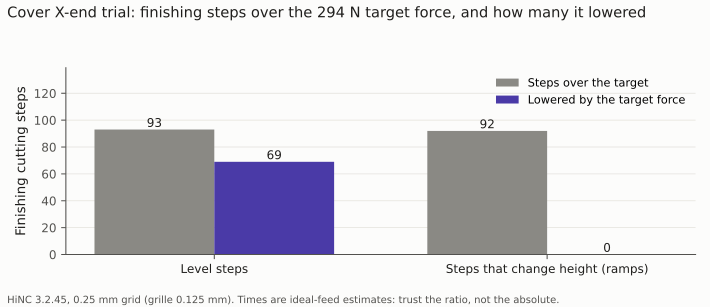
The trial that changed V2: the target force lowered most of the level steps over it and none of the steps on ramps.
| Trial pairs of steps at the same cutter location | Pairs | Feed per tooth, median: source → replay | Force, median | n in F ∝ fz^n: 10th / 50th / 90th percentile |
|---|---|---|---|---|
| Cover X-end, V2 settings | 602 (334 over 250 N) | 0.03 → 0.0043 mm | 345.6 → 160.0 N | 0.27 / 0.326 / 0.452 (over 250 N: 0.27 / 0.309 / 0.435) |
| Cover X-end, V1 settings | 517 (68 over 250 N) | 0.03 → 0.06 mm | 71.2 → 89.1 N | 0.296 / 0.326 / 0.40 (over 250 N: 0.363 / 0.401 / 0.45) |
| Shell X-end, V2 settings | 264 | 0.06 → 0.076 mm | 86.6 → 97.4 N | 0.308 / 0.332 / 0.50 |
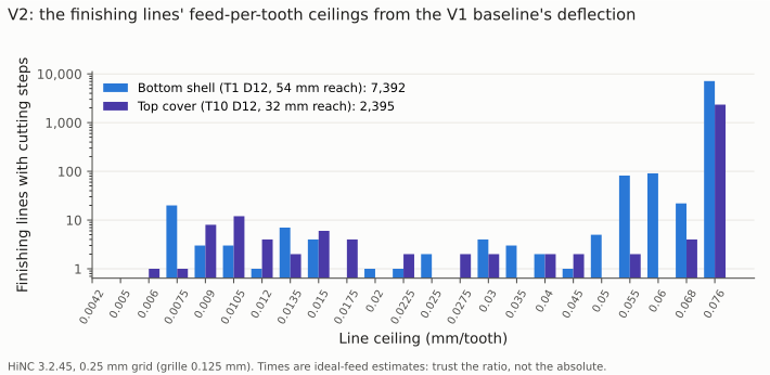
V2's line ceilings: almost every finishing line rises to the catalogue's 0.076 mm; the few that bent over 25 µm in V1 are cut back, the worst on the shell to an eighth of its programmed chip and on the cover to a fifth.
3. A grille that only looked at its limit
- Situation. The grille cutter takes 0.3 mm a layer. At the case's 0.25 mm grid HiNC read the stress of the first slot's half-feed passes, the F180 first laps and ramps, at 0.335 at the 95th percentile and 0.436 at most, against a target of 0.333.
- Risk. Concluding that the grille cannot be sped up — or letting the optimizer slow a third of its steps on a tail that belongs to the grid, and drag the 2 mm before and after each of them down too.
- How noticed. Before the trials the agent played the first slot's six layers at three grids: on those half-feed passes the median stress reads the same at every grid, 0.25 to 0.26, but at 0.25 mm the tail stands 26 % (99th percentile) to 42 % (largest) above the 0.0625 mm one.
- Resolution. A rule written into the plan before the trials: V3 at 0.125 mm if the 0.125 mm window's optimized time lies within 3 % of the 0.0625 mm one and the 0.125 mm optimized program, replayed at 0.0625 mm, has no cutting step over 0.333 × 1.02; otherwise at 0.0625 mm. Both held: 179.6 against 175.8 s (2.1 %), and a largest stress ratio of 0.3368 at 0.0625 mm.
- Evidence. On the whole grille at 0.125 mm, 99.2 % of the cutting steps reached the programmed chip, and the stage went from 120.5 to 75.5 min.
| First grille slot, six layers | Source program, the F180 first laps and ramps: stress ratio p50 / p95 / p99 / largest | The same steps' XY tip deflection p50 / p95 / largest | Second-lap steps in contact | Optimized and replayed | What set the feed |
|---|---|---|---|---|---|
| 0.25 mm | 0.261 / 0.335 / 0.342 / 0.436 | 45.2 / 60.3 / 77.8 µm | 1,000 | 284.2 → 204.1 s (−28 %) | ceiling 67 %, stress 33 % |
| 0.125 mm | 0.246 / 0.282 / 0.282 / 0.338 | 42.5 / 49.0 / 59.4 µm | 1,645 | 284.2 → 180.7 s (−36 %) | ceiling 99.2 %, stress 0.8 % |
| 0.0625 mm | 0.264 / 0.271 / 0.271 / 0.308 | 45.8 / 47.1 / 53.9 µm | 2,454 | 284.2 → 176.9 s (−38 %) | ceiling 99.9 %, stress 0.1 % |
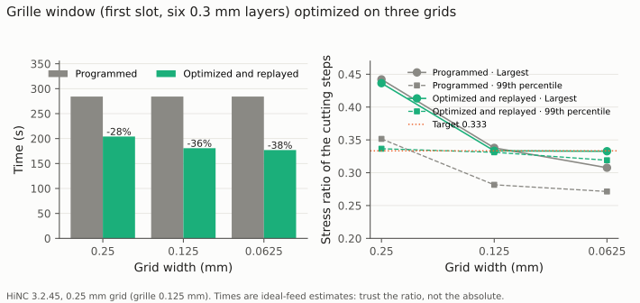
The same slot on three grids. At 0.25 mm the stress tail is the grid's, and it costs a quarter of the gain.
4. A prediction missed on the fast side
- Situation. The plan predicted the cover's OP10 at −15 to −30 % in V1; it came out at −46.0 %.
- Risk. A prediction missed either way says the picture of the program was wrong: taking the result without an explanation, or distrusting a correct one.
- How noticed. O4.
- Resolution. The comparison of the CAM's hand-written rules (O8) explains it. 72 % of the cover's roughing time is the CAM's half-feed laps: 911.4 s on the full-width first laps and 337.2 s on the ramp entries, both at F960, of 1,726.0 s. HiNC reads those laps far under its targets and the optimizer sends them at the 0.12 mm ceiling, F2880, three times their feed. On the shell the same laps are 22.5 % of the roughing. The CAM's “full width at half feed” rule is too cautious for a Ø12 cutter in aluminium on this spindle. O4 for the cover's V1 is reported as not met, as written.
- Evidence. The rule table and chart under Results and benefits.
5. One wall step at 26.7 µm
- Situation. V2's replay of the shell keeps one wall step at 26.7 µm and 12 floor steps over 25.5 µm (at most 26.5 µm).
- Risk. Calling B1 met with steps over it, or calling the approach broken for one step.
- How noticed. O5.
- Resolution. The wall step is at the corner at the X end, (90.5, 55.0, −24.0): the replay reads the whole 19.03 mm flute engaged there and 257 N, where the baseline at the same point read 5 mm, 194 N and 22.0 µm. A re-interpolated feed moves the points at which HiNC samples the cut, and a corner's reading moves with them; NC Optimization says a replay can read slightly above its targets for this reason. The 12 floor steps are held at the target force (210 N against 207.1 N), but their compliance, 0.126 µm/N, lies above the 95th-percentile compliance, 0.1207 µm/N, the target was derived from: by design the target covers 95 % of the steps. O5 for the shell's V2 is reported as not met. One more correction belongs here: the amendment had placed the shell's largest B1 reading on a ramp; the whole-program play put it on the full-feed lap at F1440 right after the ramp, which cuts the wedge the ramp leaves. The results correct it; the amendment's text is kept as written.
- Evidence. The B1 table: the shell's walls 42.6 → 26.7 µm and floors 38.8 → 26.5 µm, both far closer to 25 µm than the source program.
6. The target force's share on the cover
- Situation. O2 asks 99 % of V2's finishing cutting steps at or under the target force × 1.02. On the cover's walls 613 steps are over 263.1 × 1.02 N: 94.9 % within.
- Risk. Reading the miss as the cover bending past B1.
- How noticed. O2.
- Resolution. Those steps lie on the ramp lines, where the target force does not act (dilemma 2), and the line ceilings held their bend instead: on those steps the cutter's compliance, its bend per newton, is 0.068 µm/N against the 0.0950 µm/N the target was derived from, so even over the target force they stay under 24.2 µm. O2 for the cover's V2 is reported as not met; B1 itself is met.
- Evidence. The criteria table.
7. Hundreds of script errors in a clean replay
- Situation. Every replay of a Ø12 program reports
Script-Compile--Error: 488 (shell V1), 197 (cover V1), 613 (shell V2) and 241 (cover V2); the grille's reports none. - Risk. A replay full of errors can hide a real one; or the embedded settings could be lost in the optimized file.
- How noticed. O1's count of messages the optimization play did not have.
- Resolution. The count equals the number of optimized lines that carry an embedded setting
(@@…)and, after it on the same line, the optimizer's source note(src(LineNo: …)): 488 of 488 on the shell's V1, while the 6 lines with a setting and no note compile. HiNC reads a parenthesised comment from the first(to the last)on its line, as Script Commands in NC Code states, so reading the optimized file back compiles the note as part of the embedded script (error CS7017, at the column where the first comment closes). A ten-second program shows it on its own: a script comment followed by another comment on the same line fails, the same script comment last on the line compiles. The settings are optimization settings and do nothing in a replay; the motion is unaffected, and a controller reads both as comments. O1 for the four Ø12 replays is reported as not met, as written. - Evidence. No collision, stroke or rapid-cut alarm in any replay; every line ran (the criteria table).
8. Points a few micrometres off their source line
- Situation. O3 (a) walks every point of the optimized file back to its source line: on the cover, 71 points lie 1 to 5.3 µm off.
- Risk. A path that differs from the programmed one, written into a file a machine would run.
- How noticed. O3 (a).
- Resolution. All 71 are on roughing lines: long straight moves whose Y changes by only about 0.006 mm. Where the optimizer splits such a line, its pieces carry the source line's end value of Y, so each piece steps off the line by up to the line's own small change in Y. O3 for the cover is reported as not met.
- Evidence. The agent's z-maps and HiNC's exported parts read the same after the optimized program as after the source (the shape table).
9. One air-feed move over a sliver
- Situation. O6 walks every optimized program over the agent's own 0.1 mm z-map. On the shell's roughing one move at the 10,000 mm/min air feed, 0.68 mm long at Z −38.24, clips 0.06 mm³ off a stock edge 5.98 mm deep — one column of nodes. V1 and V2 write the same move.
- Risk. A feed move at 10,000 mm/min through stock.
- How noticed. O6.
- Resolution. HiNC's 0.25 mm grid read no contact on that move in either play: the sliver is narrower than one of its cells, so HiNC reads air and the optimizer sends the air feed. O6 for the shell is reported as not met, as written. The cover's and the grille's optimized programs have no such move.
- Evidence. The air-feed table under Results and benefits.
10. Plunges read as the cutter's whole face
- Situation. The grille's plunges, programmed at F150, come out at a median of F104, the cutter's minimum chip of 0.004344 mm per tooth; 65 % of the replay's plunge time runs slower than programmed. In V2 some of the Ø12 finishing plunges go to F104 too.
- Risk. Time lost where nothing heavy happens, or a stress reading taken at face value.
- How noticed. O8, and the per-step log on the plunges.
- Resolution. HiNC reads a plunge's contact as the whole face of the cutter, so the stress criterion slows the grille's plunges to the minimum chip; the Ø12 finishing plunges are slowed by their line ceilings, because their baseline bend read high. The cost is small — the grille's plunges take 68.5 s of its 75.5 min — and the plunges were left to the optimizer rather than exempted.
- Evidence. The rule table under Results and benefits.
11. A tie at the cutter's radius
- Situation. In the cover's trial the agent's z-map comparison first read 448 nodes 13.4 mm apart between the source and the optimized program.
- Risk. A changed shape that is not there — or, the other way round, a habit of dismissing differences.
- How noticed. O3 (b) in the trial.
- Resolution. The nodes lie exactly on the cutter's radius, a floating-point tie whether the cutter touches them. The check now counts a node as cut only when it lies 1 µm inside the radius; recomputed, the two z-maps are 100 % alike.
- Evidence. Every whole-program comparison 100 % within 1 µm, but one such node, 4.47 mm, on a finished wall in V2's shell (99.99995 %).
12. 57 GiB on a shared server
- Situation. An optimization play of a Ø12 program peaked at 54–57 GiB of the instance's memory in its optimization stage, about 175 kB a step, on a server that also runs live services.
- Risk. A play that takes the server's memory from the services beside it.
- How noticed. The memory samples of the first whole-program play.
- Resolution. The play script gained a guard that stops this instance if the server's free memory falls under 6 GB; it never fired. Every heavy play waited for at least 40 GB free, and V3's memory was estimated from the grille trial at about 26 kB a step before it ran.
- Evidence. V3 peaked at 19.3 GiB; no play failed (the run-cost table).
13. The smaller ones
| What happened | Risk | How it showed | Resolution | Evidence it held |
|---|---|---|---|---|
| The study changed hands after the trials | a play run under an uncommitted change of plan | the server's copy of the plan against the committed one, and the play chain's log | the two differed in line endings only; the amendment and the trial results committed before the first whole-program play | the plan's history |
| The analysis took the held lines' own chips for the minimum feed | 842 of the cover's steps counted as “at the minimum” | the log classes against the held lines | the minimum looked for only between 100 mm/min and 1.5 times it; every log classified again | the limits table |
| The canvas shows the tool where the program ends | a picture with the tool at its retract height | the first picture | picture programs that stop at a pose on the same source line before and after; the colour range set to 0.2–0.8 so that the change shows | the four pictures |
| The T-slot cutter cuts an undercut | an air feed on stock the agent's z-map cannot see | the plan | optimization off for T4 | its 70.6 s unchanged |
| The rest cutters cut R3 corners, where HiNC can over-read a small cutter's load | feeds tuned on readings that may be noise | the plan | held at their programmed chip, so they can only slow down | T3's stress ratio 0.386 → 0.332, T11's 0.477 → 0.333 |
| HiNC's default minimum feed (1 mm/min) and acceleration (10 mm/s²) | one phantom reading stalls a stretch; every feed change spread over hundreds of millimetres | the plan | 100 mm/min and 1,000 mm/s² | the slowest feed written, F104, is the cutters' minimum chip |
| The acceptance ran one tool per run; this study plays each program whole | a whole-program run that cuts less than the acceptance did | O10 | every tool's steps in contact counted | shell T1 / T2 / T3 / T4 211,147 / 6,392 / 850 / 5,778, cover T10 / T11 / T8 205,501 / 654 / 410, each the acceptance's to the step |
| The lock shared with other studies | a heavy play started on a busy server | the queue | every play waited its turn, 9–20 min each | the chain ran in order; no play failed |
Results and benefits
Measured on HiNC 3.2.45 at a 0.25 mm grid, the grille at 0.125 mm, each program whole in one run. Times are HiNC's ideal-feed estimates; trust the ratios rather than the absolute minutes.
| Program | Source | V1 | V2 | V3 | Predicted |
|---|---|---|---|---|---|
| Bottom shell OP10 | 2,261.7 s (37.7 min) | 1,753.3 s (29.2 min), −22.5 % | 1,631.1 s (27.2 min), −27.9 % | — | V1 −12 to −25 % |
| Top cover OP10 | 2,378.9 s (39.6 min) | 1,285.7 s (21.4 min), −46.0 % | 1,140.8 s (19.0 min), −52.0 % | — | V1 −15 to −30 % |
| Back panel OP10, grille stage | 7,231.4 s (120.5 min) | — | — | 4,532.1 s (75.5 min), −37.3 % | −30 to −55 % |
| The three programs | 197.9 min | 126.2 min with V1 | 121.7 min with V2 |
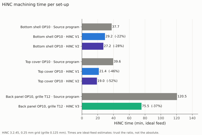
The three programs before and after.
| Class of pass (tool) | Shell: source → V1 → V2 | Cover: source → V1 → V2 |
|---|---|---|
| Roughing (Ø12) | 1,235.7 → 720.4 → 720.4 s | 1,726.0 → 627.2 → 627.2 s |
| Wall finishing (Ø12) | 271.2 → 271.5 → 282.8 s | 155.7 → 156.3 → 115.7 s |
| Floor finishing (Ø12) | 581.4 → 586.6 → 453.0 s | 455.5 → 459.4 → 355.0 s |
| Rest machining | T2 91.6 → 91.9 → 91.9 s; T3 6.2 → 7.3 → 7.3 s | T11 17.1 → 18.2 → 18.2 s |
| Not optimized | T4 T-slot 70.6 s; tool changes and rapids 5.1 s | T8 drilling 22.0 s; tool changes and rapids 2.6 s |
The back panel's grille stage in V3: the grille cutter 7,230.2 → 4,530.9 s, the tool change and rapids 1.2 s.
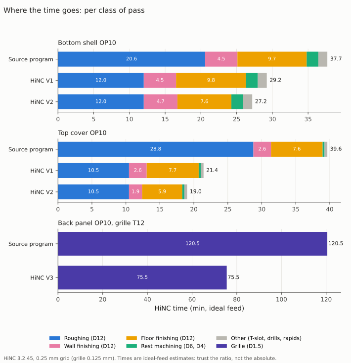
Most of the gain is the roughing; V2 adds what the finishing gives back.
Where the time comes from, by the agent's walk of each program on its own stock model (the drilling cycles left out), every move counted as cutting feed, feed through air or rapid:
| Program | Cutting feed | Feed through air | Rapids |
|---|---|---|---|
| Shell: source → V1 → V2 | 1,542.3 → 1,154.8 → 1,046.1 s | 588.6 → 467.7 → 454.1 s | 124.0 s |
| Cover: source → V1 → V2 | 1,571.8 → 817.2 → 665.2 s | 740.0 → 401.2 → 408.2 s | 41.8 s |
| Grille: source → V3 | 5,339.9 → 3,111.3 s | 1,886.4 → 1,415.7 s | 2.4 s |
Of the 76.1 minutes the three programs save with V2 and V3, 60.5 are cutting and 15.6 feed through air; the walk's totals lie within about 1 % of HiNC's times.
The Ø12 roughing: the chip is the limit, not the spindle
| Roughing | Shell, T1 (54 mm out) | Cover, T10 (32 mm out) |
|---|---|---|
| Time | 1,235.7 → 720.4 s (−41.7 %) | 1,726.0 → 627.2 s (−63.7 %) |
| What set the feed (cutting steps) | ceiling 98.4 %, spindle power 1.6 %, stress 0.1 % | ceiling 99.6 %, spindle power 0.3 %, stress 0.1 % |
| Spindle power ratio, short-term, largest (target 0.667) | 0.788 → 0.664 | 0.463 → 0.665 |
| Cutting steps over 0.667 × 1.02 | 2,076 → 0 | 0 → 0 |
| Continuous power ratio, largest (reported only) | 1.010 → 0.850 | 0.593 → 0.853 |
| Spindle input power, median / largest | 1.68 / 9.33 → 2.96 / 7.85 kW | 0.77 / 5.48 → 1.26 / 7.87 kW |
| Stress ratio, largest | 0.198 → 0.216 | 0.213 → 0.288 |
| XY tip deflection, p99 / largest (B2: 95th percentile ≤ 100 µm) | 71.5 / 72.6 → 75.5 / 79.7 µm | 24.2 / 39.7 → 46.4 / 58.7 µm |
| Feed per tooth, median | 0.08 → 0.12 mm | 0.04 → 0.12 mm |
At 8,000 min⁻¹ the αT12 gives 11.8 kW on its short-term curve; the target, 67 % of it, is 7.9 kW. The steady roughing at 0.12 mm reads a power ratio of only 0.33 — half the target — and only the full-width cut that opens each level reaches it. The spindle at this speed would take a larger chip than the ceiling allows; the 0.12 mm ceiling, 1.5 times the programmed chip and under the catalogue's roughing value, sets the speed. Where the source program was heaviest it is now slower, and faster everywhere else.
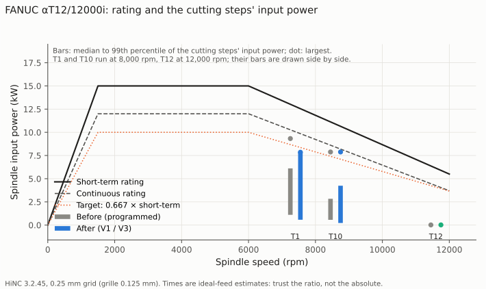
The spindle's ratings and the cutting steps' input power: the shell's full-width cuts above the target before, on it after.
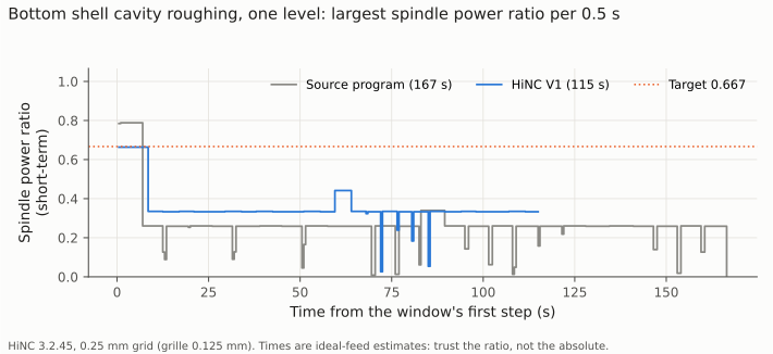
One level of the shell's cavity: the full-width opening cut brought from 0.79 to the target, the rest of the level raised from 0.26 to 0.33.
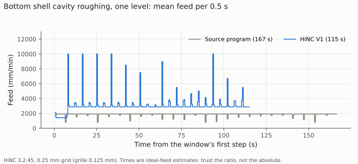
The same level's feed: the full-width opening cut slowed from 1,920 to about 1,430 mm/min, the rest raised to 2,880, the air feed between passes.
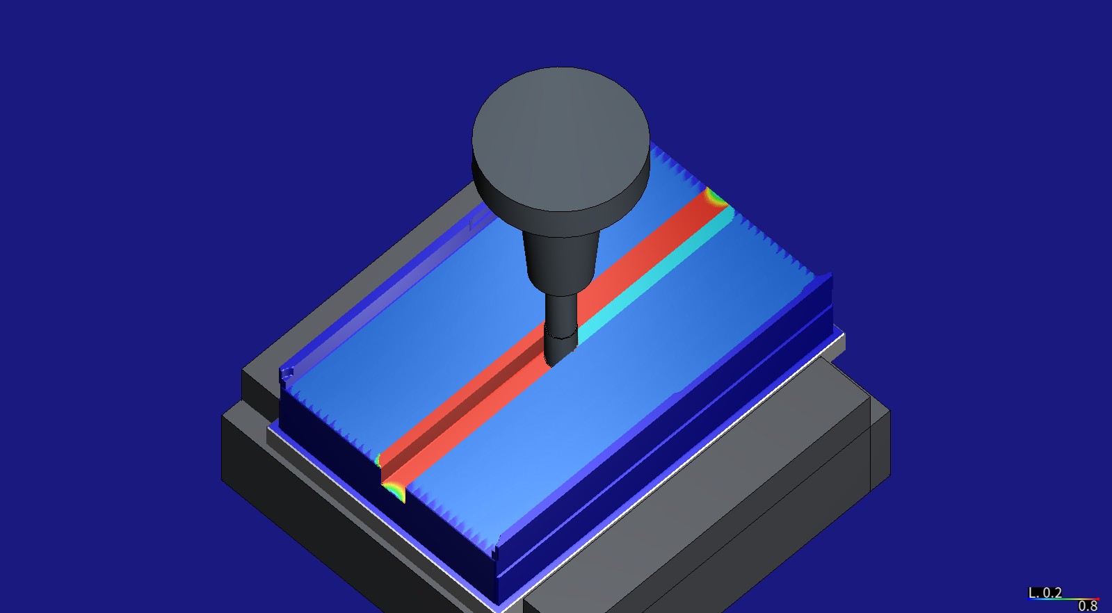
Before: the source program, the same pose and colouring as the picture at the top (spindle power ratio, 0.2 to 0.8). The full-width opening cut reads about 0.8 (red), the rest of the floor about a quarter (blue).
The CAM's hand-written feed rules against the optimizer (O8), the Ø12 roughing in V1:
| Rule | Programmed | Shell: time, source → V1 | Shell: optimized median feed (10th–90th percentile) | Cover: time, source → V1 | Cover: optimized median feed |
|---|---|---|---|---|---|
| Full-feed passes | F1920 | 878.7 → 567.0 s | 2,880 (2,880–2,880) | 441.2 → 215.4 s | 2,880 (2,880–10,000) |
| Rest of the first lap, half feed | F960 | 184.9 → 54.2 s | 2,880 (2,880–10,000) | 911.4 → 263.9 s | 2,880 (2,861–2,880) |
| Ramp entries, half feed | F960 | 93.1 → 29.8 s | 2,880 (1,994–2,880) | 337.2 → 115.4 s | 2,869 (2,857–2,880) |
| Links across a full slot, 40 % | F768 | — | — | 0.3 → 0.1 s | 2,880 |
| Plunges | F800 | 11.3 → 1.7 s | 2,880 (104–10,000); a third of the plunge time slower | 5.7 → 2.4 s | 1,492 (1,492–2,186) |
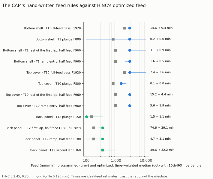
Each rule's programmed feed (grey) and the optimized time-weighted median (dot) with its 10th–90th percentile; on the right, the time before and after.
The Ø12 finishing and the rest cutters by rule, V1 (held) and V2 (line ceilings and target force)
| Lines | Programmed | V1: time, source → replay; median feed | V2: time; median feed (10th–90th percentile) |
|---|---|---|---|
| Shell walls, full-feed lap | F1440 | 243.7 → 243.8 s; 1,440 | 260.9 s; 1,824 (180–1,824) |
| Shell walls, half-feed first lap | F720 | 1.7 → 1.7 s; 720 | 0.7 s; 1,824 |
| Shell walls, ramps | F720 | 9.5 → 9.7 s; 720 | 4.9 s; 1,824 (104–1,824) |
| Shell walls, plunges | F800 | 2.2 → 2.3 s; 800 | 2.3 s; 800 (104–1,603) |
| Shell floors, full-feed lap | F1440 | 158.6 → 159.3 s; 1,440 | 151.2 s; 1,814 (840–1,824) |
| Shell floors, half-feed first lap | F720 | 311.6 → 311.6 s; 720 | 216.3 s; 720 (720–1,824) |
| Shell floors, ramps | F720 | 87.0 → 90.1 s; 720 | 55.7 s; 1,394 (104–1,824) |
| Shell floors, plunges | F800 | 6.5 → 7.9 s; 800 | 12.8 s; 104 (104–964) |
| Cover walls, full-feed lap | F1440 | 77.8 → 77.9 s; 1,440 | 64.0 s; 1,824 |
| Cover walls, half-feed first lap | F720 | 31.8 → 31.8 s; 720 | 22.8 s; 1,824 (104–1,824) |
| Cover walls, ramps | F720 | 42.7 → 42.9 s; 720 | 24.7 s; 1,824 (144–1,824) |
| Cover walls, plunges | F800 | 0.8 → 0.9 s; 800 | 1.5 s; 104 (104–1,824) |
| Cover floors, full-feed lap | F1440 | 146.5 → 146.9 s; 1,440 | 126.1 s; 1,824 (1,440–1,824) |
| Cover floors, half-feed first lap | F720 | 258.6 → 258.6 s; 720 | 178.6 s; 720 (720–1,824) |
| Cover floors, ramps | F720 | 38.0 → 40.3 s; 720 | 32.0 s; 104 (104–1,824) |
| Cover floors, plunges | F800 | 4.2 → 5.3 s; 800 | 11.0 s; 104 (104–800) |
| Shell rest T2, full-feed lap | F1080 | 51.5 → 51.6 s; 1,080 | as V1 |
| Shell rest T3 | F900 | 4.6 → 5.7 s; 598 (598–900) | as V1 |
| Cover rest T11, full-feed lap | F1440 | 6.9 → 7.6 s; 1,440 (638–1,440) | as V1 |
| Shell T-slot cutter T4 (not optimized) | F1080 | 65.7 → 65.7 s; 1,080 | as V1 |
The finishing and B1
| XY tip deflection, p99 / largest | Shell walls | Shell floors | Cover walls | Cover floors |
|---|---|---|---|---|
| Source program | 19.9 / 42.6 µm | 25.1 / 38.8 µm | 30.6 / 36.5 µm | 17.4 / 17.5 µm |
| V1: held at the programmed chip | 19.9 / 42.6 µm | 25.1 / 38.8 µm | 30.5 / 36.5 µm | 17.4 / 17.5 µm |
| V2: target force and line ceilings | 20.5 / 26.7 µm | 24.3 / 26.5 µm | 22.5 / 24.2 µm | 20.4 / 20.5 µm |
| V2: steps over 25.5 µm, not at the minimum | 1 | 12 | 0 | 0 |
| Time: source → V1 → V2 | 271.2 → 271.5 → 282.8 s | 581.4 → 586.6 → 453.0 s | 155.7 → 156.3 → 115.7 s | 455.5 → 459.4 → 355.0 s |
| V2: target force | 207.1 N | 207.1 N | 263.1 N | 263.1 N |
| V2: what set the feed (cutting steps) | ceiling 97.0 %, a lowered line ceiling 2.8 %, target force 0.2 % | ceiling 95.0 %, a lowered line ceiling 2.9 %, target force 1.8 %, stress 0.2 % | ceiling 97.6 %, a lowered line ceiling 1.3 %, the minimum by the target force 0.7 %, target force 0.3 % | ceiling 99.2 %, target force 0.6 %, stress 0.1 % |
| V2: replay steps at the minimum feed, listed apart | 488 | 2,218 | 1,731 | 2,202 |
The finishing in V2 runs faster than in V1 on three of the four classes: most finishing lines bent far under 25 µm in V1, so their ceilings rose to 0.076 mm, and only the lines at the open ends and the corners, where a pass meets more than its allowance, were slowed. The shell's walls take 11.6 s longer than in the source program for a largest step 15.9 µm lower.
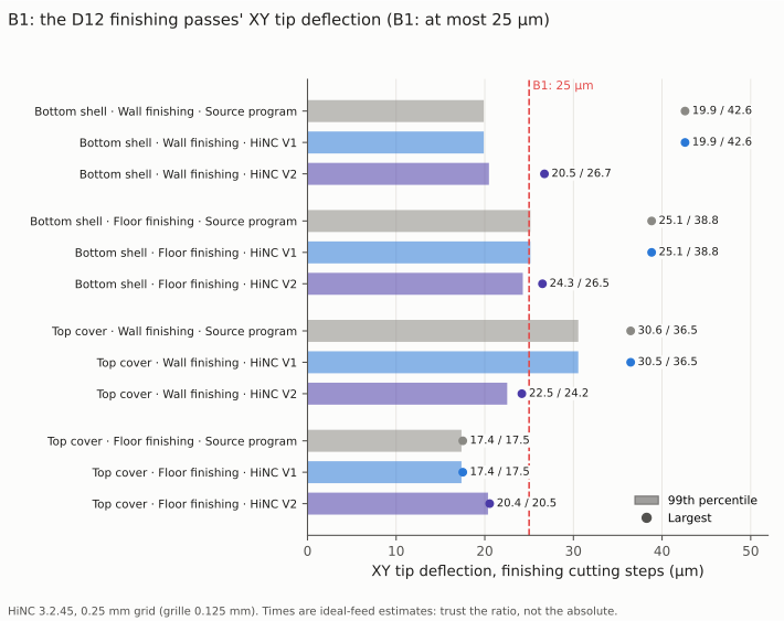
B1 per class: V1 leaves the finishing as programmed, V2 brings every largest step to 25 µm or within 2 µm of it.
The grille: the half-feed lap was the time
| Back panel grille, T12 | Source program | V3, replayed |
|---|---|---|
| Time | 7,231.4 s (120.5 min) | 4,532.1 s (75.5 min), −37.3 % |
| What set the feed (cutting steps) | — | ceiling 99.2 %, stress 0.8 %, the minimum by the stress 209 steps |
| Stress ratio, p99 / largest (target 0.333) | 0.282 / 0.338 | 0.331 / 0.333 |
| Cutting steps over 0.333 | 126 | 0 |
| XY tip deflection, p95 / p99 / largest (B2: p95 ≤ 100 µm) | 49.0 / 49.0 / 59.4 µm | 57.4 / 57.6 / 58.8 µm |
| Largest force | 12 N | 12 N |
| Feed per tooth, median | 0.0075 mm | 0.015 mm |
| Spindle power ratio, largest | 0.003 | 0.004 |
| Grille, by the CAM's rule | Programmed | Time, source → V3 | Optimized median feed (10th–90th percentile) | Share of V3's time faster / slower than programmed |
|---|---|---|---|---|
| First lap of each layer, a full slot | F180 | 4,475.8 → 2,343.5 s | 360 (264–360) | 96 % / 4 % |
| Ramps | F180 | 281.5 → 185.0 s | 360 (104–360) | 66 % / 34 % |
| Second lap | F360 | 2,378.5 → 1,929.9 s | 360 (360–1,010) | 13 % / 0 |
| Plunges | F150 | 90.5 → 68.5 s | 104 (104–360) | 35 % / 65 % |
The time comes from the half-feed first lap, raised to the programmed chip, and from the stretches of the second lap that touch nothing, sent at the 1,010 mm/min air feed.
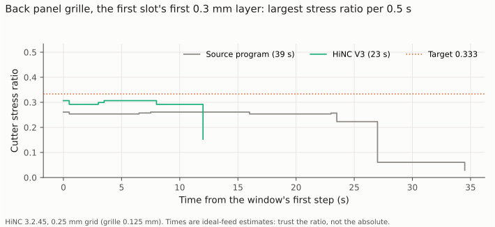
One layer of the first slot: the stress rises from about 0.25 to about 0.30, under the target, for 23 s instead of 39.
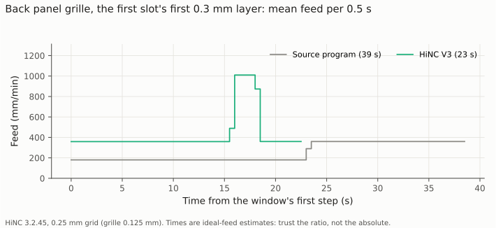
The same layer's feed: the first lap 180 → 359 mm/min; the second lap stays at 360, its stretch through air at the 1,010 mm/min air feed.
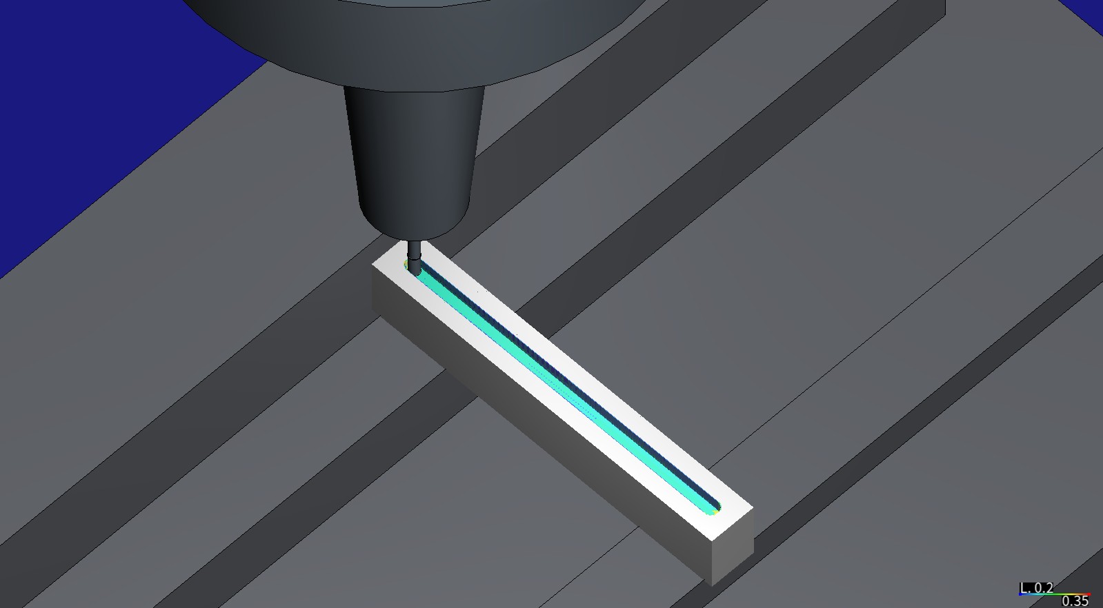
Before: the Ø1.5 mm long-neck cutter, 14 mm out of its shrink-fit chuck, partway through the first slot's six layers, played on a block of stock around the slot. The faces it cut are coloured by stress ratio, 0.2 (blue) to 0.35 (red): blue-green, about 0.25.
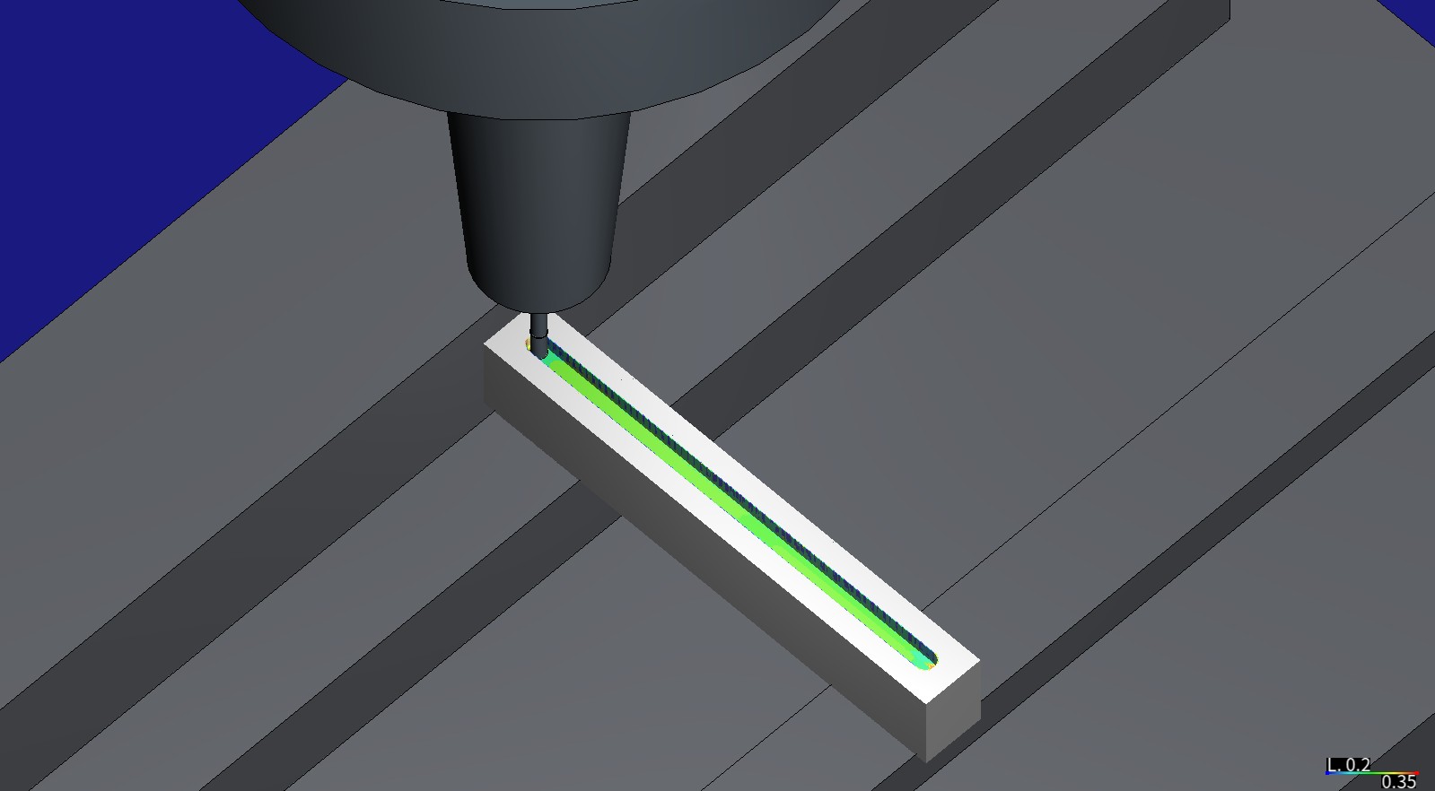
After V3, the same pose and colouring: green, about 0.3, at twice the feed of the first lap.
Loads and what set the feed
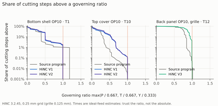
The share of cutting steps above each governing ratio. After the optimization every tool ends at its target; the light steps rise toward it.
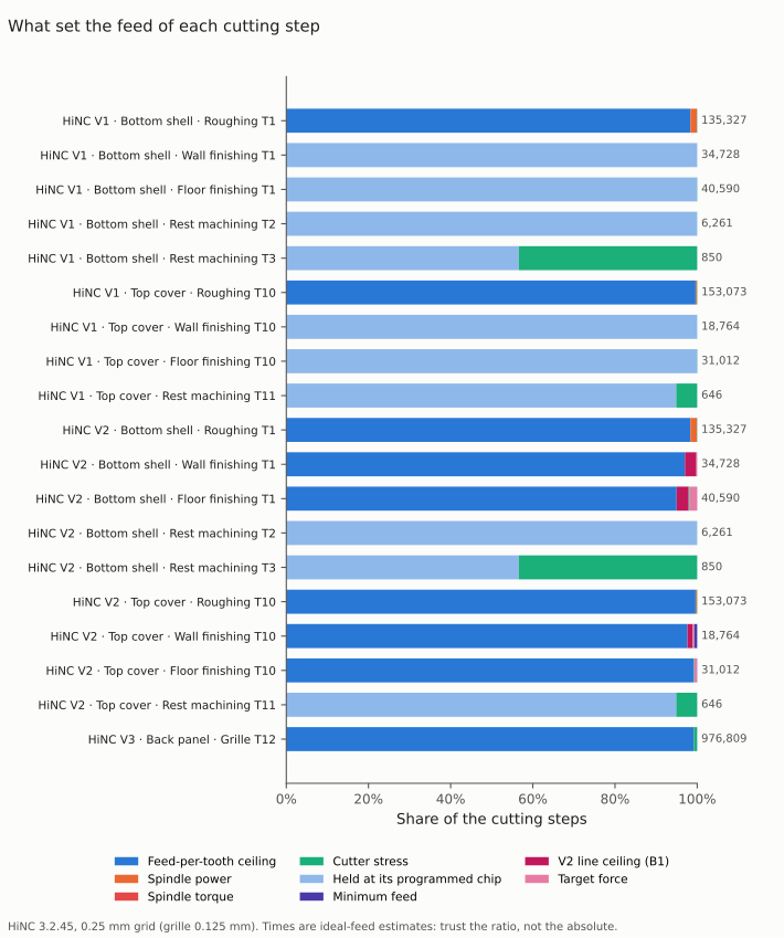
The criterion that set each cutting step's feed, from the optimizer's per-step log; the number on the right counts the cutting steps.
| Play · class | Cutting steps | Ceiling | Held at its own chip | Lowered line ceiling | Spindle power | Stress | Target force | The minimum |
|---|---|---|---|---|---|---|---|---|
| V1 / V2 shell roughing T1 | 135,327 | 98.4 % | 1.6 % | 0.1 % | 1 step (V2) | |||
| V1 shell walls T1 | 34,728 | 100.0 % | 2 steps | |||||
| V1 shell floors T1 | 40,590 | 99.9 % | 0.1 % | |||||
| V1 / V2 shell rest T2 | 6,261 | 100.0 % | 1 step | |||||
| V1 / V2 shell rest T3 | 850 | 56.6 % | 43.4 % | |||||
| V1 / V2 cover roughing T10 | 153,073 | 99.6 % | 0.3 % | 0.1 % | ||||
| V1 cover walls T10 | 18,764 | 100.0 % | 2 steps | |||||
| V1 cover floors T10 | 31,012 | 99.9 % | 0.1 % | |||||
| V1 / V2 cover rest T11 | 646 | 94.9 % | 5.1 % | |||||
| V2 shell walls T1 | 34,728 | 97.0 % | 2.8 % | 1 step | 2 steps | 0.2 % | 3 steps | |
| V2 shell floors T1 | 40,590 | 95.0 % | 2.9 % | 2 steps | 0.2 % | 1.8 % | 14 steps | |
| V2 cover walls T10 | 18,764 | 97.6 % | 1.3 % | 6 steps | 0.3 % | 0.7 % | ||
| V2 cover floors T10 | 31,012 | 99.2 % | 0.1 % | 0.6 % | 14 steps | |||
| V3 grille T12 | 976,809 | 99.2 % | 0.8 % | 209 steps |
Spindle torque set 7 steps of the shell's roughing, 3 of the cover's and 6 of V2's shell floors.
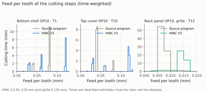
At which feed per tooth the cutting time runs: the Ø12 roughing moves to the 0.12 mm ceiling, the grille cutter from its half-feed lap to its programmed chip.
The criteria
| # | V1 shell | V1 cover | V2 shell | V2 cover | V3 grille |
|---|---|---|---|---|---|
| O1 | not met as written: 488 Script-Compile--Error (dilemma 7); 0 collisions, 0 stroke alarms, 0 rapid cuts, every line run |
not met: the same, 197 | not met: the same, 613 | not met: the same, 241 | met |
| O2 | met: power, torque and stress 100 % | met | met | not met: target force 94.9 % (dilemma 6); power, torque and stress 100 % | met: stress 100 % |
| O3 | met: (a) 0 points off; (b) 2,050,421 nodes 100 % within 1 µm; (c) volume −0.000 % | not met: (a) 71 points 1–5.3 µm off (dilemma 8); (b), (c) met | met: (b) 1 node 4.47 mm, a tie on a finished wall (99.99995 %) | not met: (a) as V1 | met: (b) 1,958,121 nodes (0.05 mm) 100 % |
| O4 | met: −22.5 % | not met: −46.0 %, faster than predicted (dilemma 4) | met: not slower than V1 | met | met: −37.3 % |
| O5 | met: not above the baseline | met | not met: 1 wall step 26.7 µm, 12 floor steps (dilemma 5) | met: walls 24.2 µm | met: p95 57.4 µm |
| O6 | not met: 1 move at F10000 over 0.06 mm³ (dilemma 9) | met | not met: the same move | met | met |
| O7 | met: 28,203 → 29,113 lines, 813 → 1,882 F words, 494 settings carried | met | met | met | met |
| O8 | reported | reported | reported | reported | reported |
| O9 | roughing 98.4 % at the ceiling | roughing 99.6 % | finishing: the B1 table | the same | 99.2 % at the ceiling |
| O10 | met: every tool 1.000 | met | met | met | met: one tool; 0.125 against 0.25 mm contact 1.152, the window trial's 1.153 |
O9's predictions: V1's roughing at least 80 % at the ceiling, as predicted; the full-width cuts set by the spindle power, as predicted (1.6 % and 0.3 % of the steps); V2's finishing mostly at 0.076, as predicted, but the cover's X end set by the line ceilings rather than the target force, which does not reach the ramps; V3 mostly at the ceiling, as predicted.
The optimized files (O7). The optimizer gives a line a new feed or splits it where the feed changes along it; every embedded setting is carried into the output:
| Program | Lines, source → optimized | F words | Feeds written | Lines at the air feed | Embedded settings carried | Lines with a source note |
|---|---|---|---|---|---|---|
| V1 shell | 28,203 → 29,113 | 813 → 1,882 | 104–10,000 mm/min | 617 at 10,000 | 494 of 494 | 27,096 |
| V1 cover | 10,510 → 12,623 | 410 → 2,447 | 406–10,000 mm/min | 998 at 10,000 | 201 of 201 | 10,059 |
| V2 shell | 28,203 → 29,728 | 813 → 2,684 | 104–10,000 mm/min | 617 at 10,000 | 619 of 619 | 27,096 |
| V2 cover | 10,510 → 12,973 | 410 → 2,845 | 104–10,000 mm/min | 998 at 10,000 | 245 of 245 | 10,059 |
| V3 grille | 12,409 → 14,005 | 468 → 1,752 | 104–1,010 mm/min | 183 at 1,010 | 1 of 1 | 12,000 |
The shape (O3), each optimized program against its source:
| Program | (a) points more than 1 µm off their source line | (b) the agent's z-map, nodes alike within 1 µm | (c) HiNC's exported part: volume, source → replay |
|---|---|---|---|
| V1 shell | 0 of 29,038 | 2,050,421 nodes (0.1 mm), 100 % | 223,139.05 → 223,139.04 mm³ |
| V1 cover | 71 of 12,566, at most 5.3 µm, all on roughing lines | 2,050,421 nodes, 100 % | 194,956.01 → 194,955.99 mm³ |
| V2 shell | 0 of 29,653 | 2,050,421 nodes, 100 % but one tie at 4.47 mm | 223,139.05 → 223,140.57 mm³ (+0.0007 %) |
| V2 cover | 71 of 12,916, as V1 | 2,050,421 nodes, 100 % | 194,956.01 → 194,956.87 mm³ (+0.0004 %) |
| V3 grille | 0 of 13,985 | 1,958,121 nodes (0.05 mm), 100 % | 37,438.40 → 37,438.44 mm³ (+0.0001 %) |
The air-feed guard (O6), every optimized program walked over the agent's z-map in play order:
| Program | Moves walked | Moves cutting above their line's ceiling × 1.02 | Rapid moves into stock |
|---|---|---|---|
| V1 shell | 29,033 | 1: optimized line 9,378, F10000 against a ceiling of 2,880, 0.06 mm³, 5.98 mm deep, 0.68 mm long at Z −38.24 | 0 |
| V1 cover | 12,563 | 0 | 0 |
| V2 shell | 29,648 | 1: the same move (optimized line 9,448) | 0 |
| V2 cover | 12,913 | 0 | 0 |
| V3 grille | 13,984 | 0 | 0 |
Every tool cuts (O10): in the whole-program runs the shell's T1, T2, T3 and T4 touch 211,147, 6,392, 850 and 5,778 steps and the cover's T10, T11 and T8 205,501, 654 and 410 — each the same count, to the step, as the case's acceptance, which ran one tool per run.
The trials on the X-end windows (stock only in the 25.5 mm at the +X end, so most of the roughing there runs in the air and the time ratios are not whole-program predictions) and on the grille slot, with the plan's first settings — the ones dilemmas 1 and 2 then changed:
| Trial (source → optimized, replayed) | HiNC time | Finishing XY tip deflection, p99 / largest | What set the feed (cutting steps) |
|---|---|---|---|
| Shell X end, V1 settings | 437.0 → 188.1 s | 9.5 / 21.9 → 9.5 / 21.9 µm | roughing and finishing 100 % at the ceiling |
| Shell X end, V2 settings | 437.0 → 184.3 s | 9.5 / 21.9 → 10.4 / 25.6 µm | the same |
| Cover X end, V1 settings | 314.7 → 118.6 s | 33.3 / 36.5 → 41.7 / 43.6 µm | finishing 97.3 % ceiling, 2.6 % power |
| Cover X end, V2 settings | 314.7 → 123.4 s | 33.3 / 36.5 → 41.9 / 44.4 µm | finishing 94.3 % ceiling, 3.5 % target force, 2.1 % power |
| Grille slot at 0.25 / 0.125 / 0.0625 mm | 284.2 → 204.1 / 180.7 / 176.9 s | — | the grid table under dilemma 3 |
Every trial ran without a warning or an error; every optimized file differed from its source, every optimized point lay on its source line, the agent's z-maps read alike and no air feed touched stock.
The X-end windows' baselines, played on their own:
| Window baseline | Finishing XY tip deflection, p99 / largest | Finishing force, p99 / largest | Finishing power ratio, largest | Compliance, p50 / p95 | XY tip deflection, p99, every cutting step |
|---|---|---|---|---|---|
| Shell, T1 (54 mm out) | 9.5 / 21.9 µm | 94 / 199 N | 0.063 | 0.1008 / 0.1010 µm/N | 32.7 µm |
| Cover, T10 (32 mm out) | 33.3 / 36.5 µm | 593 / 654 N | 0.666 | 0.0644 / 0.0851 µm/N | 31.4 µm |
The windows' readings at 0.125 mm differ from these by at most 8 %. The cover's finishing step that meets the stock at its X end, 654 N, already reads a power ratio of 0.666, at the default target.
What the runs cost, on the shared 32-thread server:
| Play | Grid | Steps | Server time | Peak memory of the instance |
|---|---|---|---|---|
| V1 shell: optimization / replay | 0.25 mm | 319,907 / 252,869 | 750.7 / 460.4 s | 54.3 / 3.8 GiB |
| V1 cover: optimization / replay | 0.25 mm | 323,089 / 177,599 | 520.6 / 220.2 s | 32.5 / 2.5 GiB |
| V2 shell: optimization / replay | 0.25 mm | 319,907 / 236,561 | 751.1 / 450.5 s | 56.8 / 3.7 GiB |
| V2 cover: optimization / replay | 0.25 mm | 323,089 / 158,434 | 510.5 / 210.2 s | 31.4 / 2.2 GiB |
| V3 grille: optimization / replay | 0.125 mm | 1,451,705 / 913,985 | 690.7 / 360.4 s | 19.3 / 4.1 GiB |
| X-end windows: baselines at 0.25 and 0.125 mm | 58,993 (shell), 42,400 (cover) | 30–220 s | 1.0–2.1 GiB | |
| X-end trials: optimization / replay | 0.25 mm | 58,993 / 25,224–25,788; 42,400 / 16,328–16,926 | 30–50 / 20 s | 2.7–3.9 / 0.9–1.0 GiB |
| Grille slot: baselines at three grids | 57,057 | 30–40 s | 0.8–1.0 GiB | |
| Grille slot trials: optimization / replay, and the cross-grid replay | 57,057 / 35,644–41,109 | 30–60 / 20–30 s | 1.9–3.6 / 0.8–0.9 GiB | |
| Four picture plays | 0.25, 0.125 mm | 26,567–93,909 | 20–230 s | 0.8–2.4 GiB |
| The script-comment reproduction | 1 mm | 453 | 10 s | 0.6 GiB |
The ten whole-program plays took 82 minutes of server time and the trials, pictures and reproduction 23 more, each heavy play after a wait of 9 to 20 minutes on the shared lock. An optimization play of a Ø12 program needed 13 to 15 times the memory of its replay, the grille's about 5 times.
For a machining engineer. On two thin-walled aluminium parts and a grille, HiNC's feed optimization took 76 minutes off three programs without moving a toolpath. It showed that the Ø12 roughing is limited by the chip the agent allowed, not by the spindle: at 8,000 min⁻¹ steady roughing at that chip drew only half of the αT12's power target, and only the full-width cut that opens each level — where the program had asked more than the continuous rating — needed slowing. The CAM's habit of halving the feed on every ramp and first lap was the largest single waste, 72 % of the cover's roughing. The finishing was protected two ways: held line by line at its programmed chip, it cuts exactly as programmed; steered by a target force and a ceiling per line from its own measured bend, it got faster and brought the cover within the 25 µm the case asked, the shell to within 2 µm of it. And the grille that the case's grid made look finished had 37 % left in it.
For a teacher or a student. The case shows what to read before trusting an optimizer's limit: which criterion set each step (the per-step log), whether the grid reads a thin layer truly (one slot at three grids), and whether a target acts where it matters (a ramp is not a level step). It shows why a deflection limit is carried by force and why that is weak when the force barely follows the feed, and why a replay can read a corner differently from the play it came from.
For someone weighing the approach. From three accepted programs to optimized ones for both Ø12 set-ups and the grille took ten whole-program plays and 27 small ones, some 105 minutes of server time, with optimization plays of up to 57 GiB. The agent wrote its criteria, settings and decision rules first, changed the plan only by written amendments before the plays they governed, and reported every criterion that failed as written — six of the ten failed somewhere, each with its reason.
Honest limits
- The times are ideal-feed estimates, without the controller's acceleration and look-ahead: the ratios between the source and the optimized programs are sound, the absolute times are not shop-floor times — see Machining Time Estimation.
- Deflection is HiNC's tool-beam reading, not a measurement. B1, the target forces and the line ceilings hold the model's deflection. The case's projects play with HiNC's deflection transformation off, so the shape comparisons read the programmed path, and a larger bend does not show in them.
- The optimizer has no built-in deflection criterion, and the target force that carries one acted here only on steps at a constant height: on the ramp entries it did not hold, and it missed some level steps right after a ramp. The line ceilings stand in for it there; they are drawn from the baseline's bend, so a reading that moves with the re-interpolated feed can still land over 25 µm (one wall step, 26.7 µm).
- HiNC's force follows the chip weakly (n of 0.27 to 0.50): lowering the feed lowers a finishing cutter's bend much less than in proportion, so a tight bend limit costs a lot of feed.
- A replay reads a few steps differently: a re-interpolated feed moves the points where HiNC samples the cut, so a corner can read higher in the replay than in the play it was optimized from.
- Plunges read as the cutter's whole face, and the stress criterion slows them to the minimum chip.
- Reading an optimized file back reports a script error on every line where the optimizer writes its
source note after an embedded setting: HiNC reads a parenthesised comment up to the last
)on the line, so the note is compiled as part of the setting. The motion is unaffected. - A split line can step off its source line by a few micrometres: where a line moves very little along one axis, its pieces keep the line's end value of that axis — up to 5.3 µm here, on roughing lines.
- A sliver narrower than HiNC's cell reads as air and gets the air feed; the agent's own z-map found one such move, over 0.06 mm³.
- The rest cutters, the T-slot cutter, the four OP20 set-ups and the front panel were not optimized; the rest cutters were held because HiNC can over-read a small cutter's load in a corner.
- The walls are rigid in the simulation, the machine, the holders and Al 6061-T6 are generic, and the loads are HiNC's model; chatter, chip evacuation, tool wear and surface finish are not modelled, and nothing was measured on a machine.
What a reader can take to their own case
- Look for the CAM's own caution first. Half feed on ramps and first laps, written as a general rule, was this case's largest single gain; the optimizer's per-rule comparison finds it.
- Hold a finishing pass line by line, not segment by segment, when the CAM writes two chips into one pass; a segment ceiling speeds up the slow lap.
- Check that a target acts where it matters. Compare the per-step log with the steps over the target, separately for steps that change height; a target force that does not act on ramps protects nothing there.
- Draw finishing ceilings from the part's own baseline bend when a target alone does not hold, and raise the lines far under the limit while slowing those over it.
- Play a thin-layer cut at two grids before trusting its tail. A coarse grid can manufacture the limit it then enforces.
- Give the optimizer a minimum feed and an acceleration that make sense; the defaults (1 mm/min, 10 mm/s²) do not.
- Count a replay's messages by line before calling it clean or broken; here hundreds of errors were one cosmetic pattern.
- Budget the memory: an optimization play of a 320,000-step program needed up to 57 GiB, 13 to 15 times its replay.
- Write the decision rules before the plays that decide them, and report the criteria that fail.
Source and licence
- Source: Antmicro, Enclosure for Antmicro baseboard with NVIDIA Jetson AGX Thor,
https://github.com/antmicro/jetson-agx-thor-baseboard-enclosure (branch
main, read 2026-09-30). Search terms if the link moves:antmicro jetson-agx-thor-baseboard-enclosure,cnc-milled-bottom-shell-al. - Licence: Apache License 2.0. The README states “Copyright (c) 2026 Antmicro” and “This project is published under the Apache-2.0 license.” The licence gives the material as is, without warranty.
- Attribution: “Enclosure design (c) 2026 Antmicro, Apache-2.0, https://github.com/antmicro/jetson-agx-thor-baseboard-enclosure. Machining set-up by Tech Coordinate's agent (changes: stock, fixtures, toolpaths).”
- Changed from the original: the part models are used unchanged; the stock, the fixtures, the tools and holders, the set-ups, every program and their optimization here are the agent's; the enclosure's case page tells what the agent made of the parts. The pictures are HiNC simulations of the agent's set-up on Antmicro's models, and the charts are drawn from HiNC's per-step results, the optimizer's per-step log and the agent's own model of the stock. The NVIDIA product name is used only to say what the enclosure fits.
- Backup: the company site keeps a copy of the original files.
See Also
- Jetson AGX Thor Enclosure: A Thin-Walled Aluminium Housing in Eight Set-ups — how the parts, the set-ups, the tools and the programs optimized here were made and accepted
- NC Optimization — what the optimizer holds, the extended distances and why a replay can read above a target
- Workflow: NC Optimization — the settings, the tool limits, settings embedded in NC code and the per-step log
- Optimization Results — measured before-and-after comparisons on other parts
- Machining Time Estimation — why the ratio of two simulated times is the part to trust
- Showcase — the other cases and how a case page reads