Jetson AGX Thor Enclosure: A Thin-Walled Aluminium Housing in Eight Set-ups, with the Agent's Own CAM
Antmicro publishes the enclosure of its NVIDIA Jetson AGX Thor baseboard as open hardware: a U-shaped bottom shell with 38.5 mm walls 3.5 mm thick, a top cover, and front and back panels with vent grilles of 2.0 mm slots, all aluminium, “optimized for compatibility with the popular 3-axis CNC machining process”. The repository gives the parts as STEP files and drawings; it gives no stock, fixture, tool or program. An AI agent wrote its own 2.5-axis CAM for the four parts, planned two set-ups for each (the inside from a thick blank held by a tab, then the part turned over onto a plug), chose the tools and holders from catalogues, wrote eight Fanuc programs and played them in HiNC through the web API.
At a 0.25 mm cell on HiNC 3.2.43 all eight set-ups ran to the end, every one of their 103 operations touched the stock, and no play reported a rapid cut, a collision or a stroke overrun. HiNC's time came within 1 % of the agent's estimate: 382.9 minutes for the four parts, 6.4 hours. The finished parts, exported from HiNC, lie 99.3 to 99.6 % within 0.1 mm plus half a cell of the models; the rest is stock the plan leaves on purpose and the cone of a drill point in flat-bottomed blind holes. Six of the seven criteria written before the first play passed. The one that failed asked the long cutters to bend no more than 25 µm anywhere on a finishing pass: at the 95th percentile they stay within 22 µm, the shell's chamfers aside (35 µm), but single steps reach 28 to 56 µm where a pass meets more stock than its allowance.
Before that, HiNC showed the agent a drill that would have crashed into the vice, a spindle asked for 3.3 times its rating, a Ø1.5 grille cutter bending 0.14 mm, and rapid moves grazing finished walls.
Everything here is simulated: no part was cut on a real machine. The parts are Antmicro's models, unchanged; the stock, fixtures, tools and programs are the agent's. Each dilemma below gives the risk, how it came to light, the resolution and the evidence that it held. The built projects were the agent's working material and are not distributed.
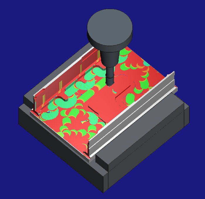
HiNC 3.2.43 during the acceptance. The Ø12 long-reach cutter finishes the shell's cavity floor; its shrink-fit chuck stays above the 38.5 mm wall. A vice holds the blank by the 8.5 mm tab under the part.
The case
The repository (Apache-2.0) holds five machined parts, each as STEP and as a PDF drawing:
| Part | Size (mm) | What makes it work |
|---|---|---|
| Bottom shell | 169 × 111 × 40.5, open at both ends | walls 3.5 mm, 2.5 mm where a 1.0 × 10.5 mm groove runs along the outside; the walls stand 38.5 mm above a 2.0 mm floor; rails, tongues and two pads on the floor; seven countersunk Ø2.7 holes, four Ø3.3 blind holes and a 1/4-20 UNC hole in the floor; a 49° chamfer along both long outer edges |
| Top cover | 169 × 111 × 15.8 | a 2 mm top plate (4.7 mm over the heat-sink area), flanges along both long sides, a 0.3 mm deep logo, eight Ø3.3 blind holes |
| Front panel | 111 × 53.5 × 9.5 | an 8 mm pocket from the inside leaving a 1.5 mm web with 67 openings: 2.0 mm grille slots, round holes, two ports; four countersunk corner holes |
| Back panel | 111 × 53.5 × 9.5 | the same frame with 26 straight 2.0 mm slots 40–48 mm long |
| Heat-sink block | copper | not machined here (HiNC has no copper stock material) |
What the repository leaves out: the alloy (“aluminium”, black anodised), tolerances (the drawings have no tolerance block), and anything about how the parts are made.
What the agent built
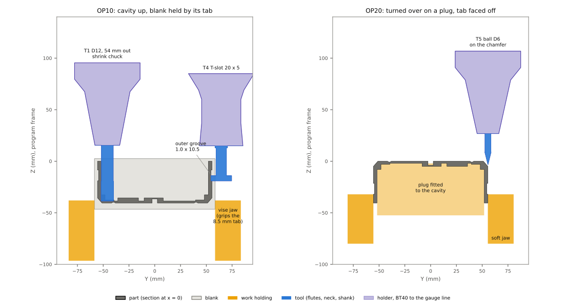
Each value is marked read (the source states it), derived or chosen (the agent's decision).
- Material and machine (chosen). Al 6061-T6; a generic BT40 three-axis machining centre on HiNC's empty skeleton, rapids 25.4 m/min, the FANUC αT12/12000i spindle HiNC ships (12 kW continuous at 6000 rpm, 9.2 kW at 8000, 3.7 kW at 12000); flood coolant. General tolerance ISO 2768-m, so ±0.1 mm on the features that matter.
- Two set-ups per part. OP10 machines the inside from a blank 8–8.5 mm taller than the part, held in a vice by that extra material (the tab). OP20 turns the part over onto a plug made from the cavity — filling only the space reachable from the open side, relieved under every through hole and around the grille — clamps it in soft jaws, faces the tab off and machines the outside, the chamfers, the holes and the countersinks. OP20's stock is OP10's simulated result, exported from HiNC and turned over.
- Tools (read where a catalogue exists). A Ø12 and a Ø6 three-flute long-reach aluminium end mill (RobbJack MFMHV-303-12 and -06: 19.03 mm flutes, neck Ø11.4 to 54 mm; 10 mm flutes, neck Ø5.7 to 40 mm), a Ø20 × 5 T-slot cutter on a Ø10 neck, Ø6 and Ø2 ball ends, Ø2.7 / Ø3.3 / Ø5.1 drills, standard Ø12 and Ø6 end mills for the cover and panels, and a Ø1.5 long-neck end mill (neck Ø1.4 to 12 mm) for the 2.0 mm grille slots. Every tool sits in a BT40 shrink-fit chuck or an ER25 collet chuck, and each stick-out is the shortest that reaches.
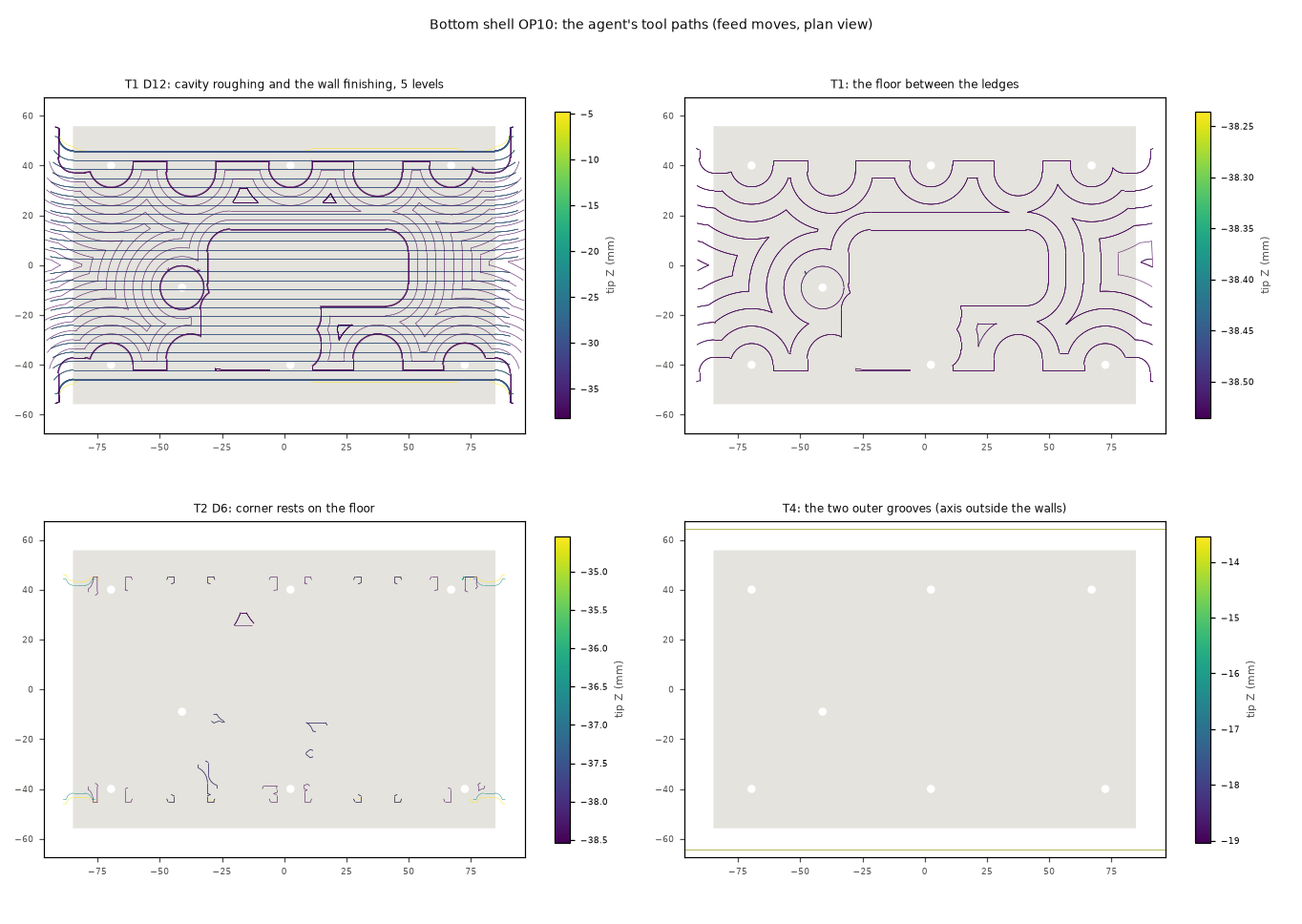
- The agent's CAM. Written for this case in Python (shapely and trimesh): the part sliced into sections, a forbidden region for the tool at each height (the part above that height grown by the tool's radius there — ball, T-slot head, neck, holder nose and fixture included), offset passes far from the part first, strung into chains; a stock model of the blank minus every swept pass, so passes run only where there is material and rapids only where the whole tool clears everything; clearances of the neck, the holder and the whole tool to the part, the stock and the fixture measured on every pass.
Each part's two set-ups as programmed, with the plan's feed time (rapids not included):
| Part | OP10, held by the tab | OP20, turned over | Feed time (min) |
|---|---|---|---|
| Bottom shell | blank 175 × 117 × 49, the vice gripping its lowest 8.5 mm; the top faced; the outside profile roughed and finished, with the 3 mm of stock at each end; the outer grooves with the T-slot cutter; the cavity roughed in five levels, the inner walls finished after each; the flats finished; corner rests with the Ø6; the narrow gap between the two pads with the Ø4 | a plug fitted to the cavity, filling only what the open side reaches and relieved R4 under the through holes, and soft jaws on the wall top; the 6 mm tab faced off; the outside profile finished; the 49° chamfers along both long edges with the Ø6 ball; 7 × Ø2.7, 4 × Ø3.3 and one Ø5.1 (the 1/4-20 tap drill) drilled; the seven countersink cones with the Ø2 ball | 35.5 + 20.4 |
| Top cover | blank 175 × 117 × 24, gripping 4.5 mm; the pocket on the underside; the flanges inside and out, the narrow band beside the flange tops at both ends cut from outside the outline; 8 × Ø3.3 blind holes | plug, and soft jaws on the flanges; the tab faced off; the top plate's 49° outer bevel, roughed with the Ø12 and finished in z-levels with the Ø6 ball, both to −5; the 0.3 mm deep logo, Ø6 then Ø1 | 38.9 + 19.5 |
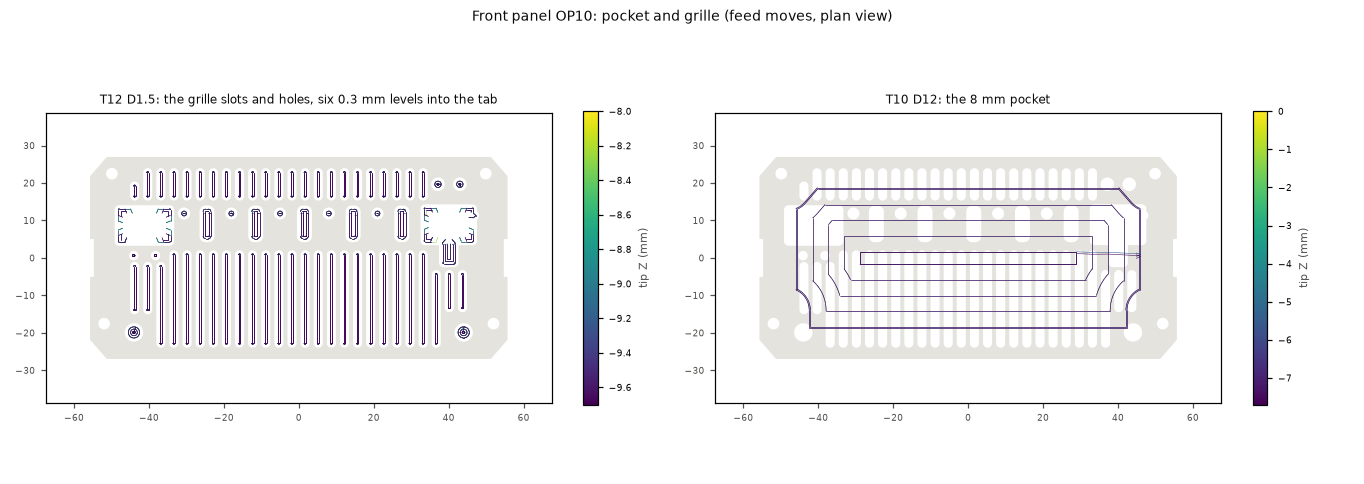
| Front panel | blank 117 × 59.5 × 17.5, gripping 5 mm; the 8 mm pocket; the web's openings cut from the inside through into the tab while the tab still backs the web (Ø1.5, 0.3 mm a level); the end-face notches from outside the outline; 4 × Ø2.7 | a plug relieved 2.2 mm round the grille, and 80 mm soft jaws clear of the ends; the tab faced off; the edge slots the neck rule kept out of OP10, cut through from the outside; the corner holes' four Ø4.7 counterbores with the Ø3; the curved ends, roughed with the Ø12 and finished in z-levels with the Ø6 ball to −6; the countersink cones with the Ø2 ball | 93.5 + 20.1 |
| Back panel | as the front panel | as the front panel | 125.2 + 20.5 |
The fourteen tools, in generic BT40 holders the agent built from their Z–R profiles (shrink-fit chucks with a 4.5° taper, ER25 collet chucks); stick-out in mm, speed in rpm, feed in mm/min:
| Tool | What | Source | Stick-out | Speed / feed |
|---|---|---|---|---|
| T1 | Ø12 three-flute long-reach aluminium end mill: 19.03 mm flutes, neck Ø11.4 to 54 mm | RobbJack MFMHV-303-12-CB catalogue | 54 | 8000 / 1920 |
| T2 | Ø6 three-flute long-reach aluminium end mill: 10 mm flutes, neck Ø5.7 to 40 mm | RobbJack MFMHV-303-06 catalogue | 40 | 12000 / 1080–1440 |
| T3 | Ø4 three-flute end mill, 8 mm flutes | generic | 16 | 12000 / 900 |
| T4 | T-slot cutter Ø20 × 5 on a Ø10 neck, six flutes | generic: the common 20 × 5 on a 12 mm shank | 34 | 6000 / 1080 |
| T5, T6 | Ø6 and Ø2 ball ends | generic | 30, 12 | 12000 / 2400, 600 |
| T7–T9 | Ø2.7, Ø3.3 and Ø5.1 carbide drills, 140° point | DIN 6537 K proportions | 26–34 | 3700–7000 rpm |
| T10, T11 | Ø12 and Ø6 standard-length aluminium end mills, for the cover and the panels | DIN 6527 L proportions | 32, 20 | 8000 / 1920, 12000 / 1440 |
| T12 | Ø1.5 two-flute long-neck end mill: 3 mm flutes, neck Ø1.4 to 12 mm; the grille at 0.3 mm a level | generic | 14 | 12000 / 360 |
| T13, T14 | Ø3 and Ø1 two-flute end mills | generic | 14, 10 | 12000 / 720, 240 |
How the agent managed the work
- Pass criteria first. Seven criteria were written and committed before the first play: every program runs clean (no rapid cut, collision or stroke message); the neck, holder and fixture clearances; the long cutter's deflection on the wall finishing (≤ 25 µm, a quarter of the tolerance) and in roughing (95th percentile ≤ 100 µm); spindle power and tool stress below 1; the finished part against the model at the drawing tolerance; HiNC's time within 15 % of the agent's estimate.
- A trimmed case first. The bottom shell's OP10 was played alone three times at 0.25 mm, with 1 mm checks between, before the whole case was played once for acceptance.
- Every tool must cut. The agent checks the contact of every operation in every play.
- A shared server. The plays ran on a 32-thread server shared with ten other product cases, on a private instance; the acceptance waited for the shared lock that lets one whole-case play run at a time.
- Where a person stepped in. Nowhere during the build. No second agent rebuilt the case or reviewed its claims.
The dilemmas
Every problem the record lists, in its order; the larger ones have a section of their own below:
| # | Problem | Noticed by | Resolution |
|---|---|---|---|
| 1 | Two solids in each panel's STEP file, 53.5 mm tall with the grille and 52.5 mm with one large window | the sections against the drawings | the 53.5 mm solid, the one the drawings show |
| 2 | The wall first read as 3.5 mm thick below 21 mm and 2.5 mm above | redrawing the wall's section | 3.5 mm over the full height, 2.5 mm only where the outer groove runs |
| 3 | The outer groove undercuts the wall: the wall top above it stands 1 mm proud of the groove's floor | rays from every face, up and down | the T-slot cutter from the outside in OP10, while the cavity is uncut and the wall still backed |
| 4 | 24 R1 inner corners 38 mm deep and 4–7 mm from the walls: a Ø2 would need 40 mm of stick-out, 20 times its diameter, and its holder would not pass | rest-material analysis | the Ø6 leaves R3, recorded as planned stock and put to the designer |
| 5 | A 72.6° countersink cone, Ø6.2 to Ø2.7 (Ø4.7 to Ø2.7 on the panels), where the fastener list names 90° ISO 7046 screws | the cone's face normals | the Ø2 ball follows the cone level by level, as modelled |
| 6 | Four M2.5 holes along X in the end faces of the shell and the cover | ray reachability | not made, and listed: two vertical set-ups cannot reach them |
| 7 | The first plug also filled the blind holes opening on the other side, so the drills went 3–5 mm “into the fixture” | the agent's fixture clearance check | the plug fills only what the open side reaches |
| 8 | Every entry ramped down from the blank's original top, +2.46, to the cavity floor: a 76-minute program, most of it in the air | the program's length, broken down | ramps start at the stock actually left within the pass; later, sideways lead-ins |
| 9 | The length offset outlived the tool change: G43 H1 stayed active for the next tool, the wrong length on a machine |
HiNC's Comp-ToolHeight--HOutlivesToolChange |
G91 G28 Z0 and G49 before every change |
| 10 | Rapids into stock: the outside profile's level missed the 3 mm left at the X ends, and a lead-in point there counted as air | HiNC's Play-RapidCut--Detected, 19 and 14 mm³ |
the outside profile round the whole outline; lead-ins that do not enter stock; rapid descents only where nothing lies within the cutter's radius + 0.3 mm |
| 11 | The FANUC αT12/12000i gives 12 kW at 6000 rpm but 3.7 kW at 12000: the roughing's full-width entries asked 3.3 times the continuous rating | HiNC's spindle power ratio | the Ø12 at 8000 rpm (9.2 kW), links at 40 % feed, ramps at 50 %, 9.6 mm levels |
| 12 | A 19 mm tall finishing pass bent the Ø12 57 µm, the Ø6 rests up to 155 µm: more than a quarter of the ±0.1 mm tolerance | HiNC's tip deflection | walls finished in 6 mm steps; the Ø6 rests in 2 mm levels at a lower feed |
| 13 | The Ø1.5's Ø1.4 neck passed 0.05 mm from a tall wall in a pocket corner | the agent's neck clearance check | the forbidden region adds the neck's and shank's radius + 0.22 mm, against part and stock; the edge slots it blocks are cut from outside in OP20 |
| 14 | Rapids that graze finished walls: a rapid descent on the wall's tool radius, a retract straight up at a finish's end, a 1.0 mm lead-in equal to the stock left at the X ends | HiNC: rapid cuts of 0 to 5·10⁻¹³ mm³, with deflection spikes of 137 and 274 µm on the same steps | a 1.2 mm sideways lead-in and lead-out on every finishing pass |
| 15 | A drill moved before its length offset: after the change, G00 Z25 came before G43 H7, so the tip went about 90 mm down into the stock and the vice |
HiNC's first acceptance play: 42 collisions and 59 Z-stroke overruns at the end of each panel's OP10 | no Z move before G43; five programs lose one line each |
| 16 | The Ø1.5 grille cutter, in levels of 0.75 and 0.95 mm, bent 144 µm at the 95th percentile and 177 µm at most, at a stress ratio of 0.88 | the front panel's first staged acceptance play | a step-down trial at a 0.05 mm cell: 134, 91, 55 and 36 µm at 0.75, 0.5, 0.3 and 0.2 mm, about 180 µm per mm; 0.3 mm levels, six from each side |
| 17 | Two areas no pass reached on the cover: the lower half of the 5 mm tall 49° bevel, roughed to −3 and finished to −2.1, up to 1.3 mm left; a 2 mm band beside a lug at both ends, 2.8 mm left | the exported cover against the model: 95.8 % within the limit | the bevel roughed and finished to −5; the band cut from outside the outline |
| 18 | The panels' curved ends and an end-face notch short: corners reaching −5.7 cut only to −2.6 / −2.7, a 1.8 × 5.6 mm notch on the outline; 1.4 and 2.0 mm left (98.0 %); cut to −7.3, the Ø6 ball came within 0.44 mm of the 100 mm soft jaws | the exported panels against the model; the agent's fixture clearance check, which asks 2.0 mm | the ends roughed and finished to −6.0, the cone below being the Ø2 ball's countersink; the notch cut from outside the outline; the soft jaws shortened to 80 mm, clearing 15 mm at each end |
Two solids in each panel file
Situation. The front and back panel STEP files each hold two solids, 53.5 and 52.5 mm tall, 0.5 mm apart. Risk. Machining the wrong one. Noticed on loading the files. Resolution. The 53.5 mm solid is the one the drawings show (the 2.0 mm grille, the four corner holes); the other has one large window where the grille is and looks like a body simplified for the thermal simulation the README describes. Evidence. The drawings' outline and hole pattern match the 53.5 mm solid.
A groove that undercuts the wall
Situation. The bottom shell's walls carry a 1.0 × 10.5 mm groove along the outside, below the wall top. Risk. Seen from above, the wall top hides the groove: two vertical set-ups cannot make it with an end mill. Noticed by casting rays from every face up and down. Resolution. A Ø20 × 5 T-slot cutter on a Ø10 neck cuts it from the side in OP10, while the cavity is still full and the wall is backed by stock. Evidence. The finished shell, compared with the model, holds no stock beyond the limit in either groove.
Deep corners of 1 mm radius
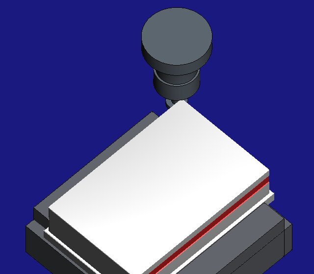
Situation. Twenty-four inner corners at the roots of the tongues and pads, 38 mm deep and 4–7 mm from the walls, have a 1 mm radius. Risk. A Ø2 end mill would need a 40 mm stick-out (20 times its diameter) and its holder would not clear the wall. Resolution. The Ø6 cutter leaves them at R3; the case records them as planned rest material and the report asks the designer whether R3 would do. Evidence. The finished shell shows them as the only stock left inside the cavity: 0.41 to 0.98 mm on the corner bisector, as an R3 in an R1 corner leaves.
A countersink angle no standard tool has
Situation. The corner and panel holes are countersunk with a 72.6° cone (Ø6.2 to Ø2.7 on the shell), while the fastener list names ISO 7046 screws, which have a 90° head. Risk. A standard 90° countersink tool cuts a cone the model does not have. Resolution. A Ø2 ball end follows the cone level by level, as modelled; the mismatch is reported to the designer. Evidence. The seven cones of the shell come out within the limit; the Ø2 ball, 12 mm out of its chuck, bends 17 µm (95th percentile) on them.
A plug that filled the blind holes
Situation. The first OP20 plug was the cavity itself. Risk. It also filled the blind holes, which open on the other side, the floor's outer face, so the drills went 3–5 mm “into the fixture”. Noticed by the agent's own fixture clearance check. Resolution. The plug occupies only what is reachable from the open side, relieved R4 under every through hole and 2.2 mm round the grille. Evidence. The nearest tool to the fixture in the shell's OP20 is 2.1 mm (the Ø3.3 drill at the bottom of a blind hole); no play reports a collision with the fixture.
A spindle that is weak where the small tools run
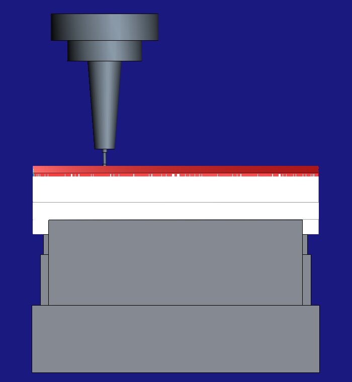
Situation. The αT12/12000i gives 12 kW at 6000 rpm but 3.7 kW continuous at 12000. Risk. The Ø12 cutter's first program at 12000 rpm asked for 3.3 times the continuous rating in full-width entries. Noticed in HiNC's spindle power ratio on the first trimmed play. Resolution. The Ø12 runs at 8000 rpm (9.2 kW), links between passes at 40 % feed and ramps at 50 %, 9.6 mm levels. Evidence. The highest ratio in the whole acceptance is 0.79, in the shell's cavity roughing; the cover's highest, 0.67, comes in the finish of its outside profile.
The long cutter bends on a tall finishing pass
Situation. One finishing pass 19 mm tall with the Ø12 long-reach cutter bent it 57 µm; the Ø6 cutter's rest passes bent up to 155 µm. Risk. More than the wall's tolerance allows. Noticed in HiNC's tip deflection. Resolution. Walls are finished in 6 mm steps at every roughing level; the Ø6 rests in 2 mm levels at a lower feed. Evidence. In the acceptance the wall finishing stays within 22 µm at the 95th percentile on every part; its maxima, 31 to 43 µm (the shell's and the cover's OP10 replayed on HiNC 3.2.45 for the NC-optimization study), come where a finishing pass engages more than its 0.3 mm allowance (stock at the open ends, corners).
A neck that rubs
Situation. The Ø1.5 cutter's neck is Ø1.4; in a pocket corner its neck passed 0.05 mm from a tall wall. Risk. A neck that rubs breaks a Ø1.5 tool. Noticed by the agent's neck clearance check. Resolution. The forbidden region adds the neck's and shank's radius plus 0.22 mm, against the part and the uncut stock; the grille slots at the panel's edge that this rule blocks are cut from the outside in OP20. Evidence. The nearest neck to the part or the stock in the acceptance is 0.22 mm (a Ø6 rest pass on the cover) and the Ø1.5's is 1.04 mm; HiNC, which checks holder and shank against the stock, reports no collision in any accepted play.
Rapid moves that graze a finished wall
Situation. Finishing passes started on the tool radius of the wall and the tool came down there at rapid; later plays showed two more of the kind: a retract straight up from the end of a finishing pass, and a lead-in point whose 1.0 mm offset equalled the stock left on the part's ends, so the descent ran tangent to that stock. Risk. The tool's edge brushes a finished wall at rapid feed. Noticed in HiNC: rapid cuts of 0 to 5·10⁻¹³ mm³, with deflection spikes of 137 and 274 µm computed on the same steps. Resolution. Every finishing contour now starts and ends 1.2 mm off the wall: the tool comes down in the free space, feeds in sideways, and at the end feeds away from the wall before it lifts; rapid descents only where the tool clears everything by its radius plus 0.3 mm. Evidence. No accepted play reports a rapid cut, and the deflection spikes are gone.
A grille cutter that bends more than the slot's tolerance
Situation. The 2.0 mm grille slots are cut with a Ø1.5 two-flute end mill, 14 mm out of its chuck, through the 1.5 mm web in two levels of 0.75 and 0.95 mm. Risk. Slot walls out of their ±0.1 mm, and a broken Ø1.5 cutter. Noticed in the first staged play of the front panel: the cutter's tip deflection reached 144 µm at the 95th percentile and 177 µm at most, at 0.88 of the tool's yield stress. Resolution. The agent played a trimmed case: the same cutter, speed and feed slotting solid stock at four step-downs, at a grid finer than the smallest of them.
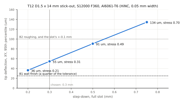
The deflection follows the step-down almost in proportion, about 180 µm per millimetre (134, 91, 55 and 36 µm at 0.75, 0.5, 0.3 and 0.2 mm). The programs now cut the openings in 0.3 mm levels, six from each side. Evidence. In the acceptance the Ø1.5 bends 62 µm at the 95th percentile and 98 µm at most, its stress peaking at 0.53 of its yield stress; it costs time: the front panel's grille takes 88 minutes instead of 34, the back panel's 120 instead of 40.
Two places no pass reached on the cover
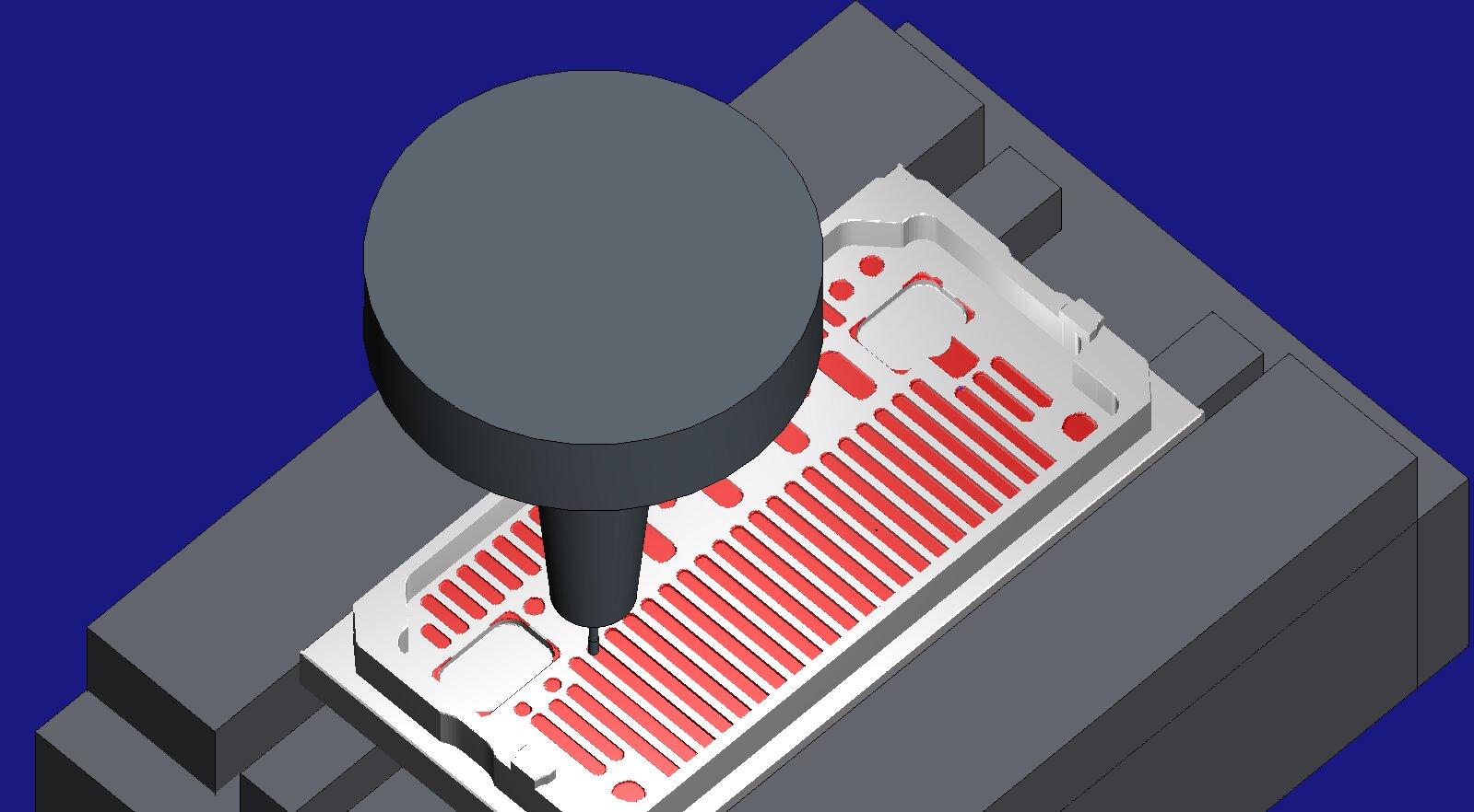
Situation. The first accepted play of the top cover finished clean, and its finished part against the model still showed two areas of stock: the lower half of the top plate's 49° outer bevel, which is 5 mm tall where the agent's program had roughed to 3 mm and ball-finished to 2.1 mm; and, at both ends, the flange tops beside a 1.5 mm lug, a band 2 mm wide between the lug and the outline, too narrow for any tool inside the outline. Risk. A part that is not the drawing, with up to 2.8 mm of stock where the design is open. Noticed in the comparison of HiNC's exported part with the model: 95.8 % of the surface within the limit instead of the 99 % the other parts reached, in two long strips and four corners. Resolution. The bevel is roughed and ball-finished down to 5 mm; the flat beside the lug is cut from outside the outline, the cutter's edge reaching in while its centre stays in the open. Evidence. The cover's re-play is 99.6 % within the limit, the rest drill points in blind holes and inside corners. The same check then found the panels' curved ends and an end-face notch short in the same way (98.0 %); fixed alike, they reach 99.4 %.
A drill that moved before its length offset
Situation. Each drilling operation began with a retract to its clearance height, and after a tool
change that retract came one line before G43: without the length offset, Z25 places the spindle
nose, not the tip, and the drill went about 90 mm down. Risk. A crash into the part and the vice
on the first hole. Noticed in HiNC's first acceptance play of the panels: 42 collisions of the
drill with the vice and of its holder with the part, and 59 Z-stroke overruns, all in the last
operation. Resolution. The CAM emits no Z move between a change and the G43 line, which brings
the tool to clearance height itself; five programs lost one line each. Evidence. No accepted play
reports a collision or a stroke overrun.
Results and benefits
Measured on HiNC 3.2.43 at a 0.25 mm cell with one step per spindle turn. Each set-up was played one tool per run, the stock handed on between runs (the shell's OP20 in one run). The agent's estimate is its feed time plus rapids at 25.4 m/min.
| Set-up | Agent's estimate (min) | HiNC (min) | Steps | Server time (min) |
|---|---|---|---|---|
| Bottom shell OP10 | 37.5 | 37.7 | 320,360 | 12.7 |
| Bottom shell OP20 | 21.6 | 21.8 | 243,197 | 33.4 |
| Top cover OP10 | 39.6 | 39.7 | 323,300 | 8.3 |
| Top cover OP20 | 20.4 | 20.6 | 226,952 | 16.1 |
| Front panel OP10 | 94.0 | 94.1 | 1,131,858 | 10.3 |
| Front panel OP20 | 21.3 | 21.5 | 258,794 | 4.1 |
| Back panel OP10 | 125.4 | 125.6 | 1,493,571 | 8.5 |
| Back panel OP20 | 21.7 | 21.9 | 264,013 | 3.8 |
| Total | 381.5 | 382.9 | 97.1 |
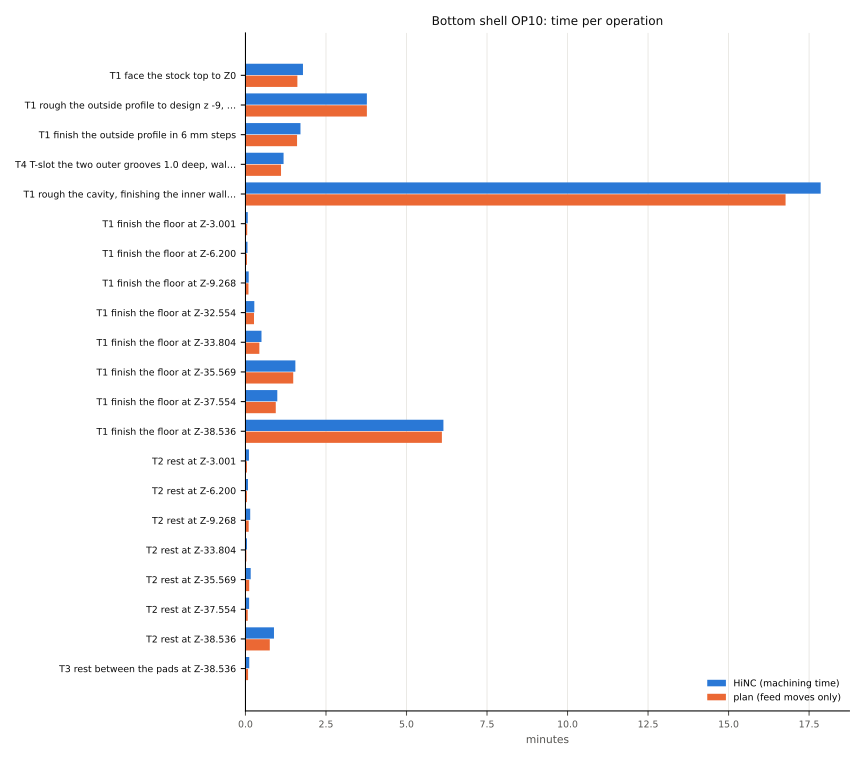
The shell's OP10 operation by operation: HiNC in blue, the plan's feed time in orange. The cavity roughing takes almost half of the set-up's 37.7 minutes.
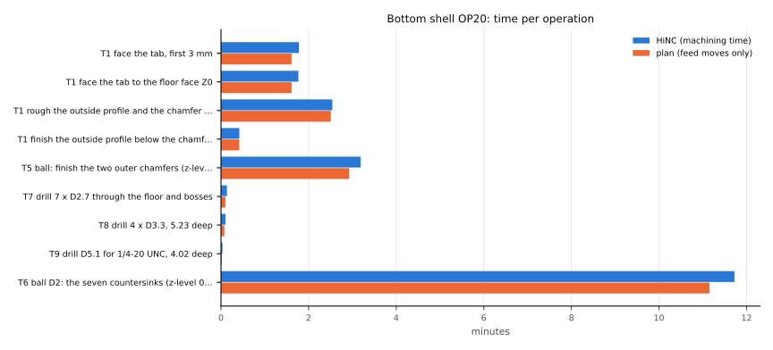
The shell's OP20: the countersink cones, followed level by level with the Ø2 ball, take more than half of the 21.8 minutes.
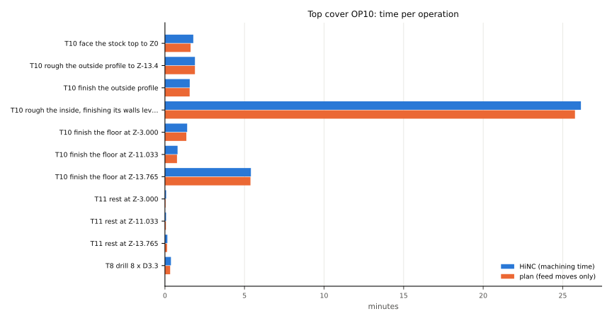
The cover's OP10: the inside roughing takes two thirds of the 39.7 minutes.
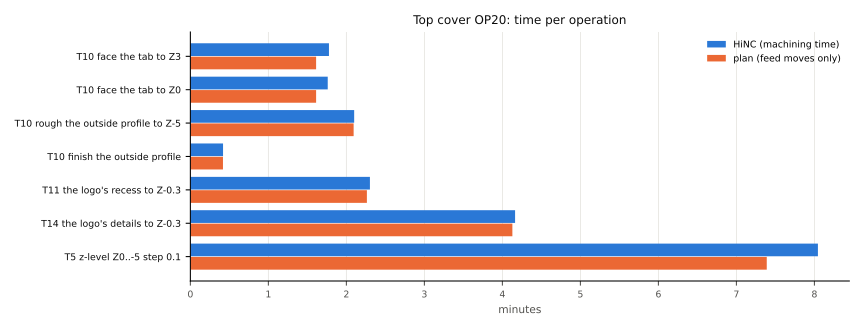
The cover's OP20: the Ø6 ball's z-level finish of the 49° bevel, now down to its full 5 mm, is the longest operation.
| Criterion | Bottom shell | Top cover | Front panel | Back panel |
|---|---|---|---|---|
| Every program runs to the end with no rapid cut, collision or stroke overrun | pass | pass | pass | pass |
| Agent's clearance check: neck ≥ 0.2, holder ≥ 1.0, whole tool to fixture ≥ 2.0 mm | pass (0.27 / 25.6 / 2.1) | pass (0.22 / – / 5.5) | pass (0.67 / – / 2.3) | pass (0.67 / – / 2.2) |
| Long cutter on a finishing pass ≤ 25 µm at every step | fail: 95th pct ≤ 20 µm, max 42.6 µm (OP10, replayed on HiNC 3.2.45); OP20 Ø6 ball chamfer 35 / 40 µm | fail: 95th pct ≤ 22 µm, max 36.5 µm (OP10, replayed on HiNC 3.2.45); OP20 bevel 28 µm | fail: 95th pct ≤ 17 µm, max 34 µm, curved ends 56 µm | fail: 95th pct ≤ 17 µm, max 31 µm, curved ends 56 µm |
| Roughing deflection, 95th percentile ≤ 100 µm | pass (52 µm, OP10 replayed on HiNC 3.2.45) | pass (22 µm, OP10 replayed on HiNC 3.2.45) | pass (62 µm, Ø1.5) | pass (62 µm, Ø1.5) |
| Spindle power ratio and stress ratio ≤ 1 | pass (0.79, 0.47) | pass (0.67, 0.56) | pass (0.43, 0.78) | pass (0.43, 0.78) |
| Finished part within 0.1 mm + half a cell (0.225 mm) of the model, except planned stock | pass (99.34 %) | pass (99.56 %) | pass (99.39 %) | pass (99.42 %) |
| HiNC's time within ±15 % of the estimate | pass (+0.6 / +0.8 %) | pass (+0.3 / +0.9 %) | pass (+0.2 / +1.0 %) | pass (+0.1 / +1.0 %) |
- The failed criterion. The finishing passes leave 0.3 mm. Where a pass meets more than that, the steps bend past 25 µm: at the open ends, at corners, and on the panels' curved ends with a ball. Only the shell's Ø6 chamfer is past it at the 95th percentile too. Every value stays inside the ±0.1 mm general tolerance; the criterion asked for a quarter of it.
- What the comparison leaves. The “gouges” are all drill points: the models draw the blind holes
flat-bottomed, and a 140° drill is about 0.5 mm deeper at its centre. The planned stock is:
- the R3 left in the R1 corners, 0.41 to 0.98 mm on the bisector;
- the four end-face holes;
- the ball's cusps under the chamfers, about 0.3 mm.
- Run cost. The plays took 97 minutes of a 32-thread server for 6.4 hours of machining. The shell's OP20 took longest because HiNC builds a stock given as a 1.58-million-triangle mesh on one thread. The private instance peaked at 34 GB of resident memory over the whole case, trimmed plays included; which play set the peak was not recorded.
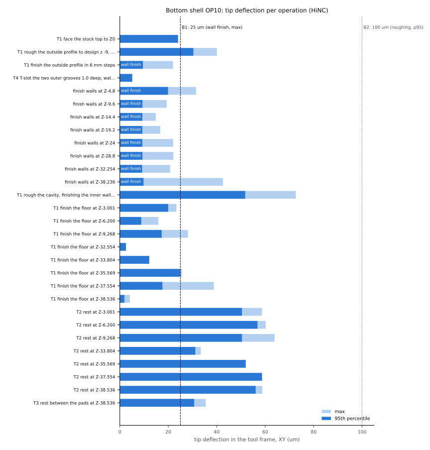
The shell's OP10: every wall-finishing level stays within 20 µm at the 95th percentile; the largest steps, up to 42.6 µm on the deepest level, come where a pass meets more stock than its allowance. The program replayed whole on HiNC 3.2.45 for the NC-optimization study, over its cutting steps.
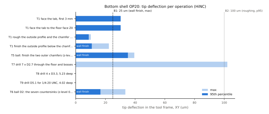
The shell's OP20: the Ø6 ball on the chamfers is the one finishing pass over 25 µm at the 95th percentile, 35 µm; the Ø2 ball on the countersink cones bends 17 µm.
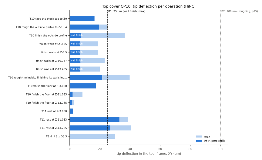
The cover's OP10: every wall-finishing level stays within 8 µm at the 95th percentile; the outside profile's finish reaches 36.5 µm at its largest step, where it meets the stock at the open ends. The program replayed whole on HiNC 3.2.45 for the NC-optimization study, over its cutting steps.
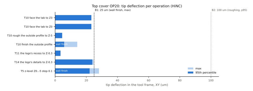
The cover's OP20: the bevel's z-level finish bends 22 µm at the 95th percentile and 28 µm at most.
What the numbers give a machining engineer:
- Times per part: 59.5 minutes for the shell, 60.3 for the cover, 115.6 and 147.5 for the front and back panels. On the panels the grille is the larger share: 88 and 120 minutes.
- A step-down rule for the Ø1.5 cutter: about 180 µm of bending per millimetre.
- What would have gone wrong on the machine, found before any cut: the drill crash, the overloaded spindle, the grazing rapids, the bending cutters, and four areas the programs never reached, two on the cover and two on each panel.
For a teacher or student, the case is a complete two-set-up plan for a thin-walled housing:
- an undercut reached from the side while the wall is still backed;
- a plug that leaves the blind holes open;
- a neck clearance kept against the stock that is still standing;
- the order in which HiNC's checks found each problem.
For someone weighing whether the approach is worth using: an agent with no program to start from wrote one, and HiNC's per-operation loads, contact counts and exported part took it to a set of programs that pass six of seven criteria written in advance.
Honest limits
- The walls are rigid. HiNC reports the tool's bending, not the 3.5 mm wall's; how far a 38.5 mm wall gives under the finishing cutter, and whether it chatters, is outside the simulation.
- Clamping is geometry only. The vice, plug and soft jaws are checked for collisions; clamping force, the part's movement on the plug and vibration when the tab is faced off are not simulated.
- What two vertical set-ups cannot make. The four M2.5 holes in the end faces of the shell and cover run along X and are left out; the R1 corners are left at R3.
- The cutting data are generic. Where a catalogue gives a tool its geometry is read from it; the rest, the holders and the spindle are generic; Al 6061-T6 stands in for an unnamed alloy. Loads are HiNC's model, not measurements.
- Distortion and finish. Residual stress after removing most of the blank, anodising and surface finish are not simulated.
- No blind build, no review. No second agent rebuilt the case from its record or checked its claims.
What a reader can take to their own case
- Look for undercuts before choosing set-ups. A ray from every face up and down shows what two vertical set-ups can reach; a groove under a wall top needs a side cutter while the wall is still backed.
- Build the plug from what the open side can reach. A plug made from the cavity fills blind holes and slots; accumulate it from the open side and relieve it under every hole.
- Read the spindle's power curve, not its top speed. A small cutter at the spindle's top speed may ask for more than the spindle gives there; the power ratio shows it on the first play.
- Finish tall walls in steps. A long cutter's bending grows with the engaged length; finishing each roughing level keeps it inside the tolerance.
- Keep the neck off the walls. A long-neck cutter's neck needs its own clearance, against the part and the stock still standing.
- Count the contact of every operation. A play that finishes is not a play that cut; an operation with no contact is a finding, whatever its cause.
Source and licence
- Source: Antmicro, Enclosure for Antmicro baseboard with NVIDIA Jetson AGX Thor,
https://github.com/antmicro/jetson-agx-thor-baseboard-enclosure (branch
main, read 2026-09-30). Search terms if the link moves:antmicro jetson-agx-thor-baseboard-enclosure,cnc-milled-bottom-shell-al. - Licence: Apache License 2.0. The README states “Copyright (c) 2026 Antmicro” and “This project is published under the Apache-2.0 license.” The licence gives the material as is, without warranty.
- Attribution: “Enclosure design (c) 2026 Antmicro, Apache-2.0, https://github.com/antmicro/jetson-agx-thor-baseboard-enclosure. Machining set-up by Tech Coordinate's agent (changes: stock, fixtures, toolpaths).”
- Changed from the original: the part models are used unchanged; the stock, the fixtures (vice and tab, plug and soft jaws), the tools and holders, the two set-ups per part and their programs are the agent's. The NVIDIA product name is used only to say what the enclosure fits.
See Also
- Jetson AGX Thor Enclosure, Optimized — HiNC's feed optimization on this case: 28 to 52 % off the long-cutter set-ups, the cover's finishing bend held within 25 µm, and 37 % off the grille
- Showcase — the other cases and how a case page reads
- Replay Acceptance over the HTTP API — watching a play and accepting on evidence
- Cutter Geometry — holder profile, neck and stick-out