The cubic machining test with the eight rotary-axis errors a ball bar measured: zones II and III stand 0.43 and 0.23 µm above zone I, a 10 µm tool-length error moves them 1.34 µm, and a calibrated controller still leaves 0.05 µm (5-axis)
- Original source
- Z. Li, H. Ogata, R. Sato, K. Shirase, S. Sakamoto, Influence of Tool Length and Profile Errors on the Inaccuracy of Cubic-Machining Test Results, Journal of Manufacturing and Materials Processing 5(2), 51 (2021), MDPI — DOI 10.3390/jmmp5020051. The article publishes no data set, NC program or model ("The data presented in this study are not available."). The case uses its printed numbers: the machine type, the test piece and the cutting conditions of Section 2 and Table 1, the eight errors of Table 5, the tool-length formula of Eq. 2, and the measured and simulated zone heights of Figs. 7 and 11 and Tables 3 and 6.
- Search keywords
jmmp5020051,Influence of Tool Length and Profile Errors on the Inaccuracy of Cubic-Machining Test Results- Licence
- The article is under Creative Commons Attribution 4.0 International (CC BY 4.0), as its first page states: "Copyright: © 2021 by the authors. Licensee MDPI, Basel, Switzerland. This article is an open access article distributed under the terms and conditions of the Creative Commons Attribution (CC BY) license (http://creativecommons.org/licenses/by/4.0/)." It comes without warranty. The case takes the article's numbers only. This page reproduces no picture from the article: every picture is a HiNC capture or a chart drawn from HiNC's results and the article's printed numbers.
- Attribution
-
As the case's source record gives it:
Measured data, errors and test conditions: Z. Li, H. Ogata, R. Sato, K. Shirase, S. Sakamoto,
"Influence of Tool Length and Profile Errors on the Inaccuracy of Cubic-Machining Test Results",
J. Manuf. Mater. Process. 5(2), 51 (2021), https://doi.org/10.3390/jmmp5020051. © 2021 by the authors,
licensee MDPI, Basel, Switzerland. Licensed CC BY 4.0 (https://creativecommons.org/licenses/by/4.0/),
provided as-is without warranties. Changes: the part model, the NC program, the machine and the HiNC
project are ours, built from the article's description (see "What we changed").
What we changed, in short: a generic B/C table-table machine, not the article's; a 48 × 48 × 30 mm block on a 70 mm riser; an NC program written from the article's description, with the zone order and the moves between zones chosen and the zero-depth pass left out; the cutter's unstated lengths, its stick-out and the holder chosen.
Tech Coordinate's agent put the eight Table 5 values into two error-term branches on the simulated machine and chose the point they turn about, their sign convention and the touch-off. The authors and MDPI do not endorse Tech Coordinate, HiNC or this case. - About the case
- Li and colleagues ran the cubic machining test on a five-axis machining centre whose C
rotary table rides on a B tilting table (a DMG Mori NMV 1500 DCG). One 48 × 48 mm face is split into
3 × 3 zones: zone I cut with the tool vertical, the four zones II with it tilted 30° toward the centre,
the four zones III tilted 30° and turned 45°, all by an R3 ball-end mill under TCP; the test reads each
zone's height against zone I over the central 40 × 40 mm. A ball bar identified eight location and
orientation errors of the two rotary axes (Table 5), from which the authors simulated −1.4 to +0.9 µm
(Fig. 11a); they measured +4.4 to +6.1 µm (Fig. 7a) and put the difference down to the ball's edge
profile, about 4 µm off between 0° and 30° (Fig. 13). They also set the controller's tool length 10 µm
long and 10 µm short: under TCP a 30° zone then moves (1 − cos 30°)·eL against zone I (Eq. 2). The
article publishes only numbers, so the agent built the base project itself: a generic B/C table-table
machine, an AA7075 block whose finished face sits at the height where the B and C axis lines cross,
centred on C, the nine zones as one Fanuc
G43.4program of 2,940 lines, and the article's DLC2MBR0300 cutter in a chosen shrink-fit holder. A 1 mm play accepted it.
The story
The cubic machining test shows a five-axis machine's rotary-axis errors on a simple part: each tilted zone is cut by the same ball at another pose, and any error of the axes raises or lowers it against the zone cut upright. What do the eight errors the ball bar measured do to the zones when the controller does not know them? What does a 10 µm tool-length error add? And does a controller that knows the errors, one with calibrated kinematics, cut the nominal part again?
An AI agent put the eight errors into the machine as two error terms, each on a branch of its own just before an axis's branch, marked as an error term. The B axis line's three offsets and three angles went in as one General Transform, a rotation and a translation in one branch, just before B (BY-Table5); the C axis's angle and offset against B as another just before C (CB-Table5). Both turn about the point where the nominal B and C lines cross, which is program zero; the article gives no reference point, so that was the agent's choice. HiNC's controller computes the machine coordinates as if the marked branches were not there, while the simulated machine moves and cuts with them whenever the project's Enable Error Terms switch is on, like a real machine whose controller does not know its errors. A touch-off at B = C = 0 would find program zero moved by the errors, to (11.700, −10.996, −0.647) µm. HiNC's P0 measures the machine as designed, so the runs with the errors typed that offset in by hand, as HiNC's manual advises for reproducing a shop's cut. The tool-length error is no error of the machine but the length the controller holds, so it went in as an axial wear of ∓0.010 mm, with the error terms off.
Before the first play, the agent committed a plan with the tool-tip offset it expected at every step, the height change of every zone's face, and twelve pass criteria. Four runs at 1 mm checked the build; then the whole part played six times at 0.25 mm, geometry only:
- error terms off: the nominal cut, which every comparison is measured against;
- off again, with HiNC's geometry difference (Diff) against the nominal cut: the noise floor;
- on, with the errors marked, so the controller does not know them;
- on, with the marks cleared, so the controller knows them, as calibrated kinematics would;
- error terms off, with the controller's tool length 10 µm too long, and once 10 µm too short.
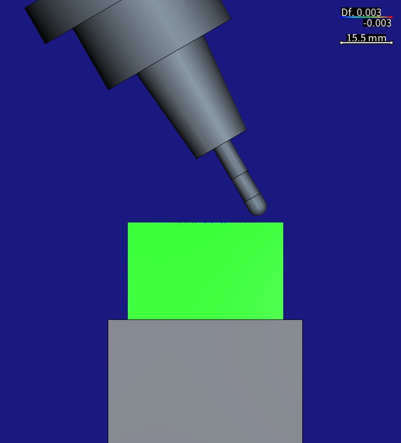
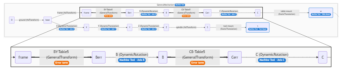
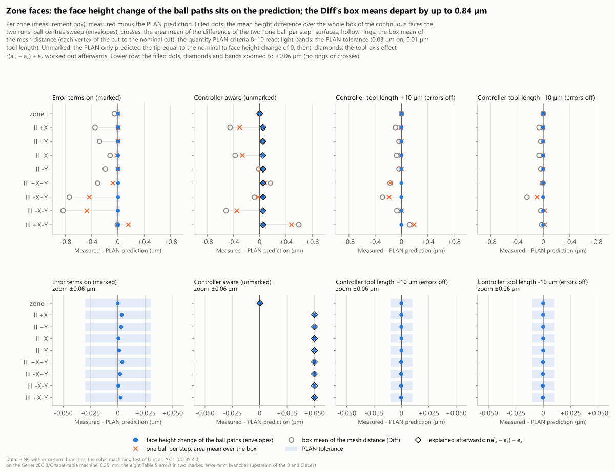
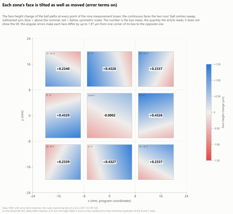
HiNC rendered these pictures on the generic machine with the two error-term branches the agent built in; the part and the program are the agent's, from the article's description. The colours are HiNC's geometry difference (Df in the colour bar) against the part the nominal run cut, on a symmetric scale of ±0.003 mm (±0.012 mm for the tool-length picture): red = cut too deep, blue = material left, green = 0. The cut parts were put back on the canvas with their Diff, not replayed; for the first picture, a parking program brought the cutter into view. The grid is 0.25 mm. The charts are drawn from HiNC's per-step results, the meshes of the cuts it exported and, for the article's values, the numbers the article prints.
| Key number | What it is |
|---|---|
| 7.4×10⁻¹² mm | the largest gap, over the 74,661 TCP steps of the run with the errors, between the measured tool-tip offset and the prediction written before the first play, d = W⁻¹W₀(P + g) − P. On the cut face the tip moves up to 35.0 µm sideways and at most 1.52 µm up or down |
| +0.433 · +0.234 µm | zones II and III against zone I, as the face the ball paths sweep, the four zones of a kind within 0.0003 µm of each other and within 0.004 µm of the prediction. δx_BY alone, the B axis 2 µm off along X, gives +1.000 µm; β_BY takes 0.464 / 0.657 µm off and δz_BY another 0.087 µm; with the part placed as here, the other five errors move a zone by 0.001 µm or less |
| 1.97 µm | how far a zone's face tilts from one corner of its box to the opposite, mostly through γ_BY and α_CB, which move the zone means by 0.0007 µm or less: a test that reads zone means cannot see it |
| 1.340 µm | the tilted zones against zone I with the controller's tool length 10 µm too long (lower) or too short (higher): (1 − cos 30°)·eL, met within 0.00024 µm. The article's Table 6 gives 1.3 to 1.4 µm |
| 5.85 nm · 0.050 µm | with the marks cleared, as a calibrated controller: the tip's constant offset from the program, a second-order term of the typed touch-off, and the tilted faces still standing high, because under G43.4 the tool's direction keeps the errors' rotation |
| 4.63 µm | the ridge between two steps 1/3 mm apart: the simulation places one ball per spindle revolution and does not sweep between steps. HiNC's Diff box means read these ridges and miss the face height by up to 0.84 µm |
| 6 of 12 | the plan's criteria that failed as written, each cause measured: rows of 48 or 49 steps, 143 steps outside the TCP section, the ridges, and the unmarked run's 5.85 nm. None of them is an error of the error terms or of the predictions |
| 90 s · 1.506 GiB | server time and the heaviest peak memory of a whole-part run on the shared 32-thread server; ten runs in all, four at 1 mm and six at 0.25 mm |
Four of its nine dilemmas
Where the part sits, and about which point the errors turn
Where the B and C axis lines, the table and the part of the article's machine sit is in another article of the authors, not open access, and Table 5 does not say about which point its angles turn. An angular error moves the part by its angle times the lever from its pivot, so another placement changes both the size and the pattern of the zone heights. The agent wrote one placement into the plan that can be stated plainly: the part centred on C, its face at the height where the B and C lines cross, both errors turning about that point. Its cost is written down too: placed so, five of the eight errors only shift the part sideways or have no lever, 0.001 µm or less each on a zone mean, and the result is symmetric. It cannot reproduce the asymmetry of the article's simulation, and compares with it only qualitatively.
A General Transform turns, then translates
The batch's tools first assumed that a General Transform translates and then turns, and the first touch-off offset was computed that way: (11.704, −10.996, −0.648) µm. The check the plan asked for before any play caught it. With the marks cleared, HiNC's P0 read (11.69999934, −10.99644, −0.64732) µm, the value of a turn first and a translation after; translating first would have been 0.004 µm off in x. A typed offset 4 nm off would only have moved the predictions a little, but the wrong order would have spoiled every prediction that uses a General Transform. Before the first play, the prediction was changed to turn first, the typed offset became its value, within 2.9×10⁻¹⁵ mm of P0, and the predictions were recomputed and committed with the plan.
The Diff's box means read the ridges, not the face
The run's motion resolution places one step per spindle revolution, every 10 ms at 6000 rpm, and HiNC does not sweep the ball between steps: steps 1/3 mm apart leave 4.63 µm ridges. Where the two runs' balls sit at different places along a row, the Diff swings by about ±5 µm from vertex to vertex, ten to twenty times the 0.23–0.43 µm to be judged, and the plan judged zone heights on the Diff's box means. They sat up to 0.84 µm off the prediction. The plan had not estimated the ridge height, f²/8R, before writing its criteria. The analysis computed the face the ball paths sweep from the per-step series instead: within 0.0040 µm of the prediction. Where every row has the same step count in both runs, the mean over one ball per step meets it within 0.0027 µm.
The calibrated controller does not cut the nominal part
The plan predicted that with the marks cleared the tip would equal the
nominal one. It came back to the program but for a constant 5.85 nm: the typed touch-off was
found at B = C = 0, and the controller adds it in the table's frame without turning back the two
errors' rotation there, a second-order term of the size of |g| × 0.021154° = 5.93 nm. And the
tilted faces still stood +0.0500 µm high. Under G43.4 the program commands B and C
as numbers, so the calibrated controller puts the tip back on the program point while the tool's
direction on the part keeps the errors' rotation, and the ball's lowest point rises by
r(a′z − az) = 0.0497 µm, the same in every tilted zone. Measured +0.049985 to +0.050065 µm
against the model's 0.050051 µm.
The full record has the other five: which way Table 5's signs go, where a literal reading of the article's Eq. 4 turns every zone height over; rows of 48 or 49 steps, as a 16 mm row at 2000 mm/min lasts exactly 48 spindle revolutions, so the runs were paired by their place along each row; the 143 steps outside the TCP section, each piece with a rule of its own; the plan's box prediction following one ball while the measurement reads one place; and the block's edges, which read up to 8.6 µm in the mesh distance where the two meshes represent the 90° edge differently.
The result
All ten plays ran to the end with no collision. The run with the errors ran all 2,940 program lines, and every other run the same lines in the same order; the only warning was the Diff's note that its target, an exported cut, is an open mesh. Five of the twelve criteria written before the first play passed as written: the build, the touch-off check, clean runs, the control run's noise floor and the holder; the cost was recorded. Six failed as written, each for a cause measured afterwards: the step counts, the 143 steps outside the TCP section, the ridges in the three zone-height criteria, and the unmarked run's 5.85 nm.
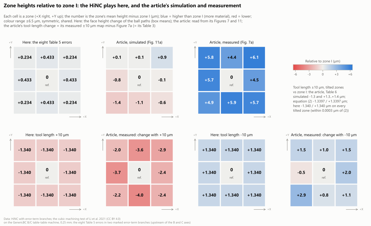
With the errors on and the controller unaware of them, the tool tip of each of the 74,661 TCP steps sat where the prediction put it, the largest gap 7.4×10⁻¹² mm, and the machine's X, Y and Z differed from the nominal run by the typed touch-off turned with the nominal B and C, within 6.4×10⁻¹² mm. On the cut face the tip moved up to 35.0 µm sideways, which slides each zone's balls within its plane, and at most 1.52 µm up or down. The face the ball paths sweep stands +0.4326 to +0.4329 µm higher in the four zones II and +0.2337 to +0.2340 µm in the four zones III, −0.0002 µm in zone I: +0.433 and +0.234 µm against zone I, within 0.004 µm of the prediction. δx_BY gives +1.000 µm of it, 2.0 µm × sin 30°; β_BY takes off its angle times the zone's distance from the pivot, 0.464 and 0.657 µm; δz_BY takes 0.087 µm, −0.647 µm × (1 − cos 30°). The faces also tilt, by ±0.68 µm from a box's centre to its far corners in zone I, ±0.98–0.99 in zones II and ±0.89 µm in zones III, mostly through γ_BY and α_CB, which leave the zone means alone.
With the controller's tool length 10 µm too long, TCP lifts the spindle by 10 µm at every step, and the real tip stops 10 µm short along the tool: zone I stands +10.0000 µm high, a zone tilted 30° only +8.6600 to +8.6603 µm, so the tilted zones stand 1.3397 to 1.3400 µm below zone I. 10 µm too short turns every sign. That is the article's Eq. 2, (1 − cos 30°)·eL = 1.3397 µm, within 0.00024 µm, more than three times the zone heights these machine errors make here.
With the marks cleared, the switch still on and the same touch-off typed, the controller knows the errors:
the machine's linear axes stand elsewhere, by up to (15.6, 25.2, 6.5) µm from the nominal run, and the tip
comes back to the program but for a constant 5.85 nm. The tilted faces still stand +0.0500 µm high, as the
tool's direction keeps the errors' rotation under G43.4. On the Diff, zone I and zone II +Y,
whose rows have the same step count in both runs, are all green; what is left elsewhere is the ridges of
rows whose step counts differ.
Against the article: here +0.234 to +0.433 µm, the four zones of a kind alike; the article's simulation −1.4 to +0.9 µm, every zone different. The difference lies in where the part sits against the B and C axes and the point the errors turn about, which the article does not give, so the two compare only qualitatively. With every Table 5 value reversed, as a literal reading of its Eq. 4 puts them, the zones would stand 0.45 and 0.26 µm below zone I; neither reading matches the article's pattern. Its measured +4.4 to +6.1 µm leave +4.3 to +7.0 µm over its own simulation, which the authors put down to the ball's edge profile; the model's ball is perfect. For the tool length, the article's simulation gives 1.3 to 1.4 µm and its measurement −4.0 to −2.0 and −0.5 to +2.9 µm, where the authors see other factors at work.
The study puts constant errors only into the machine: the article machine's position-dependent errors, backlash, servo and heat are not here. The part's place, the pivot and the sign convention were chosen, and five of the errors have no lever in this placement. The ball is perfect and physics is off, with no cutting force, deflection or heat, and the article's zero-depth pass was left out. The face height change is computed from HiNC's per-step results; HiNC's own Diff reads the ridges between steps. Everything is simulated; no part was cut.
What it brought
- For a machining engineer: on a B/C table-table five-axis machine, the eight rotary-axis
errors a ball bar measured raise zones II and III of the cubic machining test by only 0.43 and 0.23 µm
against zone I, with the part centred on C and its face at the height where the axes cross; δx_BY, the
B axis 2 µm off along X, gives 1.0 µm of it alone, and with the part placed elsewhere the five errors
without a lever here would show. The zone means miss the faces' tilt, up to 1.97 µm across a box. A
controller tool length 10 µm off moves a 30° zone by exactly 1.34 µm, more than three times these zone
heights. A calibrated controller puts the tip back under
G43.4but not the tool's direction, and here leaves the tilted zones 0.05 µm high. Most of the 4.4–6.1 µm the article measured is not the machine's geometric error: the simulation accounts for about 1 µm, and the authors put the rest down to the edge profile. In HiNC, a machine's ball-bar results can go into its model, to see their shape and size on your own part before it is cut, with and without a controller that knows them. - For a teacher or a student: how an error becomes a tip offset through the kinematic chain, d = W⁻¹W₀(P + g) − P; why a touch-off cancels the errors only at B = C = 0; why an angular error's effect depends on its pivot, β_BY in zone II being 14 mm × 0.0019° = 0.46 µm; how a ball-end mill's face height takes both the tip offset and the turn of the tool axis, d_z + r(a′z − az); and why a simulation of one step per spindle revolution leaves ridges of f²/8R, 4.63 µm at 1/3 mm, which a vertex mean then reads.
- For someone deciding whether to use an agent with HiNC: a base built new from the article's numbers, the error-term project saved from it, and ten plays of about 90 s each at no more than 1.506 GiB. The predictions were written before the first play and met to 7.4×10⁻¹² mm on every TCP step's tip, to 0.004 µm on the ball paths' face height and to 0.00024 µm on the tool-length effect. Where the plan missed, the record says so as measured: six of twelve criteria failed as written, on how HiNC makes its steps, on formulas written for the TCP section only, and on a prediction for the unmarked run that missed; and this case does not explain the 4.4–6.1 µm the article measured.
Read the full case record: the cubic machining test with the eight rotary-axis errors
How the base project was built from the article, every value marked read, derived or chosen, is told in that record; it is the case's first public page.