BCAM thin blade, C axis 0.02 mm off: the same error makes the G1 blade thinner and the NX blade thicker (5-axis)
- Original source
- K. Rajain, G. Gómez Escudero, M. Bizzarri, H. Gonzalez Barrio, A. Calleja-Ochoa, L. N. López de Lacalle, M. Barton (Basque Center for Applied Mathematics; University of the Basque Country), High-quality smooth finishing of blade-like geometries via G1 multi-pass 5-axis flank CNC machining using conical cutting tools, Zenodo, 2025 — zenodo.org/records/15830311; described in The International Journal of Advanced Manufacturing Technology 136, 4383–4397 (2025), DOI 10.1007/s00170-024-14898-6
- Search keywords
zenodo 15830311,G1 multi-pass 5-axis flank CNC machining conical- Licence
- The data set: Creative Commons Attribution 4.0 International, provided as is and as available, without warranty. The published article is not open access. The few facts this page takes from it come from the base case: the block and its steel, and that the paper names no machine and does not say how its measurements were aligned. The base case read them in the authors' submitted version in the BCAM repository (CC BY-NC-SA 3.0 ES) and did not keep that file. This page reproduces no picture from the paper or the data set. Every picture is a HiNC capture.
- Attribution
-
NC programs, blade models and deviation map: K. Rajain, G. Gómez Escudero, M. Bizzarri, H. Gonzalez
Barrio, A. Calleja-Ochoa, L. N. López de Lacalle, M. Barton, "High-quality smooth finishing of
blade-like geometries via G1 multi-pass 5-axis flank CNC machining using conical cutting tools",
Zenodo (2025), https://zenodo.org/records/15830311; described in K. Rajain et al., The International
Journal of Advanced Manufacturing Technology 136, 4383-4397 (2025),
https://doi.org/10.1007/s00170-024-14898-6. Licensed CC BY 4.0
(https://creativecommons.org/licenses/by/4.0/), provided as-is and as-available without warranties
(CC BY 4.0 Section 5). Changes: the three G1 programs are played from copies with two lines changed
(TOOL CALL 0 -> TOOL CALL 22; CYCL DEF 7.0 -> CYCL DEF 7.0 DATUM SHIFT); blade_full.obj was placed
in the programs' frame and meshed into a closed solid; the map's labelled points were located on the
image; for pictures only, 03 and the G1 copy of 04.3 were cut short so that a play ends in the middle
of the bottom pass.
This case changes no program beyond that. The close-up pictures come from that shortened G1 copy of 04.3. Tech Coordinate's agent added one error term to the simulated machine and chose where it sits, its size and sign, and the touch-off presets. The authors do not endorse Tech Coordinate, HiNC or this case. - About the case
- This case builds on the accepted BCAM thin blade and keeps everything from it: the blade in a 60 × 50 × 60 mm block of AISI 1045 steel, the generic five-axis machine with a B/C table, and the tapered ball-end cutter 47 mm out of its shrink-fit holder. It also keeps the two flank finishes: NX's 03 and the authors' G1 programs 04.1–04.3. Both run under Heidenhain M128 (TCPM: while the rotary axes turn, the controller keeps the tool tip on the programmed path). What this case adds is a constant geometric error, built into the machine as an error term: the C axis turns about a centre 0.020 mm off in +X. The agent chose the size, a typical value for a five-axis machine whose kinematics were never calibrated, and the sign. The paper names no machine and measured no machine error.
The story
In the base case, the machine was built exactly to design. The whole chain played through, and the finished parts matched the paper's 45 measuring points to 0.0019 mm on average for NX and 0.0047 mm for G1. The two finishes cut the same face from opposite B/C solutions: NX with B −6.56…−5.00° and C 45–125°, G1 with B +5.24…+6.58° and C 244–299°.
Here an AI agent was asked to show what one constant geometric error of the machine does to an accepted case. It picked an error common on five-axis machines: the C axis turns about a centre 0.020 mm off in +X from where the controller thinks it is. ISO 230-7 calls this EX0C. The error sits on a branch of its own directly upstream of the C axis, as a static translation marked as an error term. The simulated controller works out the machine coordinates without that branch, like a real controller that does not know its machine's error. The simulated machine still moves and cuts with it.
On a real machine, a touch-off at B = C = 0 would absorb the shift the error causes there into the work offsets. So every run with the error on used the two Heidenhain presets that such a touch-off finds.
Before the first play, the agent wrote down its prediction and seven pass criteria. Then it played each finish four times at 0.0625 mm, the case's acceptance grid. Each play started from the case's stand-in for the semi-finished stock: the design face grown outward by 0.484 mm. The four plays were:
- error terms off: the nominal run, whose cut is the ideal shape for every comparison;
- off again, with a Diff: the noise floor;
- on, with the error marked: the controller does not know about it;
- on, with the mark cleared: the controller knows about it, as after a kinematics calibration such as Heidenhain's KinematicsOpt.

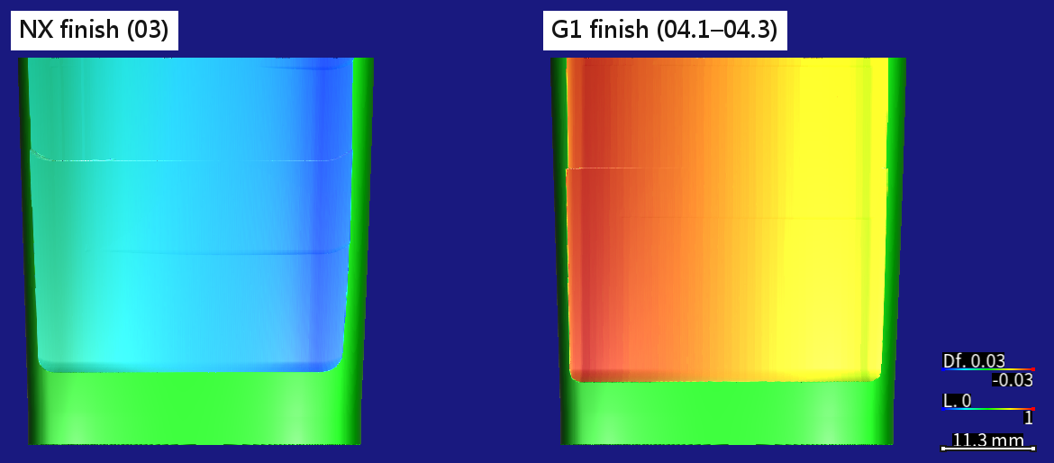
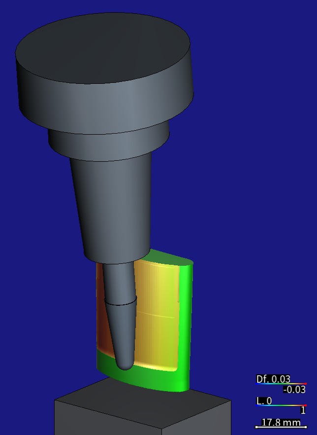
Pictures rendered by HiNC at 0.0625 mm from the NC programs and blade model of K. Rajain et al., Zenodo 15830311, CC BY 4.0, on the case's generic machine with the error the agent built in. Diff colours: red = cut too deep, blue = material left, green = same as the nominal cut. The scale runs from −0.03 to +0.03 mm, so both signs get equal weight.
| Key number | What it is |
|---|---|
| 0.020 mm | how far the C axis's centre of rotation sits off in +X (EX0C): a typical size the agent chose, since the paper measured no machine error |
| 2.6×10⁻¹³ mm | largest gap between the formula (d(1 − cos C), −d·sin C, 0) and the tip offset at NX's 1,757 cutting steps, where d = 0.020 mm and C is the step's C angle; at G1's 1,487 steps the gap is 1.4×10⁻¹³ mm |
| +0.0101 / +0.0184 / +0.0266 mm | the NX face against its own nominal cut, p01 / median / p99: material left, so the blade is thicker |
| −0.0291 / −0.0215 / −0.0114 mm | the G1 face, measured the same way: cut too deep, so the blade is thinner |
| 0.0010 / 0.0004 mm | NX / G1: largest gap between the five medians along the chord and the prediction written before the first play |
| 9 → 20 | the paper's G1 points outside ±0.01 mm, out of 25: base case → with this error (derived from the measured shift, not from a play) |
| 5×10⁻¹⁰ mm | largest gap, vertex by vertex, between the nominal part and the part cut by a controller that knows the error |
| 31 min | the eight full plays one after another on the shared 32-thread server, restarts included; each play took 55–286 s and at most 5.64 GiB of memory |
Four of its eleven dilemmas
Touching off on a machine with the error
A single translation in front of the C axis shifts the table by the error even at C = 0. A real touch-off at B = C = 0 absorbs that shift into the work offset. HiNC's own program-zero measurement works on the nominal chain, so it does not. This case also has two presets. NX runs from preset 1, the block's top corner. G1 starts from preset 2, the C table's centre, and a datum shift brings it back to the same program zero. So the runs with the error on typed in the presets such a touch-off finds: (−29.98, −25, 46.6) and (0.02, 0, −100). Had either been missed, every step of that program would carry a constant offset. None does.
The real size, not ten times larger
The design proposed showing a tenfold error, 0.2 mm, in the pictures. At that size the cutter would miss the stand-in stock on about 2 % of the finished face, all along the lower edge of the NX bottom pass; the deviation would be clipped there, and every picture and number would need converting back. At the real 0.020 mm, though, the deviations are only 16–46 % of a 0.0625 mm cell and could have drowned in noise. The plan ran the real size only, and the grid reads it. The run where the controller knows the error lands within 5×10⁻¹⁰ mm of the nominal cut. The control's Diff stays within ±0.001 mm. At 99 % of the points, the measured face agrees with an independent sweep of the cutter to 0.0004 mm.
Steps off the formula, all in the air
Checked over every step, not only the cutting ones, 137 NX steps and 168 G1 steps were off the formula, by up to 0.0355 mm. Grouped by program line, they are the tool calls, the B/C turn before M128, the first rapid approach after it, and the B/C return after M129. In 03 and 04.1 the tool-change position is a fixed machine position that no typed preset moves, so there the tip is off by the error itself: 0.020 mm, turned with C (−0.020 mm in X at C = 0). The other steps are transitions. The first rapid after M128 and the return after M129 are interpolated in machine coordinates between such positions and the formula, and in 04.2 and 04.3 the tool call and the B/C turn wait where the previous program ended. None of them touches the part, and each play's own machine coordinates, run through the kinematics, reproduce every one of them to 1.7×10⁻¹³ mm. By the same reasoning, on a real machine with this error the approach would be off by the same amount, in the air.
The paper's points can only be derived
The paper measured its 45 points on blades finished from real semi-finished stock. To save the roughing and semi-finishing (197,265 steps, 1 h 54 min), every run here starts from the stand-in stock, with physics off. So the agent measured the shift the error causes at each point on the stand-in and added it to the base case's accepted reading. Adding is sound for two reasons. The finish removes all the stock at those points, and the base case's own stand-in trial and its full acceptance agreed there to 0.0014 mm. Wherever the page uses the result, it calls it derived: 20 of the 25 G1 points end up outside ±0.01 mm instead of 9.
The other seven are in the full record. Among them: a check the plan asked for on steps at C = 0, when no step under M128 has C = 0; the question of which run the machine coordinates should be compared with; and whether "NX at least 99 % positive" should count a strip of stand-in stock that the finishing cutter never reached.
The result
All twelve plays finished, eight at 0.0625 mm and four trimmed ones at 0.25 mm. There was no collision and no rapid move through material. NX took 2,410 steps a play and G1 2,011, as in the base case.
With the controller unaware of the error, the tip at every cutting step sits on the predicted offset, within 2.6×10⁻¹³ mm. The offset depends on the C angle alone. At C 45–125°, the NX cutter moves to the air side of the face; at C 244–299°, the G1 cutter moves into the material. So the NX face is left thick all over: 98 % of it by +0.0101 to +0.0266 mm, more toward +X. The G1 face is cut too deep all over: 98 % of it by −0.0291 to −0.0114 mm, deepest toward −X. Along the chord, the medians stay within 0.0010 mm of the prediction, and they do not change with height.
Derived by adding the shift to the base case's readings, 20 of the paper's 25 G1 points would fall outside ±0.01 mm, against 9 without the error; the paper measured all 25 inside. None of this tells whether the authors' machine has such an error: the paper does not say how its measurements were aligned, and an alignment can take up part of an offset.
With the mark cleared, the controller puts the tip back on the program and cuts the nominal part to 5×10⁻¹⁰ mm. To do so it moves X by about +0.020 mm and Z by about 0.002 mm more than the nominal run at every cutting step, and leaves B and C unchanged. The control run repeats the nominal run step for step, and its Diff stays within ±0.001 mm.
The agent chose the error's size and sign. With the error in −X, the signs would swap: NX thinner, G1 thicker. Everything here is simulated; no blade was cut.
What it brought
- For a machining engineer: under M128, a C axis 0.020 mm off moves this blade's whole face by 0.010–0.029 mm: thicker with the NX program, thinner with G1. A touch-off removes the offset only at C = 0, and the flank is cut with C 45° or more away from there. Two programs on opposite B/C solutions are pushed in opposite directions. So when two programs disagree on one machine, check whether its kinematics are calibrated before blaming a program. A wrong tool radius moves both faces the same way; a misplaced C axis moves them apart. A controller with calibrated kinematics removes the error completely, at the cost of 0.020 mm more travel on the linear axes. In HiNC you can build in a constant error measured on a machine and see its effect on your own part before it goes on the machine.
- For a teacher or a student: how a rotary axis's location error becomes the tip offset (d(1 − cos C), −d·sin C, 0), and why that depends on C alone, not on B or on where the tool is. Why a tool tilted only 5–6.6° still does not mean an error as small as on a three-axis machine: C turns away from the touch-off pose by 45–125° for NX, or 61–116° for G1 (the short way). That prints its error at 0.77–1.77 or 1.02–1.70 times its size, while a B error would print at about a tenth. Why the face keeps only the part of the offset along its normal. And how a real touch-off differs from HiNC's program-zero measurement on the nominal chain.
- For someone deciding whether to use an agent with HiNC: from an accepted case to the error, its prediction and twelve plays. The eight full plays took 31 minutes on a shared server, at most 5.64 GiB each; four trimmed plays and one play for the close-ups came on top. The prediction was committed before the first play. It held step by step within 2.6×10⁻¹³ mm and along the chord within 0.0010 mm. Three parts of the plan could not be checked as written: there is no step at C = 0 under M128, the plan did not say which run to compare machine coordinates with, and the NX box includes a strip of stand-in the cutter never reached. The record says so instead of bending them.
Read the full case record: BCAM thin blade, C axis 0.02 mm off
The accepted case this page builds on, with how the blade was placed, the tools worked out and the machine chosen: BCAM thin blade.