A roundness test part with the three squareness errors measured on its machine: only the X–Y squareness makes the circles oval (3-axis)
- Original source
- M. Holub, R. Jankovych, J. Vetiska, J. Sramek, P. Blecha, J. Smolik, P. Heinrich, Experimental Study of the Volumetric Error Effect on the Resulting Working Accuracy—Roundness, Applied Sciences 10(18), 6233 (2020), MDPI — DOI 10.3390/app10186233. The paper publishes no model, program or data set. The case uses its printed numbers: the part of Fig. 3a, the travels of Table 1, the cutting data of Table 2, the ballbar squareness of Tables 8–10, the LaserTRACER calibration in Fig. 6 and the roundness of Tables 11–13.
- Search keywords
app10186233,Experimental Study of the Volumetric Error Effect on the Resulting Working Accuracy Roundness- Licence
- The paper is under Creative Commons Attribution 4.0 International (CC BY 4.0) and comes without warranty. The case takes the paper's numbers only: most are printed, while the two Z squareness values and the values of Fig. 19 are read off charts. This page reproduces no picture from the paper. Every picture is a HiNC capture or a chart drawn from HiNC's results and the paper's table numbers.
- Attribution
-
Measured data and part dimensions: M. Holub, R. Jankovych, J. Vetiska, J. Sramek, P. Blecha,
J. Smolik, P. Heinrich, "Experimental Study of the Volumetric Error Effect on the Resulting Working
Accuracy—Roundness", Applied Sciences 10(18), 6233 (2020), https://doi.org/10.3390/app10186233.
© 2020 by the authors, licensee MDPI, Basel, Switzerland. Licensed CC BY 4.0
(https://creativecommons.org/licenses/by/4.0/), provided as-is without warranties (CC BY 4.0
Section 5). Changes: the stock and design models, the NC programs and the HiNC project are Tech
Coordinate's, built from the article's numbers; two values were read from a bar chart and rounded to
whole µrad; no figure reproduced.
Tech Coordinate's agent added two error-term branches to the simulated machine and chose where they sit and their pivots; the signs follow the ISO 230-1 convention the paper states, the ballbar value taking the sign of Fig. 6. The authors do not endorse Tech Coordinate, HiNC or this case. - About the case
- Holub et al. calibrated a three-axis vertical machining centre (a KOVOSVIT MAS MCV 754 QUICK with a Sinumerik 840D sl) with a LaserTRACER, switched on its volumetric compensation, checked the machine with a ballbar before and after, and cut the same test part before and after: a Ø300 flange, a Ø200 boss on it and a Ø100 bore. The volumetric error fell from 49 to 14 µm; the roundness of the part fell far less, and the bore's got slightly worse. The paper publishes only numbers, so unlike the other error-term cases this one has no accepted case to build on: the agent built and accepted its own base project from the printed numbers first, then put in the errors. The simulated machine is a shapeless three-axis machine with the paper's travels, not the one they measured; it borrows its three squareness errors.
The story
The paper concludes that the circularity error is "significantly affected by the squareness error of two relative axes in the machining plane". An AI agent asked for error-term showcases, paper cases welcome, took the paper's own part to see that statement in simulation. Through HiNC's web API it built a base project: the part revolved from Fig. 3a, a stock with 0.5 mm left on the three cylinders, a Ø16 four-flute end mill in an ER25 collet chuck as Table 2 names it, and one climb-milled finishing circle for each diameter at Table 2's cutting data. A 1 mm play accepted it: every line of the three programs ran, cutting only on the three circles and their lead-ins, with no collision.
Then the agent put the errors in, each on a branch of its own marked as an error term, directly upstream of one axis. The ballbar's X–Y squareness, 22.4 µm/m, went in front of Y. The LaserTRACER's squareness of Z to Y and to X, +33 and −56 µrad read off the paper's bar chart, went in front of Z as one 65 µrad rotation. The controller solves its axes as if the marked branches were not there. The simulated machine still moves and cuts with them whenever the project's Enable Error Terms switch is on, like a real machine whose controller does not compensate them. Both pivots sit where the tool is when the operator touches off at program zero, so the G54 a real touch-off would find, (325, 250, −425), stays as it is.
Before the first play, the agent committed a plan with the tool-tip offset it expected, the deviation of the part at every height and angle, and fourteen pass criteria; three read-only reviewers had checked the draft first. It played the three programs at 1 mm, probed the boss alone at 0.25 mm, and played the whole part at 0.25 mm, geometry only:
- error terms off: the nominal cut, which every comparison is measured against;
- off again, with HiNC's geometry difference (Diff) against the nominal cut: the noise floor;
- on, with the errors marked, so the controller does not know them.
A fourth run at 1 mm cleared the marks, as a controller with calibrated kinematics would know the errors.
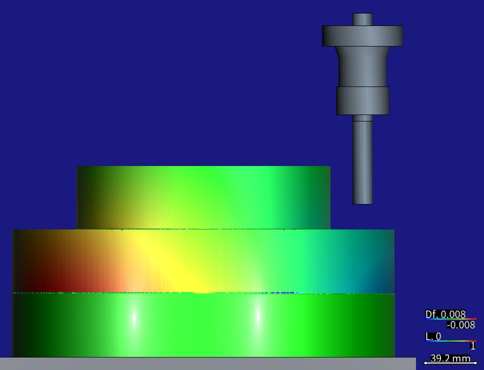
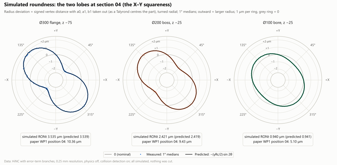

HiNC rendered these pictures on the agent's simulated machine with the two error-term branches it built in; the part's dimensions, the cutting data and the error values come from Holub et al.'s CC BY 4.0 paper. The cut parts were put back on the canvas with their Diff, not replayed; for the first picture, a parking program brought the tool into view without cutting. The colours are HiNC's geometry difference (Df in the colour bar) against the part the nominal run cut, on a symmetric scale: red = cut too deep, blue = material left, green = 0. The grid is 0.25 mm. The polar chart is drawn from the cut part's mesh and labelled with the paper's values.
| Key number | What it is |
|---|---|
| 22.4 µm/m · 65 µrad | the errors, on two branches: the X–Y squareness the paper's ballbar measured on the Ø300 circle before compensation (Table 8), and the squareness of Z to Y and to X, +33 and −56 µrad read off the LaserTRACER bar chart (Fig. 6, to ±1–2 µrad), combined into one 65 µrad rotation that moves the tool toward 30.5° (+X+Y) as it goes down |
| 1.24×10⁻¹³ mm | the largest gap, over all 5,411 paired steps, between the measured tool-tip offset and the formula δ = A·(X, Y, Z) written before the first play. The machine coordinates are bit for bit those of the nominal run |
| 3.535 · 2.421 · 0.940 µm | the simulated out-of-roundness (RONt) of Ø300, Ø200 and the bore, mean of seven sections 5 mm apart; predicted γ × tool-centre radius, 3.539 · 2.419 · 0.941 µm. The seven sections of each diameter agree within 0.0024 µm |
| 65 µrad · 3.25 µm | the lean of the axis the three cylinders share, read from 21 section centres (65.10, 64.94 and 65.02 µrad per diameter); over a 50 mm wall it comes to 3.25 µm against the end face. The cylinders stay coaxial, and the lean does not change the roundness |
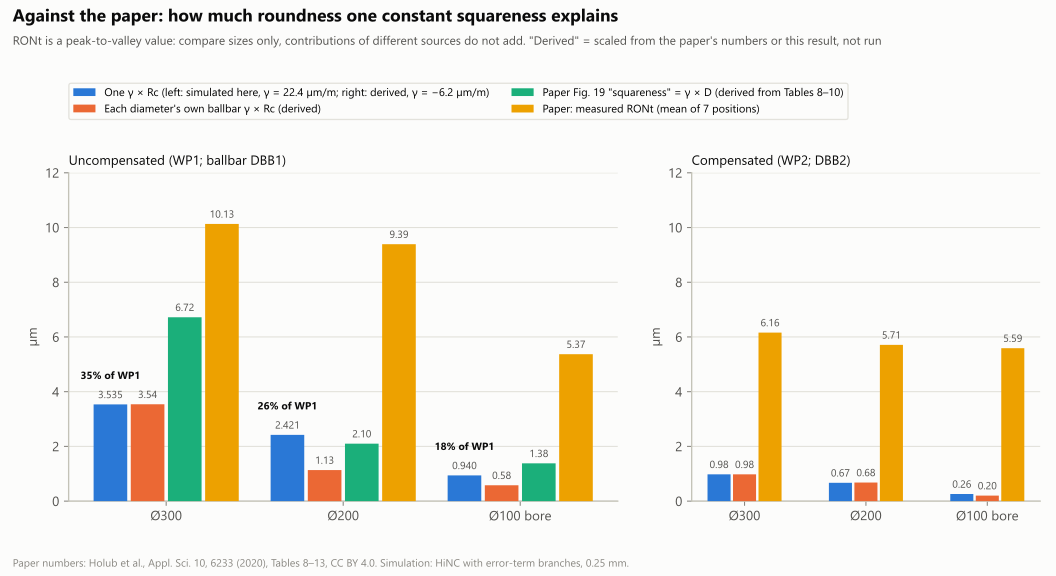
| 35 % · 26 % · 18 % | how much of the roundness the paper measured on the uncompensated part (10.13, 9.39 and 5.37 µm, mean of seven positions) this one constant squareness explains |
| 0.98 · 0.67 · 0.26 µm | what the residual squareness after compensation (−6.2 µm/m) would leave, scaled; the compensated part still measured 6.16, 5.71 and 5.59 µm, so what the compensation left is mostly not squareness |
| 24 of 24 | feature boxes at section 04 within the tolerance fixed before the play, their medians within 0.029 µm of the prediction |
| 240.3 s | server time for all ten plays. On a shared 32-thread server, each whole-part play at 0.25 mm took 40–55 s and at most 6.51 GiB of memory |
Four of its eleven dilemmas
P0 is not a touch-off
A real machine touches off on the part, and the G54 it finds absorbs whatever the errors shift at that pose. While the errors were marked, P0 read (325, 250, −425) exactly: it measures on the machine the controller knows, which leaves the marked branches out, and with both pivots where the tool is at the touch-off pose a real touch-off finds the same value. With the marks cleared, as for a controller that knows the errors, P0 read it 5.6 µm off in X and 26.45 µm off in Z. P0 takes program zero at machine zero and does not solve the chain at the touch-off pose: 250 mm × 22.4 µrad gives the X part, 406.9 mm × 65 µrad the Z part. A real touch-off would still find (325, 250, −425), so that run typed the value in, as HiNC's manual advises, and its machine coordinates came out bit for bit those of the marked run.
Half a micrometre on a 0.25 mm grid
The bore's two lobes are 0.47 µm, 0.19 % of a grid cell, and one step per spindle revolution leaves scallops 2.3–3.0 µm high on every wall, taller than the lobes. The agent did not scale the errors up, which would have taken the numbers away from the paper's. It wrote a ×10 fallback with a numeric trigger into the plan and probed the boss at 0.25 mm first. The nominal and the on runs step at the same machine coordinates, so the scallops cancel in the difference, and a fit of harmonics up to the second reads the lobes through what is left. The residual is at most 0.122 µm on the bore, and the fallback never fired.
A lean that rests on an assumption
An error upstream of Z tilts the Z travel and, with it, the head and the tool axis. The travel's tilt alone would shift each circle sideways by its depth × 65 µrad; the walls lean because the tool axis tilts too. The paper never measured its spindle's tilt, so the 3.25 µm lean of a 50 mm wall is a consequence of the model, not a fact of that machine. All 21 section centres lie on one line through program zero, so the cylinders stay coaxial; the 3.25 µm between the Ø300 and Ø200 centres is that one axis over 50 mm of height. Had the spindle not tilted, the walls would stand upright and Ø300 and Ø200 would sit 3.3 µm apart: a coaxiality check on a real part tells the two cases apart.
Outliers that are not the error
Over 2.1 million vertices, 98 % of the distances lie between −7.30 and +5.04 µm, yet the extremes reach −64.6 and +1,000 µm. Every vertex beyond 0.02 mm, 3,120 of them, was checked by brute force. 52 came from the distance search, which looks at the 12 nearest triangle centres and misses the large triangles of the uncut stock beside them: their true distance is 0. The other 3,068 are real, on the three 0.5 mm steps the programs leave at the feet of the walls: a step two cells wide flips in the 0.25 mm mesh when the tool moves a few micrometres. None lies in a judged region; on the Diff pictures they are the specks along the step edges.
The full record has the other seven, among them the three reviewers who corrected the plan before it was committed, an extra step at a tool change that made the runs pair by program line, and a control run that passed 5 % inside its threshold.
The result
All ten plays ran to the end with no collision. The whole part takes 5,411 steps, 5,412 with the error terms on: one more at a tool change.
With the errors on and the controller unaware of them, the tool tip of every paired step sat where the formula written before the first play put it, within 1.24×10⁻¹³ mm. Moving along X, the tip drifts toward −Y by 22.4 µm/m; going down, it moves toward +X by 56 µm/m and toward +Y by 33 µm/m. Every step's machine coordinates are bit for bit those of the nominal run.
On the part, the X–Y squareness cuts every circle into an ellipse with its long axis at 135°/315°. Its out-of-roundness is γ times the radius of the tool-centre path, because the ellipse is that path and the wall its envelope: 3.535, 2.421 and 0.940 µm on Ø300, Ø200 and the bore, against 3.539, 2.419 and 0.941 µm predicted, the same at all seven heights. The Z squareness leaves each section round and moves its centre with depth: all 21 section centres lie on one line through program zero, tilted by 65 µrad, the deeper sections displaced toward 30.5°. The three cylinders stay coaxial, and each wall leans 3.25 µm over 50 mm against the end face. The deepest deviation on the walls, in 1° medians, is −8.18 µm at the bottom of the flange band, at 222.5° (−8.11 µm at 218.5° predicted; the curve is flat there). The 24 feature boxes fixed before the play all held their predicted means, the largest gap 0.132 µm.
Against the paper: measured before compensation, the paper's part was out of round by 10.13, 9.39 and 5.37 µm. The constant X–Y squareness explains 35 %, 26 % and 18 % of that. The γ × D the paper plots is about twice what one squareness makes. After compensation, the residual squareness would leave 0.98, 0.67 and 0.26 µm, while the paper still measured 6.16, 5.71 and 5.59 µm: what the compensation left is mostly not squareness. The paper names the deflection under the cutting force and, for the bore, another machining technology; neither is in a geometric model, and neither is heat.
With the marks cleared, as a controller with calibrated kinematics would know the errors, the 1 mm run moved the machine exactly as the marked run did. In a plain three-axis program the controller computes the machine coordinates from the program and its offsets alone, so the errors are cut in either way. On the real machine it was the controller's compensation table that made the second part rounder; HiNC does not simulate it.
The study models three constant squareness errors only, on two error-term branches: no positioning, straightness or scale error, no thermal growth. The Z values were read from a bar chart, to ±1–2 µrad, and the ballbar's squareness has no stated sign; the signs set the direction of the ellipse and of the lean, not their size. The lean of the walls rests on the spindle tilting with Z. The finishing programs are the agent's, and the plays are geometry only, with no cutting force or deflection. Everything is simulated; no part was cut.
What it brought
- For a machining engineer: the three squareness errors of one three-axis machine act very differently on a circle-milled part. The squareness of the machining plane's two axes cuts every circle into an ellipse, out of round by γ × the tool-centre radius: 3.5 µm on Ø300 for this machine's 22.4 µm/m. The two Z squareness errors, the largest constant terms the LaserTRACER found, leave the roundness alone and lean the axis the cylinders share: 3.25 µm over a 50 mm wall against the end face. To make such a part rounder, compensate the machining plane's squareness. Whoever measures only roundness will not see the Z squareness; the squareness or position of the axis against the end face will. In HiNC, a constant error measured on a machine can go into its model, to see its shape and size on your own part before anything is cut.
- For a teacher or a student: how a squareness travels through the machine's chain into the tool-tip offset δ = A·(X, Y, Z); why the out-of-roundness is set by the radius of the tool-centre path, which is also why the paper's γ × D is about twice the out-of-roundness; why a Talyrond centred on the part does not see a tilted axis; and how a real touch-off and HiNC's P0 differ.
- For someone deciding whether to use an agent with HiNC: a base project built from a paper's printed numbers alone, an error-term copy of it, and ten plays totalling 240.3 s of server time, at most 6.51 GiB each. The predictions were written before the first play and met to 1.24×10⁻¹³ mm on the tool tip, 0.0022 µm on the lobe term and 0.16 % on the axis tilt. The record also writes down the method's own limits: artefacts of the distance search, steps flipping in the mesh, lines of vertices reading off, and a control run 5 % inside its threshold.
Read the full case record: the roundness test part with its machine's squareness errors
The same paper's three squareness errors on another part, the ISO 10791-7-style test piece of the RPTU benchmark: RPTU part 8, three squareness errors of 24–56 µrad.