Mars rover wheel: with the A axis tilted 0.005°, the 0.75 mm skin runs from 0.733 mm at the faceplate end to 0.767 mm at the tailstock end, and a calibrated controller changes nothing (4-axis)
- Original sources
- Numbers only, no model: A. Rankin et al. (Jet Propulsion Laboratory), Assessing Mars Curiosity Rover Wheel Damage, IEEE Aerospace Conference 2022 (PDF on JPL's site); E. Lakdawalla, Curiosity wheel damage: The problem and solutions, The Planetary Society, 2014 (planetary.org); photographs of the real wheels on NASA's page Curiosity's and Perseverance's Wheels.
- Search keywords
Curiosity's and Perseverance's Wheels,Rankin 2022 Mars rover wheel wear,Curiosity wheel damage Planetary Society- Licence
- Only facts (dimensions and counts) are taken from the sources; the IEEE paper is © 2022 IEEE, and only its numbers are used. The wheel shown here is a model Tech Coordinate's agent built from those numbers; NASA's illustration is not reproduced, since NASA imagery is not in the public domain and may be used only editorially outside promotion. Every picture here is a HiNC capture, a chart drawn from HiNC's results or a schematic the agent drew. The machine, the programs and the error are the agent's own, and the error's size and sign are not a measurement of any machine.
- Attribution
-
As the base case's source record gives it:
Wheel numbers and reference image: NASA/JPL-Caltech. Rebuilt for machining simulation by Tech
Coordinate's agent; not a NASA or JPL design file and not endorsed by NASA.
The reference image, NASA's comparison illustration, served only inside the case, to estimate the chevron shape; it is not shown here. Tech Coordinate's agent added one error-term branch to the simulated machine and chose its kind, its size, its sign and its pivot; EB0A is the ISO 230-7 name for this kind of error, and its value is not a measurement of any machine. - About the case
- The accepted programs of the Mars rover wheel: one grouser pitch of Curiosity's wheel, rebuilt from published numbers and a photograph, clamped across its full 400 mm width between the faceplate of a generic four-axis machine's A table and a tailstock centre, and milled down to its 0.75 mm skin by two Fanuc four-axis programs. Here that machine gets one constant geometric error: its A axis is tilted 0.005° about Y against the X travel (EB0A in ISO 230-7), so the tailstock end of the line through the two centres sits 46 µm low over 531 mm. That is a typical size the agent chose; nobody measured this generic machine.
The story
In the base case an AI agent rebuilt Curiosity's wheel from published numbers and a photograph, clamped one grouser pitch, the full 400 mm wide, between the faceplate and the tailstock centre of a generic four-axis machine, and wrote two positional Fanuc programs with G43 H tool lengths: T1, a Ø12 end mill, roughs the chevron groove, and T2, a Ø10 end mill, finishes its floor and walls down to the 0.75 mm skin. The case was accepted at a 0.125 mm grid. The programs have no RTCP: the tool axis always points at the wheel's centre, the A axis turns the wheel, and X runs along its width.
Here the agent gave that machine one common geometric error. Its A axis, the line through the faceplate centre and the tailstock centre, is tilted 0.005° about Y against the X travel: EB0A in ISO 230-7, the A axis's orientation error about Y. On the shop floor that reads as the tailstock end sitting 46 µm lower than the faceplate end over the 531 mm between centres. The error sits on a branch of the machine marked as an error term, directly upstream of the A axis, with its pivot on the floor at mid-width at A 0, where the case assumes a shop touches off. The controller solves its axes as if the branch were not there, while the simulated machine moves and cuts with it whenever the project's Enable Error Terms switch is on. The agent changed no line of the programs and kept the case's own G54: the touch-off it assumes would find a value within 2.25 µm of it.
Before the first play, the agent committed a plan with the tool-tip offset it expected, the deviation of every feature and seven pass criteria. A trimmed case, the outboard 150 mm with the first chevron bend and the part above the stiffening ring, played first at 0.25 mm, to check the build and the step formula. Then the whole groove played at 0.125 mm, geometry only, three times:
- error terms off: the nominal cut, which every comparison is measured against;
- off again, with HiNC's geometry difference (Diff) against the nominal cut: the noise floor;
- on, with the error marked, so the controller does not know it.
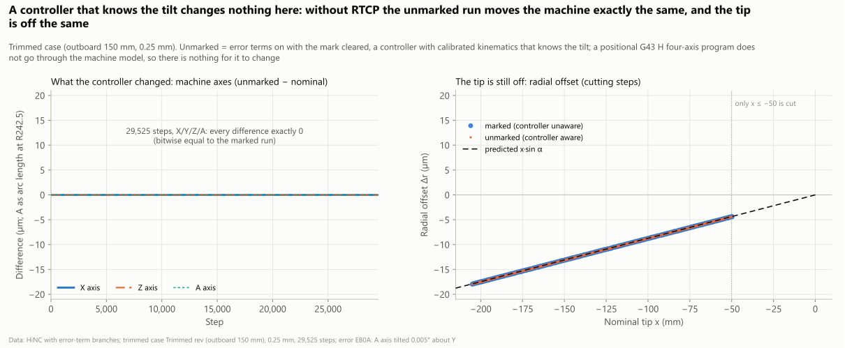
The trimmed case played these three and a fourth with the mark cleared, as a controller with calibrated kinematics would know the tilt. The programs are positional four-axis work: the controller turns them into machine coordinates from the program words, the work offset and the tool length alone, and never reads the machine's chain. So the plan said that run must match the marked run bit for bit.
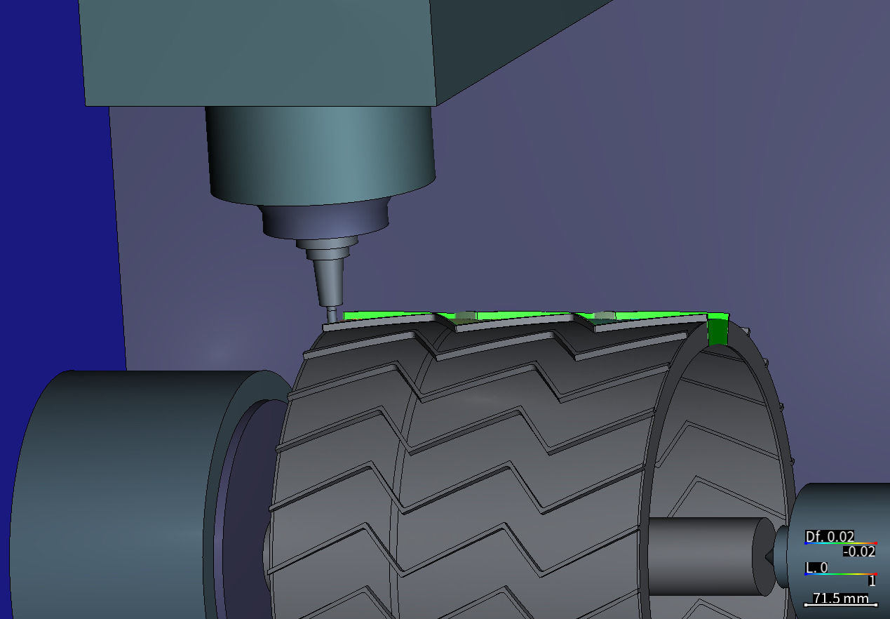
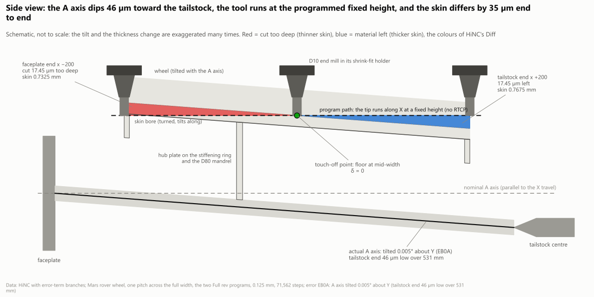
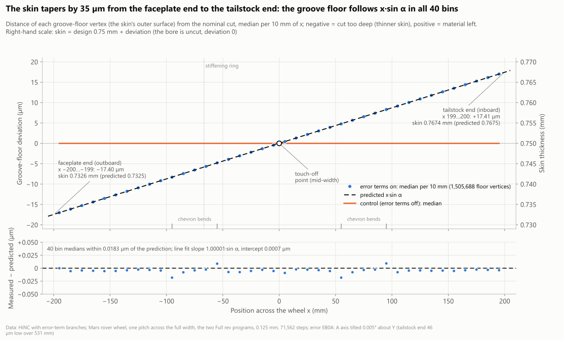
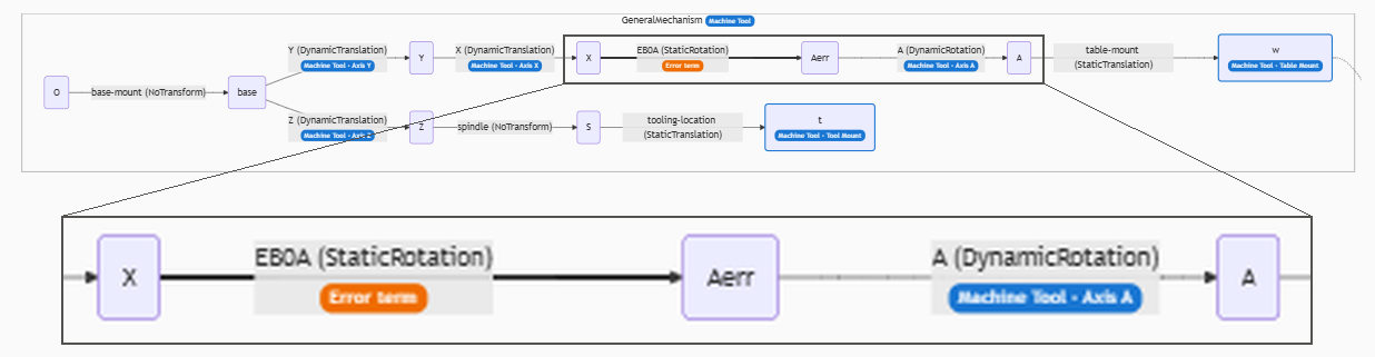
HiNC rendered these pictures from the wheel model Tech Coordinate's agent built from published numbers and a photograph, on the agent's simulated machine with the error-term branch it built in; none is a NASA or JPL design file. The cut parts were put back on the canvas with their Diff, not replayed; for the first picture, a parking program brought the tool into view. The colours are HiNC's geometry difference (Df in the colour bar) against the part the nominal run cut, on a symmetric scale of ±0.02 mm: red = cut too deep, blue = material left, green = 0. The grid is 0.125 mm. The charts are drawn from HiNC's step results and the exported cuts; the side view is a schematic.
| Key number | What it is |
|---|---|
| 0.005° · 46 µm | the error: the A axis, the line through the faceplate and tailstock centres, tilted 0.005° about Y against the X travel (EB0A in ISO 230-7), so the tailstock end sits 46 µm low over the 531 mm between centres. A typical value the agent chose, not a measurement; every deviation here is proportional to it |
| 4.07×10⁻¹³ mm | how far, at most, the measured tool-tip offset of any of the 71,562 steps lies from the formula written before the first play. The machine coordinates X, Y, Z and A are bit for bit those of the nominal run |
| 17.98 µm | the largest tip offset on a cutting step, 17.98 µm predicted: T1 entering at x −206, the end of the cutting range. At the touch-off point the offset is 0 |
| 0.7326 → 0.7674 mm | the skin at the faceplate end (x −200…−199) and at the tailstock end (x 199…200), designed 0.75 mm: 34.8 µm end to end, against 0.7325 and 0.7675 mm predicted at x = ∓200 |
| 0.0183 µm | how far, at most, the medians of the floor's 40 bins of 10 mm, over 1,505,688 vertices, lie from x·sin α at each bin's centre; a straight line fitted through the floor has the slope 1.00001·sin α. Around the wheel nothing changes: 2.9×10⁻⁶ µm per degree |
| ±0.26 · ±0.49 µm | the walls in their top 0.5 mm: +0.265 and +0.494 µm on walls facing the faceplate (material left), −0.264 and −0.494 µm on walls facing the tailstock (cut too deep), on the long 24° and the short 51° segments; predicted +0.266, +0.496, −0.266 and −0.496 µm |
| bit for bit | the trimmed run with the mark cleared, as a calibrated controller would know the tilt, against the marked run: its 11 step series, HiNC's Diff statistics and the 3,139,116 vertices of its cut are identical. Without RTCP the controller has nothing to change |
| ±4.8×10⁻¹⁰ mm | the control run against the nominal cut, from the 1st to the 99th percentile over 4,316,019 vertices: the noise floor, more than seven orders of magnitude below the error's ±17 µm |
| about 40 min | server time for the seven plays, 2,427.7 s. On the shared 32-thread server, each whole-groove play at 0.125 mm took 9.6–12.6 min and at most 17.06 GB of memory |
Four of its nine dilemmas
An error the touch-off would swallow
The first proposal was a location error of the A axis, to make the skin vary around the wheel. But program zero sits on the A axis, and on such a job a shop finds G54's Y and Z on the A axis anyway, so a shift of the axis goes into the work offset and leaves nothing on the part. Even without a touch-off, the skin would only be thinner all round, the same at every angle. A skin that varies around the wheel needs a part clamped off-centre, which is runout of the fixture or the mandrel, not an error of the machine; HiNC gives a fixture no error terms, and a fixture is placed where it really sits. What a touch-off cannot absorb is the direction of the axis, so the agent put in EB0A. On the part, the deviation depends on x only: the term around the wheel is 2.9×10⁻⁶ µm per degree. That a location error vanishes into G54 is the design's derivation; no run played it.
A pivot where the touch-off is
A static rotation needs a pivot, and the pivot decides how far the whole part moves. At the faceplate centre, where the axis stays put while the tailstock end sinks, the same tilt would bring a constant shift of (+21.2, 0, −24.4) µm as well: the amount a touch-off at mid-width takes into G54. So the pivot sits at the touch-off point itself, the floor R242.5 at mid-width at A 0, where the deviation is 0 at every A. The touch-off the case assumes, Z on the stock top at mid-width and X on the outboard end face, then finds the case's G54 within 2.25 µm, so all seven runs kept it, (0, 0, −670). The 20 floor-finish steps within 0.5 mm of mid-width lie 0.0016–0.0374 µm off: |x|·sin α. A shop that finds the A axis at the faceplate end gets only a constant shift more; the taper stays.
17 µm on a 0.125 mm grid
The largest deviation, 17.5 µm, is 14 % of a 0.125 mm grid cell, and the walls' half micrometre is 0.4 %. The designer agent kept a ten-times value ready, 0.05° and ±174.5 µm at the ends, in case the grid could not read the real one; from an earlier trial of the batch, where an X–Y squareness of 0.003° held ±2.7 µm at 0.25 mm, it judged that the real value would show. This case had no trial before its plan: the trimmed case and the whole groove both played the real 0.005°. The nominal and the on runs step at the same machine coordinates, so the tool leaves the same marks in both cuts and their difference keeps only the offset: the 40 floor medians read within 0.0183 µm of x·sin α, the walls within 0.003 µm. Every number and picture here is the real 0.005°; the ten-times run was never played.
A corner band that reads −84 µm
Every vertex the distance search read more than 0.02 mm off, beyond the largest predicted 17.45 µm, was recomputed against every nearby triangle of the nominal cut: 284 of 4,313,736. 19 are 0: the search looks only at the 12 nearest triangle centres, and beside a large flat triangle it misses the right one. The other 265 are real differences between the two exported meshes, −83.74 to +20.10 µm, all in the strip where the floor meets the walls, 264 of them on the faceplate half, where the floor was cut deeper. The error cannot move a cut face that far: each step puts the same tool at most 17.98 µm off and turned by 0.005°, which bounds the difference at 18.82 µm. Measurement and reasoning disagree, and the record keeps it as a finding. The likely cause, not verified, is that the two runs extract this concave corner differently within one 0.125 mm cell, whose half-diagonal is 88 µm. The floor's statistics keep 1.5 mm off the walls, as the base case's skin measurement does.
The full record has the other five: the tailstock's body, which the model leaves where it was while the axis it centres tilts; why the run with the mark cleared was played on the trimmed case only; a skin criterion whose filter, written too wide, took in the uncut bore, rims and ring and failed as written; vertices on the stock's side faces that the distance search read up to 0.179 mm off in the control run, all 0 against every triangle; and the 35 grazing steps that the two runs count as cutting differently, among them the step with the largest offset.
The result
All seven plays ran every program to its last line with no collision: 71,562 steps each for the whole groove, 29,525 for the trimmed case.
With the error on and the controller unaware of it, the tool tip of every step sat where the formula written before the first play put it, within 4.07×10⁻¹³ mm. Relative to the wheel, the tip moves almost only radially, by x·sin α: deeper toward the wheel's centre at the faceplate end, less deep at the tailstock end, up to 17.98 µm on a cutting step. Its axial part, −(ρ − 242.5)·sin α, with ρ the tip's distance from the A axis and 242.5 mm the floor's radius, is at most 0.35 µm on the cutting steps and 28.6 µm on a move at tool-change height. Every step's machine coordinates are bit for bit those of the nominal run, and the control run repeats the nominal run bit for bit.
On the part, a face keeps only the part of that offset along its normal, so the floor takes all of it. The floor is the skin's outer surface and the bore under it is never cut, so the skin's thickness changes by the floor's deviation: 0.7326 mm at the faceplate end, 0.7500 mm at the touch-off point and 0.7674 mm at the tailstock end, 34.8 µm end to end, in a straight line. The medians of the floor's 40 bins lie within 0.0183 µm of x·sin α, and the deviation does not change around the wheel.
The walls of the chevron grousers move by tenths of a micrometre only. Relative to the wheel, a point of the tool h above the floor moves h·sin α toward the faceplate, and a wall keeps that shift times the axial part of its normal: walls facing the faceplate are left thick and walls facing the tailstock are cut deeper, more on the short 51° segments than on the long 24° ones, growing from 0 at the floor to about ±0.26 and ±0.49 µm in the top 0.5 mm. All four kinds of wall lie within 0.003 µm of the prediction at every height. The grouser tops, the bore, the rims and the stiffening ring were never cut and read 0, within 5.1×10⁻¹⁰ mm.
With the mark cleared on the trimmed case, as a controller with calibrated kinematics would know the tilt, the run moved the machine exactly as the marked run did and cut the same part: its 11 step series, HiNC's Diff statistics and the 3,139,116 vertices of its cut are bit for bit those of the marked run. Positional G43 H programs never ask the controller to solve the machine's chain, so knowing the tilt gives it nothing to change. On the 17-inch forged wheel and the NIST cone frustum, whose programs run under RTCP (G43.4), clearing the mark cut the nominal part. Here a calibrated controller helps only with programs rewritten for RTCP; otherwise the cure is mechanical: a test bar between the centres, an indicator along X, and shims under the tailstock.
The control run cut the nominal part again: its 4,316,019 vertices lie within ±4.8×10⁻¹⁰ mm of the nominal cut from the 1st to the 99th percentile. The 15 vertices the distance search read more than 10⁻⁶ mm off, up to 0.179 mm, all lie on the stock's uncut side faces and are 0 against every triangle; with their exact values, every vertex is within 9.31×10⁻⁷ mm.
Five of the seven criteria written before the first play passed as written, and the cost was recorded. The skin criterion failed as written: its filter, a radius under 242.6 mm, also took in the uncut bore, rims and ring, so its bin medians read up to 17.02 µm off; on the floor alone, as the plan meant, it passes with 0.0183 µm. The record keeps the verdict as written and the filter as a finding about the plan.
The study models this one constant error only. A real A axis also carries a location error, which a touch-off absorbs on this set-up, a tilt in the horizontal plane (EC0A), which twists the groove's direction, and runout and wobble that change with the angle; errors that vary along the travel, backlash, servo mismatch and heat do not fit a constant error term. The size and the sign were chosen: with the tailstock end high, every deviation changes sign. The touch-off is assumed at mid-width. In the model the faceplate, the fixture and the wheel tilt while the tailstock's body stays where it was, which for the cut is the same as the line through the two centres tilting. The plays are geometry only, with no cutting force or deflection, and one pitch was cut; the other 26 grooves are the fixture. Everything is simulated; no wheel was cut.
What it brought
- For a machining engineer: a line through the faceplate and tailstock centres only 0.005° off the X travel, 46 µm over 531 mm, takes the 0.75 mm skin from 0.733 mm at the faceplate end to 0.767 mm at the tailstock end, 35 µm end to end, while the program, the machine coordinates and the touch-off all look right. A skin that changes in a straight line along the width and not around the wheel is this error's fingerprint. A touch-off absorbs the A axis's location error but not its direction, and with positional programs without RTCP a controller with calibrated kinematics has nothing to change: the cure is to align the centres mechanically, with a test bar between them, an indicator along X and a shimmed tailstock, or to rewrite the programs for RTCP on a controller that knows the tilt. The walls move only tenths of a micrometre, in a direction one can predict; the grouser tops, the end faces away from the groove and the bore do not move. In HiNC, a constant error measured on a machine can go into its model, to see its shape and size on your own part before anything is cut.
- For a teacher or a student: how a rotary axis's location error and its direction error differ: with program zero on the axis, the work offset absorbs the location error, and the direction error becomes a taper along the axis. How the tool-tip offset splits into a radial part, x·sin α, and an axial part, −(ρ − 242.5)·sin α, and why choosing the pivot means choosing where the touch-off is. Why a surface keeps only the part of the offset along its normal: the floor takes all of it, a wall only the axial part times the axial component of its normal. And marked and unmarked branches as uncalibrated and calibrated kinematics, a difference that exists only under RTCP, a tilted working plane or CL playback.
- For someone deciding whether to use an agent with HiNC: from accepted programs to one machine error's effect in a build and seven plays, about 40 minutes of server time; each whole-groove play at 0.125 mm took 9.6–12.6 minutes and at most 17.06 GB of memory. The predictions were written before the first play and met within 4.07×10⁻¹³ mm on the tool tip, 0.0183 µm on the floor's medians and 0.003 µm on the walls' tenths of a micrometre. Where the record has to qualify, it says so: the skin criterion failed as written, the distance search's far readings were checked one by one, and a corner band where measurement and reasoning disagree is kept as a finding.
Read the full case record: the Mars rover wheel with its A axis tilted 0.005°
How the wheel, its toolpaths and these programs were made: Mars rover wheel.