Mars Rover Wheel on an A Axis Tilted 0.005° to the X Travel: the 0.75 mm Skin Tapers from 0.733 mm at the Faceplate End to 0.767 mm at the Tailstock End, and Without RTCP a Calibrated Controller Cuts the Same Skin
The Mars rover wheel case rebuilt one tread pitch of Curiosity's wheel
from published numbers and a photograph, and milled its chevron groove down to the 0.75 mm skin on a generic four-axis
machine. The wheel sits on a Ø80 mandrel between the faceplate of an A rotary table and a tailstock
centre. Two Fanuc G43 H programs position X, Z and A without RTCP: T1, a Ø12 end mill, roughs the
groove, and T2, a Ø10 end mill, finishes its floor and walls. The tool always points at the wheel's axis;
A turns the wheel and X runs along its width. The case accepted the programs at a 0.125 mm grid.
On this page the agent gives that machine a common geometric error. The A axis — the line through the faceplate centre and the tailstock centre — is tilted 0.005° to the X travel in the XZ plane: over the 531 mm between the centres, the tailstock end sits 46 µm lower than the faceplate end. ISO 230-7 calls this EB0A, the A axis' orientation error about Y. It is modelled as one branch of the machine chain, marked as an error term. Not one line of the programs was changed. The whole groove was cut three times at 0.125 mm, on a HiNC 3.2.46 development build with error-term branches:
- Error terms off: the nominal run. Its cut is the ideal geometry of every geometry difference (Diff) that follows.
- Error terms off again, with a Diff: the control run, for the noise floor.
- Error terms on, the error marked: the controller does not know the tilt.
A trimmed set at 0.25 mm, the outboard 150 mm of the groove, played the same three runs and a fourth with the mark cleared, in which the controller knows the tilt. A program without RTCP never reads the machine chain, so that run had to come out bit for bit as the marked one.
What came out:
- The tool tip. On all 71,562 steps the tip lies on the formula written before the first play, within 4.07×10⁻¹³ mm. The largest offset on a cutting step is 17.980 µm (predicted 17.98), on a grazing step where T1 enters at x −206; the largest on any step is 34.19 µm (predicted 34.2), on a move at tool-change height. The 20 steps around the touch-off point are off by 0.0016–0.0374 µm, which is |x|·sin α. The machine coordinates X, Y, Z and A equal the nominal run's bit for bit.
- The groove floor is the skin. Binned every 10 mm across the width, the medians of 1,505,688 floor vertices lie within 0.0183 µm of the predicted x·sin α, and a line fitted through them has a slope of 1.00001·sin α and an intercept of 0.0007 µm. At the faceplate end, x −200…−199, the median is −17.40 µm, a skin of 0.7326 mm; at the tailstock end it is +17.41 µm, a skin of 0.7674 mm: 34.8 µm from end to end. Round the wheel nothing changes (2.9×10⁻⁶ µm per degree).
- The walls move by tenths of a micrometre, in the direction and size the tilt gives: walls facing the faceplate keep material, walls facing the tailstock are cut deeper. Their top 0.5 mm reads +0.265 / +0.494 µm on the long and short segments facing the faceplate and −0.264 / −0.494 µm on those facing the tailstock, against ±0.266 / ±0.496 µm predicted. The grouser tops, the bore, both rims and the stiffening ring stay within 5.1×10⁻¹⁰ mm.
- A calibrated controller changes nothing. The trimmed run with the mark cleared equals the marked
trimmed run bit for bit: all 11 per-step series, the
Diff--Stats, and the coordinates and distances of all 3,139,116 vertices of its cut. With no RTCP in the program, a controller that knows the tilt has nothing to correct. - The control has the nominal run's tool tips and machine coordinates bit for bit; 99.9997 % of its 4,316,019 vertices lie within 0.5 µm of the nominal cut, and the other 13, on the stock's side faces, are artefacts of the distance search that recheck exactly as 0.
- The cost: 71,562 steps per whole-groove run, 9.6 to 12.6 minutes each on a shared 32-thread server, at a peak memory of 11.13–17.06 GB.
Everything here is simulated; no wheel was cut. The wheel is the base case's own model, rebuilt from published numbers and a photograph, not a NASA or JPL design file.
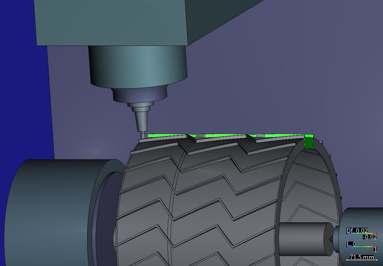
The finished pitch the run with the error terms on (marked) recorded, put back on the canvas with its
Diff, and the parking program NC/pose-b-edge.nc played on it: T2, the Ø10 three-flute flat end mill in
its shrink-fit holder, stands on the floor at the outboard end of the groove, X −201. Spindle nose, holder
and cutter above; the rotary table's faceplate and stator ring on the left; the Ø80 mandrel and the
tailstock centre at the lower right. Next to the cutter lies the faceplate end of the floor, its skin
17 µm thinner, but this camera looks level at the groove's end and the near grouser hides the floor; the
Diff faces in view are green (near 0). The orange-red of the faceplate end shows in the top and oblique
Diff pictures below. The “L.” colour bar at the lower right is not part of the Diff. Diff colour range
±0.02 mm: red = cut too deep, blue = material left, green = 0, both signs weighted alike. A HiNC 3.2.46
development build with error-term branches, 0.125 mm.
| The whole groove at 0.125 mm on a HiNC 3.2.46 development build with error-term branches | Predicted before the first play | Measured |
|---|---|---|
| Tip minus the nominal tip minus δ, all 71,562 steps | 0 (the plan allowed 1×10⁻⁹ mm) | largest 4.07×10⁻¹³ mm |
| Largest tip offset on a cutting step | 17.98 ± 0.1 µm | 17.9803 µm, T1 entering at x −206 |
| Machine coordinates X, Y, Z, A, marked against nominal | the same | bit-identical at every step |
| Groove floor, medians of forty 10 mm bins | x·sin α | within 0.0183 µm of x·sin α; line fit 1.00001·sin α, intercept 0.0007 µm |
| Skin at the faceplate end (x −200…−199) / at the tailstock end (x 199…200) | x·sin α: 0.7325 / 0.7675 mm at x ∓200, 0.7326 / 0.7674 mm at the windows' median x | 0.7326 / 0.7674 mm |
| Walls facing the faceplate, top 0.5 mm, long / short segment | −h·sin α·nₓ: +0.266 / +0.496 µm (the plan: at most 0.27 / 0.51 µm at the top) | +0.265 / +0.494 µm |
| Walls facing the tailstock, top 0.5 mm, long / short segment | −h·sin α·nₓ: −0.266 / −0.496 µm | −0.264 / −0.494 µm |
| Grouser tops, bore, rims and ring | 0 | within 5.1×10⁻¹⁰ mm |
| Trimmed (0.25 mm): mark cleared against marked | bit-identical | bit-identical: 11 series, Diff--Stats, 3,139,116 vertices |
| Control against nominal | 0 | series bit-identical; vertices p01 / p99 ±4.8×10⁻¹⁰ mm, every vertex within 9.31×10⁻⁷ mm once 15 search artefacts are rechecked exactly |
| Server time and peak memory of a whole-groove run | the plan's estimate: 10–15 min, 15–22 GB | 9.6–12.6 min, 11.13–17.06 GB |
The case
The wheel's own case page tells how the agent rebuilt the wheel from published numbers and a photograph, generated the machine, wrote the four-axis programs and accepted them. This page starts from that accepted project. What the agent was given:
- The accepted project and its programs.
- The stock is one tread pitch across the full width, between the centre lines of grousers 9 and 10, its inside already turned. Program zero is on the A axis at mid-width, G54 (0, 0, −670); the tool lengths are H1 105 and H2 100.
- The two programs of the case's
Full revlist, FanucG43 Hprograms that position X, Z and A with Y0 in every block and cut from x −206 to +206:NC/1-rough-T1-slow-full.nc(T1, Ø12, 1,037 lines, two levels at R 246.5 and R 243.0, its full-slot moves already slowed to 60 % feed) andNC/2-finish-T2.nc(T2, Ø10, 512 lines, the floor at R 242.5 and the walls). - Their trimmed versions,
NC/trim-1-rough-T1-slow-full.nc(491 lines) andNC/trim-2-finish-T2.nc(281 lines): the same strategy stopped at x −50, that is the outboard 150 mm, with the first chevron bend and the stretch over the stiffening ring. - The machine
Generic-4X-A, chain[O][base][Y][X][A][w];[base][Z][S][t]: the A axis 330 mm above the table, the faceplate's face at x −280 and the tailstock centre at x +251, 531 mm apart. The faceplate hangs on the A anchor, the tailstock body on the X anchor.
- HiNC's error terms. An axis or the spindle of the machine chain can be given an error term, a static branch of its own just before the axis's branch: it carries
an error measured on the real machine rather than part of its design. The controller,
XyzabcSolver, which turns NC into machine coordinates, RTCP and tilted planes included, always solves on the nominal chain, taking the marked branches as absent. While the project's Enable Error Terms switch is on, the simulated machine keeps the marked branches as it moves, cuts and checks collisions. So the error is cut into the part, as on a real machine whose controller does not know it. Each step's machine coordinates are the same with the switch on and off; the tool tip, the cut and the collisions differ. A program without RTCP or a tilted plane does not read the chain at all, so every error in the chain, marked or not, is cut into the part (Error-Term Branches). - Touch-off and P0. HiNC's P0 measures program zero on the nominal chain. On a real machine, the G54 found by touching off already holds the constant shift the error causes at the touch-off pose; to reproduce a given shop's cut, the manual advises typing in the work offset that shop measured (Work offsets on a machine with error terms).
- A placement rule. HiNC's product owner ruled on 2026-10-06 that an error term goes only directly
upstream of a role branch, an axis X … C or the spindle, on an anchor of its own named after the axis
(
<axis>err). - The request. HiNC's product owner asked for error-term showcases built on accepted cases, with the heavy runs on a shared server.
What nothing states:
- Which error to put in. The first suggestion, an offset of the A axis' centre of rotation that would make the skin vary round the wheel, is taken up whole by a G54 found on the A axis in this set-up (dilemma 1). The agent took an orientation error instead, which a touch-off cannot take out.
- How far this machine's A axis is tilted, and which way. The machine is a generic one built for these case studies, so there is no measurement to cite, and no maker's figure for how well a rotary table and its tailstock line up with the X travel was found. The agent took 0.005° and chose the sign with the tailstock end low.
- What a touch-off would find. It has to be derived from the chain: with the pivot at the touch-off point, the G54 a touch-off finds lies within 2.25 µm of the case's own, so no work offset was typed in (dilemma 2).
- Whether a 0.125 mm grid reads it. The largest deviation, 17.5 µm, is 14 % of a cell; the 0.5 µm on the walls is 0.4 % (dilemma 5).
What is new here:
- The error a touch-off leaves in. On a rotary axis that carries program zero, the axis' position error goes into the work offset; its orientation error stays, and here it becomes a taper across the width.
- A rotary axis without RTCP. Unlike the
forged wheel and the
NIST frustum, whose
G43.4programs let a calibrated controller cut the nominal part again, these positioning programs leave a controller that knows the error nothing to correct. - The skin as the gauge. The floor of the groove is the skin's outer face and the bore is not cut, so the floor's deviation is the change of the skin's thickness: 0.7326 to 0.7674 mm from end to end.
What the agent built
Each value is marked read (from the base case or the documentation), derived (computed from what was read), chosen (the agent's decision) or measured (read back after the build).
| Item | Value | Source |
|---|---|---|
| What the error is | The A axis, the line through the faceplate and tailstock centres, tilted about Y in the XZ plane against the X travel: ISO 230-7's EB0A, the orientation error of the A axis about Y. The sign is chosen with the tailstock end low | chosen: the kind of error and its sign; derived: the ISO name |
| Size | α = 0.005° (87.27 µrad, sin α = 8.7266×10⁻⁵): over the 531 mm between the centres, the tailstock end 46.3 µm below the faceplate end; on the wheel, 17.45 µm at x ±200 | chosen: a typical value for the tilt of a rotary axis, since this generic machine was never measured; derived: 46.3 and 17.45 µm |
| Where it sits | Directly upstream of the A axis branch. The segment X→A is split in two: X→Aerr, named EB0A, carries a Static Rotation of 0.005° about (0, 1, 0) with the pivot (0, 0, 572.5) in the X anchor's frame and is marked as an error term; the A axis' Dynamic Rotation (axis (−1, 0, 0), pivot (0, 0, 330)) moves whole onto Aerr→A, and Axis A is bound to it again with its values unchanged |
chosen, following the owner's ruling of 2026-10-06 |
| Pivot | (0, 0, 572.5): the groove floor, R 242.5, at mid-width at A 0, which is the touch-off point; the deviation there is 0 at every A | chosen: the touch-off assumption; derived: the coordinates |
| Machine chain | [O][base][Y][X][Aerr][A][w];[base][Z][S][t]: X →EB0A→ Aerr →A→ A →table-mount→ w |
measured: read back after the build |
| Read back | The values requested equal those read back (axis, angle, pivot); the other 7 branches kept their names, ends, kinds, roles and guids; the roles check was empty before and after the build; loading and reloading gave no message | measured |
| Work offset | All seven runs use the case's own G54 (0, 0, −670); nothing is typed in | derived: a touch-off would find it within 2.25 µm (dilemma 2) |
Why EB0A rather than the suggested offset of the centre? The designer agent, the agent that drafted this study, compared the candidates:
- A position error goes into the work offset. Program zero lies on the A axis, at mid-width on its centre line, and for such work a shop always finds G54's Y and Z on the A axis. A position error of the A axis (EY0A, EZ0A) is then taken up whole by the work offset, the same at every A. Even without a touch-off it would only make the skin evenly thinner, or the groove evenly offset, all round the wheel; it would not vary round it.
- A variation round the wheel needs the part held off-centre: a run-out of the fixture or the mandrel, not an error of the machine, and the manual allows no error term on a fixture or a workpiece.
- A squareness of X to Y or to Z moves the A axis and the wheel with X, so the wheel's axis stays parallel to the X travel: about 0. A tilt of Z or of the spindle changes a flat end mill's bottom by at most 0.5 µm across Ø10–Ø12. EC0A, the A axis' tilt in the horizontal plane, only twists the groove round the wheel and leaves the skin alone.
- What stays in the 0.75 mm skin, and no touch-off removes, is the orientation of the A axis against the X travel: the tool runs along X at the programmed height, the wheel's axis sinks toward one end, and the skin thickens linearly across the width.
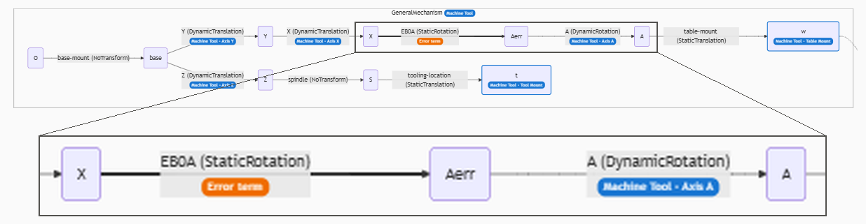
The machine-tool cluster (GeneralMechanism) in the Topology column of the Equipment page. A new anchor, Aerr, now stands between X and A. EB0A, the Static Rotation on X → Aerr (recorded value 0.005° about (0, 1, 0), pivot (0, 0, 572.5) mm), is drawn thick with the orange “Error term” badge; the A axis' Dynamic Rotation now runs from Aerr to A and is still bound to Axis A. Below, the X → Aerr → A stretch of the same capture, magnified 2.6 times. A HiNC 3.2.46 development build with error-term branches, English interface.
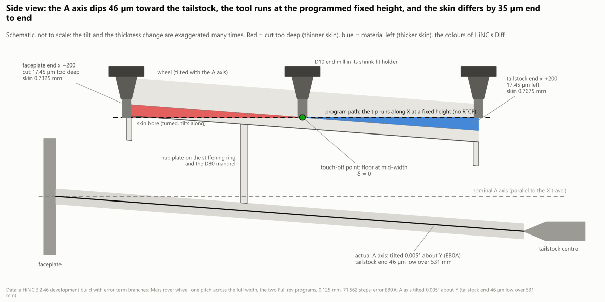
Side view, not to scale, the tilt and the change of thickness exaggerated: faceplate, mandrel, wheel and tailstock centre; the actual A axis tilted 0.005° about Y (the tailstock end 46 µm low over 531 mm, ISO 230-7 EB0A). The tool runs along X at the programmed fixed height; at the touch-off point, the floor at mid-width, the deviation is 0; the faceplate end is cut 17.45 µm too deep (skin 0.7325 mm) and the tailstock end keeps 17.45 µm (skin 0.7675 mm). Red = cut too deep, blue = material left, as in the Diff.
Where the tip goes: the prediction written in the plan.
- Notation: α = 0.005°; X, Y, Z are the nominal run's tip in program coordinates, which are the wheel's coordinates (x along the width, 0 at mid-width); A is the machine's A in degrees; ρ = Z·cos A − Y·sin A is the program's Z, the tip's distance from the A axis; z0 = 242.5 is the pivot's height above the A axis.
- The controller puts the tip at (x, 0, ρ) as programmed, while the real wheel turns about an axis tilted by α. In wheel coordinates the tip is then off by δ = R_A⁻¹ (R_y(−α) − I)(T − c). Written out, the radial part is Δz = X·sin α + (ρ − z0)(cos α − 1), the axial part Δx = X(cos α − 1) − (ρ − z0)·sin α, the tangential part 0, and δ = (Δx, −Δz·sin A, Δz·cos A).
- The radial part is almost exactly x·sin α: toward the faceplate end (x < 0) the tip goes further toward the wheel's centre and cuts deeper; toward the tailstock end (x > 0) it stops short and leaves material. The axial part, −(ρ − 242.5)·sin α, is 0 on the floor and grows with height: at most 0.35 µm on the cutting steps, 28.6 µm on the moves at tool-change height, ρ 570.
- On the cutting steps |δ| ≤ 17.98 µm, at x = ±206 at the groove's ends; on all steps ≤ 34.2 µm, at tool-change height and x −215. At the touch-off point (x 0, ρ 242.5) δ = 0.
- The machine coordinates MC.X/Y/Z/A of every step are the nominal run's, bit for bit (no RTCP).
What the part keeps is the component of δ along the surface normal (first order, in proportion to α):
- Groove floor, that is the skin: Δt(x) = x·sin α, changing with x only and not round the wheel, so the Diff's colour bands run square to the wheel's axis. At the faceplate end, x −200, 17.45 µm too deep (skin 0.7325 mm); at mid-width 0; at the tailstock end, x +200, 17.45 µm left (skin 0.7675 mm). At the outermost and innermost measuring lines of the base case's skin script, x −193.9 and +192.1: −16.92 / +16.76 µm.
- Walls (the sides of the chevron grousers, cut by the side of the tool): relative to the wheel, the tool, and with it the wall it cuts, moves along the axis by −h·sin α, toward the faceplate, where h is the height above the floor (0–7.5 mm); a wall keeps that times the axial component of its normal, sin φ (design values at R 242.5: 0.414 for the long 24.4° segments, 0.781 for the short 51.3° ones). At the wall top that is at most 0.27 / 0.51 µm: walls facing the faceplate keep material, walls facing the tailstock are cut deeper. The radial component slides along the wall and does not move it.
- Grouser tops (the stock's R 250 face), the two end faces, the bore, the rims and the ring: 0.
- Mark cleared: bit-identical to the marked run.
- Collisions: the tilt takes the faceplate further from the stator ring (+7…+35 µm) and moves the mandrel's end 21 µm relative to the tailstock centre; the tool assembly keeps its distance from the fixture and the machine (at least 87.8 mm), so no new collision is expected.
The runs:
| Run | List | Grid | Error-term switch | EB0A | Purpose |
|---|---|---|---|---|---|
| t-nominal | Trimmed rev | 0.25 mm | off | marked (not in effect) | trimmed: nominal; exports the trimmed nominal cut |
| t-control | Trimmed rev | 0.25 mm | off | marked (not in effect) | trimmed: control; Diff |
| t-unmarked | Trimmed rev | 0.25 mm | on | mark cleared | trimmed: the controller knows the error; Diff, cut exported |
| t-on | Trimmed rev | 0.25 mm | on | marked | trimmed: the controller does not know it; Diff, cut exported |
| f-nominal | Full rev | 0.125 mm | off | marked (not in effect) | exports the nominal cut, the ideal geometry |
| f-on | Full rev | 0.125 mm | on | marked | the controller does not know the error; Diff, cut exported |
| f-control | Full rev | 0.125 mm | off | marked (not in effect) | Diff, cut exported: the noise floor |
Common to every run:
- Physics off. This case is about geometry only; cutting force and deflection are outside it. The base case's acceptance ran with physics on, so its cost does not compare with this one's.
- Collision detection on, without pausing on a failure; each step is one spindle revolution (Feed Per Cycle).
- G54 (0, 0, −670) in all seven runs; no work offset typed in.
- The geometry difference (Geometry Validation): detection radius
1 mm, colour range (
DiffVisualRadius) ±0.02 mm. - The per-step series recorded: Cl.X/Y/Z, MC.X/Y/Z/A, FileNo, LineNo, IsTouched and ToolId.
How the agent managed the work
- Criteria and predictions first. The plan, its predictions and seven numbered criteria were committed before the first play, which started at 21:57:28 on 2026-10-06.
- Trimmed runs first. The
Trimmed revlist, the outboard 150 mm, ran four times at 0.25 mm, 29,525 steps each: nominal, control, mark cleared and marked. They checked the build, the per-step formula, and that the run with the mark cleared equals the marked one. - Three whole-groove runs, one at a time. The
Full revlist ran at 0.125 mm, the case's acceptance grid with six cells through the skin, 71,562 steps each: nominal (exporting its cut), marked (Diff and export) and control (Diff and export).- Before each run the instance was restarted and the project reloaded from its file, so every run is the first of its instance.
- The nominal and the marked run played back to back on 2026-10-06; the control run played about four hours later, at 02:37 on 2026-10-07.
- The plan's stop rule, falling back to 0.25 mm if a run passed 40 GB, was never reached.
- The nominal cut as the ideal geometry. The nominal run exported its cut, about 8.14 million triangles (the trimmed nominal run its own), and that cut became the ideal geometry of every Diff, with a 1 mm detection radius. The Diff then shows only what the error changes, not the marks the toolpath itself leaves.
- Played from the NC, not from a record. The case's mission held a nested Record Meshed Geometry entry that writes the finished stock to a record file; it was switched off. Each run with a Diff recorded its own final stock instead, for the pictures.
- Numbers from the records. An analysis script computes the numbers on this page from the run records and keeps each with its source, so the analysis can be run again. The groove floor, the walls, the grouser tops, the end faces and the bore are picked out with the design geometry of the base case's own wheel script, and the floor statistics leave out the points within 1.5 mm of a wall, as the base case's skin-measuring script does. The vertices the distance search read farthest off were rechecked exactly against the nominal cut.
- Pictures in both interface languages, taken by putting a run's recorded stock back on the canvas with its Diff; no run was played again for them.
- Sharing a server. Every run played on a private instance on a shared 32-thread server.
- Where a person stepped in. HiNC's product owner asked for error-term showcases built on accepted cases, with the heavy runs on the shared server, and ruled that an error term goes only directly upstream of an axis or the spindle, one marked static branch per error. The kind of error, its size and sign, the pivot, the predictions and the criteria are the agent's.
The dilemmas
Each one is told as its situation, the risk had it been missed, how it was noticed, the resolution, and the evidence that the resolution held.
1. The suggested error would vanish into the touch-off
- Situation. The first proposal was an offset of the A axis' centre of rotation, to make the skin vary round the wheel.
- Risk. Program zero lies on the A axis, and a shop always finds G54's Y and Z there. A translation d upstream of A is then taken up whole by the work offset (in δ = R_A⁻¹(T − P0 − d), the G54 cancels d), and nothing would show on the part. Even without a touch-off the skin would only come out evenly thinner all round, not varying round the wheel; a variation round the wheel is a run-out of the fixture or the mandrel, which the manual does not allow as an error term.
- How noticed. The designer agent derived what a touch-off would find.
- Resolution. An orientation error, EB0A, instead: it becomes a taper across the width, which no touch-off takes out.
- Evidence. The floor's deviation changes with x only: its term round the wheel is 2.9×10⁻⁶ µm per degree. The 20 steps around the touch-off point are off by 0.0016–0.0374 µm, exactly |x|·sin α, and every step lies within 4.07×10⁻¹³ mm of the formula. That a position error would vanish into G54 is the design's derivation; it was not played.
2. Where the pivot sits is an assumption about the touch-off
- Situation. A Static Rotation needs a pivot. Taken literally, “the faceplate centre right, the tailstock low” puts it at the faceplate centre, (−280, 0, 330).
- Risk. With the pivot in the wrong place, the part carries an extra constant shift and looks as if program zero were wrong.
- How noticed. The designer agent's derivation: a pivot at the faceplate centre equals this case's tilt plus a constant shift of (+21.2, 0, −24.4) µm, exactly what a touch-off at mid-width would take into G54.
- Resolution. The pivot sits at the touch-off point, the floor R 242.5 at mid-width at A 0, (0, 0, 572.5) in the X anchor's frame. The deviation there is 0 at every A. A touch-off itself finds a G54 within 2.25 µm of the original: Z, touched on the stock top at mid-width, reads a radial difference of about 0, that point moving only −0.65 µm along X; X, touched on the outboard end face, reads −0.65…+2.25 µm. So all seven runs keep the original (0, 0, −670), nothing typed in. The page states the assumption: had the shop found the A axis' centre at the faceplate end instead, the part would only carry an extra constant shift, and the taper would stay the same.
- Evidence. The 20 steps around the touch-off point are off by 0.0016–0.0374 µm, exactly |x|·sin α; over all steps the tip lies within 4.07×10⁻¹³ mm of the formula.
3. The tailstock body does not tilt
- Situation. The error sits between X and A: the faceplate, the fixture and the wheel tilt with it, while the tailstock body, which hangs on the X anchor, does not.
- Risk. A page saying “the tailstock moved 46 µm lower” would not match what the model shows; or a reader would fear the tailstock centre hitting the mandrel.
- How noticed. A doubt the designer agent recorded.
- Resolution. The error is described as the line through the two centres — the A axis — tilted against the X travel, which for the cut is the same as a low tailstock. In the pictures the tailstock stands at its nominal place; at the centre the difference is about 22 µm, too small to see. For collisions the design predicted the faceplate further from the stator ring, the mandrel's end moving 21 µm relative to the tailstock centre (it stands 1 mm from the centre), and the tool assembly at least 87.8 mm from the fixture and the machine.
- Evidence. None of the seven runs'
steporncmessages holds aCollision--Detected.
4. Whether to play the whole groove with the mark cleared
- Situation. The plan put the run with the mark cleared in the trimmed set only.
- Risk. One piece of evidence fewer on the whole groove; or another whole-groove run, 12 minutes at 17 GB, for a result known in advance.
- How noticed. The programs carry no
G43.4,G43.5orG68, and they are not CL: the controller does not read the machine chain, so the run with the mark cleared must equal the marked one bit for bit. Were it otherwise, that would be the finding to record. - Resolution. One run with the mark cleared, in the trimmed set. There is none on the whole groove and no capture of one, so this page has no “controller unaware / aware” alternation; the controller chart in the results shows the comparison instead.
- Evidence. In the trimmed set the two runs have bit-identical per-step series (all 11 keys),
Diff--Statsand exported-cut distances.
5. Can a 0.125 mm grid read the real 0.005°?
- Situation. The largest deviation, 17.5 µm, is 14 % of a cell; the 0.5 µm on the walls is 0.4 %. The designer agent kept a display value ten times larger (0.05°, ±174.5 µm at the ends) in reserve.
- Risk. Pictures that show no gradient, or numbers lost in the noise of the voxels.
- How noticed. The designer agent cited a 0.25 mm trial run on another case of this batch, where an X–Y squareness of 0.003° still read ±2.7 µm, and judged that the real value would show at 0.125 mm. This case ran no trial before the plan: the trimmed and whole-groove runs used the real value, and the results were read afterwards.
- Resolution. No enlargement. Every number and every picture shows the real 0.005°, at a colour range of ±0.02 mm. The tenfold value was never played.
- Evidence. The 40 bin medians of the floor meet the prediction within 0.0183 µm, the walls within 0.0027 µm; read off the Df colour bar along the floor of the top-view Diff, the colours give −0.015 mm at the left end and +0.017 mm at the right.
6. Criterion 5's filter is written too wide, and fails as written
- Situation. Criterion 5 takes "the floor vertices (radius < 242.6)".
- Risk. Taken literally, that also takes in the bore R 241.75, the rims, the ring and the lower part of the side faces, which are uncut and read d = 0: 3,194,957 vertices whose bin medians fall between 0 and the floor's value, up to 17.02 µm off the prediction, so the criterion fails for a reason that has nothing to do with the part.
- How noticed. Setting the criterion's filter beside the way the features are picked.
- Resolution. The verdict is written as failed (bins up to 17.02 µm off, slope 0.49·sin α, intercept +0.0245 µm). Separately, on the floor the criterion means — 242.4 ≤ r < 242.6, without the points within 1.5 mm of a wall, as the base case's skin script does — both definitions of the floor pass: the floor within 0.0183 µm and 1.00001·sin α; the whole floor band, the foot of the walls included, 0.018 µm and 0.9927·sin α. This is a finding about the plan, not a new verdict.
- Evidence. The bins and fits of the literal filter and of the two floor selections.
7. The extremes of the mesh distance are not the part
- Situation. The control reads −0.179 / +0.081 mm, the marked run −0.179 / +0.25 mm: ten times the largest predicted deviation, 17.45 µm.
- Risk. Read as the error, they would say the part was cut wrong; set aside without a check, the claim would not stand.
- How noticed. The rule that an extreme is rechecked with an exact point-to-mesh distance before anything is said about it.
- Resolution. Every vertex the search read beyond a threshold was rechecked against every triangle of
the nominal cut.
- The control's 15 vertices beyond 1×10⁻⁶ mm (−0.179…+0.081 mm) all lie on the stock's side faces, the pitch boundaries that no tool touched, and all are exactly 0. With the exact values, all 4,316,019 vertices lie within −8.62×10⁻⁷…+9.31×10⁻⁷ mm.
- Of the marked run's 284 vertices beyond 0.02 mm, 19 are exactly 0: 10 on the stock's side faces (the −0.179 mm among them, the same vertex with the same value as in the control) and 9 at x = −200, 2 on the end face and 7 on its edge with the floor (the +0.25 mm among them).
- They are artefacts of the distance search, which looks only at the 12 nearest triangle centroids: next to large triangles the centroids lie far from the vertex, and the face it lies on is not among the 12. The other 265 are real differences (dilemma 8).
- Evidence. The exact recheck of both runs. The analysis also rechecked the control's 13 vertices beyond 0.5 µm against the stock model: at most 2.24×10⁻⁶ mm, like the other uncut vertices.
8. A strip at the foot of the walls reads −84 µm
- Situation. In the floor band, 44,959 vertices lie 1.8–2.6 mm from a grouser's centre line. 265 of them read −83.74…+20.10 µm, 264 on the x < 0 half, where the marked run's floor lies below the nominal one, and 0.006–0.054 mm from the nominal floor.
- Risk. Read as a groove cut into the part.
- How noticed. Sorting the vertices by the kind of face they lie on.
- Resolution.
- Rechecked exactly against every triangle of the nominal cut, these 265 vertices read what the search read (within 4×10⁻⁹ mm): the two exported meshes really differ there.
- The difference exceeds the 18.82 µm the error's geometry allows (the geometric bound in the results), so the measurement and the reasoning disagree, and that is recorded as a finding.
- The likeliest cause is that the two runs extract this concave corner into different faces within the same 0.125 mm cell: half a cell's diagonal is 88 µm, and the differences sit almost all on the x < 0 half, where the floor lies lower. If so, it shows how the simulation's grid treats a concave corner, not a shape the error leaves on the part. The cause was not verified directly.
- The floor statistics leave out the points within 1.5 mm of a wall, as the base case's skin script does, so this strip does not enter them.
- Two more groups read off the prediction but stay under the 0.02 mm recheck threshold and were not rechecked: 39 floor vertices on the grid plane z = 241.000 (search values 0.5–7.6 µm above the prediction) and 91 vertices on the wall top edge (search values 2–18.2 µm).
- Evidence. All 284 vertices beyond 0.02 mm were rechecked: 265 real differences and 19 artefacts; the nearest control vertices lie 0.021–0.113 mm from the 265. The trimmed marked run (0.25 mm) was rechecked too, and the run with the mark cleared is identical to it: of 135 vertices beyond 0.02 mm, 15 are artefacts (11 on the stock's side faces, 4 on the end faces) and 120 are real, all in concave corners — 86 in the corner strip (x −199.5…−55.5, −124.96…−20.14 µm) and 34 at the step and corners the trimmed path leaves where it ends at x −50 (x −49.5…−44.0, −173.04…−20.03 µm). At both grids the real differences stay within half a cell's diagonal (0.125 mm: 88 µm; 0.25 mm: 177 µm), as the face-extraction explanation expects; that is still not a direct verification.
9. The largest offset falls on a grazing step, and the touch flag differs on 35 steps
- Situation. Criterion 3 asks the largest |δ| on the cutting steps to be 17.98 ± 0.1 µm, and the marked and the nominal run do not agree on every step about which steps cut.
- Risk. With the marked run's
IsTouched, the largest is 17.973 µm (step 16,808, T1 at the tailstock end, x +205.92, ρ 246.5): still within the tolerance, but “where the largest offset is” moves from the faceplate end (x −206) to the tailstock end. - How noticed. The step-by-step comparison.
- Resolution. Cutting steps are always taken from the nominal run's
IsTouched, the analysis' convention, and the 35 steps that differ are recorded: 28 touched only in the nominal run — 23 at the open outboard end (x −206.00…−197.63), 3 at the tailstock end (x +180.36…+202.88) and 2 at x −127.23 / −121.44 — and 7 only in the marked run, spread over x −193.86…+180.77 (6 of them T2). The step counts, program lines and machine coordinates are the same. - Evidence. The per-step comparison of the two runs' series.
Results and benefits
Unless stated otherwise, the numbers are the whole groove at 0.125 mm, error terms on (marked) against off, measured on a HiNC 3.2.46 development build with error-term branches, physics off; the trimmed runs are at 0.25 mm. “Measured” here means measured on HiNC's simulated results.
The plan's seven criteria
Five of the seven criteria passed and the cost was recorded; criterion 5 failed as written, because its filter takes in uncut faces, and passes on the groove floor it means (dilemma 6).
| # | Criterion, in short | Verdict | Measured |
|---|---|---|---|
| 1 | Build: the chain X → EB0A → Aerr → A → A → table-mount → w; EB0A marked as an error term and read back as written; the A axis' values unchanged, Axis A bound to it; the roles check empty; the case's files outside the error-term folder unchanged | passed | The chain as above; EB0A a Static Rotation about (0, 1, 0), 0.005°, pivot (0, 0, 572.5), marked, its values read back as requested; A moved onto Aerr → A with its axis (−1, 0, 0) and pivot (0, 0, 330) unchanged and its role Axis A (that branch has a new guid); the other 7 branches unchanged in name, ends, kind, role, mark and guid; the roles check empty before and after the build; no message on loading or reloading; after the build and the seven runs, git found no change to the case's files outside the error-term folder |
| 2 | Every run ends Finished, plays its programs to the last line and collides with nothing; only the expected Diff--TargetNotClosed is added |
passed | All seven Finished; each program played to its last G0 line (roughing line 1,033 of 1,037, finishing 508 of 512; trimmed 487 of 491 and 277 of 281; after them only M9, M5, M30 and %); IsTouched peaks at 1; the nc, step and ncManip sinks empty, no Collision--Detected; the shell sink holds one Diff--TargetNotClosed in each of the five runs with a Diff (the ideal geometry is an exported open mesh) and none in the two nominal runs |
| 3 | Marked: on every step |Cl − Cl(nominal) − δ| ≤ 1×10⁻⁹ mm; the machine coordinates the nominal's at every step; the largest |δ| on a cutting step 17.98 ± 0.1 µm | passed | All 71,562 steps within 4.07×10⁻¹³ mm (components 9.7×10⁻¹⁴ / 6.2×10⁻¹⁴ / 4.1×10⁻¹³ mm); MC.X/Y/Z/A bit-identical; on the nominal run's 67,996 cutting steps the largest |δ| is 17.9803 µm. Trimmed marked run: within 3.77×10⁻¹³ mm, and 17.9803 µm |
| 4 | Control: Cl bit-identical to the nominal; at least 99 % of the vertices within 0.5 µm of the nominal cut | passed | All 11 series keys (Cl, MC, FileNo, LineNo, IsTouched, ToolId) bit-identical, in the trimmed set too; 99.9997 % of 4,316,019 vertices within 0.5 µm, the other 13 on the stock's side faces and exactly 0 against the nominal cut (dilemma 7), so 100 % with the exact values; p01 / p99 ±4.8×10⁻¹⁰ mm |
| 5 | Skin taper: the marked run's floor vertices (radius < 242.6) against nominal, binned every 10 mm in x: medians = x·sin α ± 1.5 µm; a fitted line's slope within sin α × (1 ± 5 %), its intercept |b| ≤ 1 µm | as written: failed; on the groove floor: passed | As written (radius < 242.6: 3,194,957 vertices, which take in the uncut bore, rims, ring and lower side faces at d = 0): the 40 bin medians up to 17.02 µm from x·sin α at the bin centre (tolerance ±1.5 µm), slope 0.49·sin α (tolerance ±5 %), intercept +0.0245 µm: failed. The cause is a filter written too wide (dilemma 6); not re-judged. On the floor the criterion means (242.4 ≤ r < 242.6, at least 1.5 mm from a wall, 1,505,688 vertices): bin medians within 0.0183 µm, slope 1.00001·sin α, intercept 0.0007 µm; the whole floor band, foot of the walls included (1,618,280 vertices): 0.018 µm, 0.9927·sin α, −0.0067 µm |
| 6 | Mark cleared (trimmed): Cl and MC bit-identical to the marked run | passed | All 11 series keys of the two runs equal; their Diff--Stats, eight numbers, equal; the exported cuts' vertex coordinates and distances bit-identical |
| 7 | Cost: the wall clock and VmHWM of every run | recorded | See What the runs cost below |
The designer agent's own acceptance checks were judged too, five of them; the base case's radial measuring lines themselves, holes in the skin, values after saving and reloading, the simulated machining time and the exported mesh's triangle count and size were not judged, and the bore and the colours of the Diff pictures are covered in the results.
| Check | Verdict | Measured |
|---|---|---|
| Diff NaN leaves ≤ 0.1 % | passed | marked 127 of 4,651,503 = 2.7×10⁻⁵; control 4.5×10⁻⁶; trimmed marked and mark-cleared runs 7.1×10⁻⁶; trimmed control 4.4×10⁻⁶ |
| Walls, |d| p99 ≤ 2 µm | passed | 0.489 µm (623,077 vertices) |
| Grouser tops and both end faces, |d| ≤ 1 µm | as written: failed (on the edge where an end face meets the floor); grouser tops passed; end faces away from the groove's edge passed | Judged vertex by vertex. Grouser tops: 122,093 vertices, |d| ≤ 5×10⁻¹⁰ mm. End faces away from the groove's edge, 8,204 vertices: the 2 that read +0.125 / +0.25 mm are exactly 0 against the nominal cut (dilemma 7), the rest read 0…+0.31 µm (search values, an upper bound on |d|, so ≤ 1 µm holds vertex by vertex). The edge where the end face meets the floor (2,402 vertices) rises with the floor at x +200: search p99 +17.47 µm (not rechecked; the floor reads +17.45 µm there). The design's “end faces 0” missed this edge, which is recorded as a finding about the plan. The edge also holds 7 search artefacts of +0.125 mm at x = −200, exactly 0 |
| Outermost / innermost measuring line −16.9 / +16.8 ± 2 µm | passed | Measured as a stand-in, the median of the floor vertices within ±1 mm rather than the base case's radial lines: −16.922 µm at x −193.9, +16.762 µm at x 192.1 (predicted −16.921 / +16.764) |
| Floor fit residual p95 ≤ 2 µm, p99 ≤ 5 µm | passed | 0.012 / 0.014 µm (a stand-in as well: a line fitted through the floor vertices, not the radial lines) |
The tool tip: every step on the formula
The tool tip here is each step's Cl: the actual tip in program coordinates, which are the wheel's
coordinates. All runs have the same number of steps, with the same FileNo, LineNo and ToolId at
every step, so they are lined up by step and subtracted. A cutting step is a step on which the nominal run
touched the stock (IsTouched 1): 67,996 steps, T1 40,307 and T2 27,689; 3,566 steps touch nothing.
| Comparison | Over | Result |
|---|---|---|
| Marked minus nominal, minus δ | all 71,562 steps | within 4.07×10⁻¹³ mm in length; components 9.7×10⁻¹⁴ / 6.2×10⁻¹⁴ / 4.1×10⁻¹³ mm |
| The same | the 67,996 cutting steps | within 3.77×10⁻¹³ mm |
| Marked minus nominal, length of the offset | cutting steps | largest 17.9803 µm: step 534, T1 entering at x −206, ρ 246.5, A 10.72° (program 1, line 13); on T2's floor at most 17.882 µm |
| The same | all steps | largest 34.188 µm: step 42,575, T2's move at tool-change height, ρ 570, x −215 |
| Radial part | cutting steps | −17.977 to +17.970 µm, which is x·sin α |
| Axial part | cutting steps | −0.350 to +0.001 µm, which is −(ρ − 242.5)·sin α |
| Tangential part | all steps | ≤ 1×10⁻¹³ mm (predicted 0) |
| Around the touch-off point (T2 on the floor, |x| < 0.5 mm) | 20 steps | 0.0016–0.0374 µm (predicted |x|·sin α: these 20 steps lie within |x| ≤ 0.43 mm, so ≤ 0.0374 µm; 0 at x = 0) |
| Machine coordinates MC.X/Y/Z/A, marked minus nominal | all steps | bit-identical (so are the control and the trimmed marked, mark-cleared and control runs) |
| Control minus nominal | all steps | 0: the 11 series keys bit-identical |
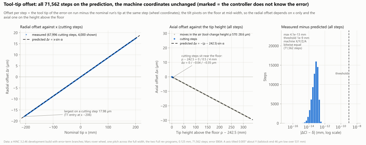
Error terms on (marked) minus nominal, 71,562 steps. Left: the radial offset against x; the cutting steps lie on x·sin α (largest 17.98 µm, T1 entering at x −206). Middle: the axial offset against the tip's height above the floor, following −(ρ − 242.5)·sin α (cutting steps −0.350…+0.001 µm, the moves at tool-change height −28.6 µm). Right: a histogram of measured minus predicted, at most 4.1×10⁻¹³ mm, against the plan's threshold of 1×10⁻⁹ mm. The machine's X, Y, Z and A are bit-identical. Symmetric axes. A HiNC 3.2.46 development build with error-term branches.
IsToucheddiffers on 35 steps. 28 touched only in the nominal run: 23 at the open outboard end (x −206.00…−197.63), 3 at the tailstock end (x +180.36, +202.75, +202.88) and 2 at x −127.23 / −121.44. 7 touched only in the marked run, spread over x −193.86…+180.77 (6 of them T2). These are grazing steps, a hair from touching the stock or not; the step counts, program lines and machine coordinates are the same. The step with the largest offset on a cutting step, 17.980 µm (T1 entering at x −206), is one the marked run does not count as cutting; criterion 3 takes the nominal run'sIsTouchedand is judged as written (dilemma 9).- The trimmed runs meet the formula as closely as the whole groove: the trimmed marked run within 3.77×10⁻¹³ mm, with the same largest offset, 17.9803 µm, on the same step. The per-step formula can be proved on the 0.25 mm trimmed case; the part and the pictures need the whole groove at 0.125 mm.
The part: the groove floor is the skin
How it was measured: the marked run's exported cut has 4,313,736 vertices, and each one was given its signed distance d to the nominal cut (positive = material left, blue in the Diff; negative = cut too deep, red). The floor is the vertices at 242.4 ≤ r < 242.6 mm and at least 1.5 mm from a wall, 1,505,688 of them, keeping off the foot of the walls as the base case's skin-measuring script does. The bore, R 241.75, is not cut and reads 0 in every run, so the skin's thickness is the design's 0.75 mm + d.
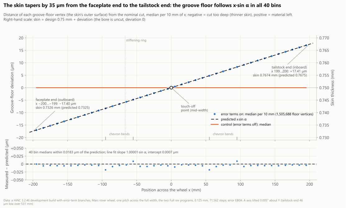
The main result. The distance of the groove-floor vertices (the skin's outer face) from the nominal cut, across the width x: the marked run's median per 10 mm (blue dots, 40 bins) lies on the prediction x·sin α (dashed); the control (orange) is 0; the right-hand scale is the skin's thickness (design 0.75 mm + deviation); the touch-off point, the stiffening ring and the chevron bends are marked. Below, measured minus predicted, at most 0.0183 µm. Symmetric ±20 µm axis, 0.125 mm grid, a HiNC 3.2.46 development build with error-term branches.
| Quantity | Measured | Predicted |
|---|---|---|
| Largest difference of a 10 mm bin's median from x·sin α at the bin's centre, 40 bins | 0.0183 µm (in a bin that holds a chevron bend, where the vertices are not spread evenly over the bin; against each bin's median x, at most 0.0093 µm) | 0 |
| Line fit d = s·x + b | s = 1.00001·sin α (8.7267×10⁻⁵), b = 0.0007 µm; residual |r| p95 0.012 µm, p99 0.014 µm | s = sin α, b = 0 |
| Term round the wheel (d = s·x + c·θ + b) | c = 2.9×10⁻⁶ µm per degree | 0 |
| x −200…−199 (faceplate end) | −17.404 µm, skin 0.7326 mm (3,878 vertices) | −17.41 µm at the window's median x; −17.453 µm at x = −200, skin 0.7325 mm |
| x 199…200 (tailstock end) | +17.406 µm, skin 0.7674 mm (3,892 vertices) | +17.404 µm at the window's median x; +17.453 µm at x = +200, skin 0.7675 mm |
| The two end bins of 10 mm | −17.017 / +17.013 µm | −17.017 / +17.017 µm |
| Outermost / innermost measuring line, x −193.9 / +192.1 (±1 mm) | −16.922 / +16.762 µm | −16.921 / +16.764 µm |
| The whole floor, p01 / p99 | −17.106 / +17.111 µm | x·sin α between −17.45 and +17.45 µm |
| The whole floor, extremes | search values −17.458 / +17.548 µm (not rechecked) |
Each point of the design's prediction table (median within x ±0.5 mm, µm; skin in mm)
| x (mm) | Vertices | Measured | Predicted x·sin α | Skin, measured | Skin, predicted |
|---|---|---|---|---|---|
| −200 (−200…−199) | 3,878 | −17.404 | −17.453 | 0.7326 | 0.7325 |
| −150 | 4,229 | −13.090 | −13.090 | 0.7369 | 0.7369 |
| −100 | 4,366 | −8.727 | −8.727 | 0.7413 | 0.7413 |
| −66.7 (over the stiffening ring) | 3,540 | −5.819 | −5.821 | 0.7442 | 0.7442 |
| −50 | 4,366 | −4.363 | −4.363 | 0.7456 | 0.7456 |
| 0 (the touch-off point) | 4,239 | 0.000 | 0 | 0.7500 | 0.7500 |
| +50 | 4,373 | +4.364 | +4.363 | 0.7544 | 0.7544 |
| +100 | 4,382 | +8.727 | +8.727 | 0.7587 | 0.7587 |
| +150 | 4,243 | +13.091 | +13.090 | 0.7631 | 0.7631 |
| +200 (199…200) | 3,892 | +17.406 | +17.453 | 0.7674 | 0.7675 |
The end windows' predictions are x·sin α at x = ±200; the windows' vertices have a median x about 0.5 mm inside ±200, where x·sin α is −17.41 / +17.40 µm.
The 40 bins of 10 mm (groove floor at least 1.5 mm from a wall; µm)
| x bin | Vertices | p01 | Median | p99 | Predicted (bin centre) | Median − predicted |
|---|---|---|---|---|---|---|
| −200…−190 | 38,110 | −17.439 | −17.017 | −16.594 | −17.017 | +0.000 |
| −190…−180 | 38,209 | −16.577 | −16.150 | −15.721 | −16.144 | −0.006 |
| −180…−170 | 37,923 | −15.703 | −15.276 | −14.848 | −15.272 | −0.005 |
| −170…−160 | 37,736 | −14.831 | −14.404 | −13.976 | −14.399 | −0.005 |
| −160…−150 | 37,633 | −13.960 | −13.532 | −13.104 | −13.526 | −0.005 |
| −150…−140 | 37,636 | −13.087 | −12.659 | −12.231 | −12.654 | −0.005 |
| −140…−130 | 37,730 | −12.214 | −11.785 | −11.358 | −11.781 | −0.004 |
| −130…−120 | 37,912 | −11.340 | −10.911 | −10.484 | −10.908 | −0.002 |
| −120…−110 | 38,202 | −10.467 | −10.039 | −9.613 | −10.036 | −0.004 |
| −110…−100 | 38,583 | −9.596 | −9.168 | −8.741 | −9.163 | −0.005 |
| −100…−90 | 37,693 | −8.724 | −8.309 | −7.869 | −8.290 | −0.018 |
| −90…−80 | 35,534 | −7.851 | −7.426 | −6.996 | −7.418 | −0.008 |
| −80…−70 | 35,145 | −6.977 | −6.549 | −6.120 | −6.545 | −0.004 |
| −70…−60 | 35,525 | −6.104 | −5.675 | −5.249 | −5.672 | −0.003 |
| −60…−50 | 37,659 | −5.233 | −4.791 | −4.377 | −4.800 | +0.009 |
| −50…−40 | 38,584 | −4.361 | −3.934 | −3.506 | −3.927 | −0.007 |
| −40…−30 | 38,196 | −3.489 | −3.062 | −2.633 | −3.054 | −0.008 |
| −30…−20 | 37,905 | −2.613 | −2.187 | −1.757 | −2.182 | −0.005 |
| −20…−10 | 37,717 | −1.739 | −1.312 | −0.884 | −1.309 | −0.003 |
| −10…0 | 37,624 | −0.869 | −0.442 | −0.015 | −0.436 | −0.005 |
| 0…10 | 37,786 | 0.000 | +0.427 | +0.854 | +0.436 | −0.009 |
| 10…20 | 37,876 | +0.878 | +1.307 | +1.734 | +1.309 | −0.002 |
| 20…30 | 38,062 | +1.751 | +2.179 | +2.606 | +2.182 | −0.003 |
| 30…40 | 38,323 | +2.622 | +3.051 | +3.478 | +3.054 | −0.004 |
| 40…50 | 38,720 | +3.494 | +3.922 | +4.349 | +3.927 | −0.005 |
| 50…60 | 37,819 | +4.366 | +4.781 | +5.220 | +4.800 | −0.018 |
| 60…70 | 35,682 | +5.239 | +5.665 | +6.096 | +5.672 | −0.008 |
| 70…80 | 35,301 | +6.114 | +6.542 | +6.969 | +6.545 | −0.004 |
| 80…90 | 35,667 | +6.986 | +7.415 | +7.841 | +7.418 | −0.003 |
| 90…100 | 37,763 | +7.858 | +8.300 | +8.713 | +8.290 | +0.009 |
| 100…110 | 38,728 | +8.729 | +9.155 | +9.586 | +9.163 | −0.008 |
| 110…120 | 38,343 | +9.603 | +10.031 | +10.459 | +10.036 | −0.005 |
| 120…130 | 38,031 | +10.477 | +10.904 | +11.332 | +10.908 | −0.005 |
| 130…140 | 37,865 | +11.349 | +11.776 | +12.205 | +11.781 | −0.005 |
| 140…150 | 37,764 | +12.221 | +12.649 | +13.076 | +12.654 | −0.005 |
| 150…160 | 37,762 | +13.092 | +13.521 | +13.950 | +13.526 | −0.006 |
| 160…170 | 37,848 | +13.967 | +14.395 | +14.822 | +14.399 | −0.004 |
| 170…180 | 38,051 | +14.840 | +15.269 | +15.695 | +15.272 | −0.003 |
| 180…190 | 38,328 | +15.712 | +16.141 | +16.567 | +16.144 | −0.003 |
| 190…200 | 38,713 | +16.585 | +17.013 | +17.440 | +17.017 | −0.004 |
Each bin's p01-to-p99 width, about 0.85 µm, is the range of x·sin α over the bin's 10 mm, not noise.
- The trimmed case agrees. The trimmed marked run against its own nominal cut, in the floor's 16 bins (x −200…−40): the medians lie within 0.014 µm of x·sin α at each bin's median x. Against the bin centres, the first 15 bins are within 0.023 µm (the largest at −100…−90); the last bin, −50…−40, is only half cut where the trimmed path ends, and reads 0.23 µm off. Slope 0.9997·sin α, intercept −0.0025 µm.
- 39 floor vertices read 0.5–7.6 µm above the prediction (search values, not rechecked; the search can overstate a distance). All lie on the line where the floor R 242.5 meets the grid plane z = 241.000 mm (wheel angle ±6.38°, x 6.9–82.9); every other grid plane that crosses the floor stays within 0.4 µm. Probably the two exported cuts sample that grid line differently; it does not show on the ±0.02 mm Diff pictures (dilemma 8).
- Why a 10 mm bin's median matches to 0.02 µm. The marked and the nominal run have bit-identical machine coordinates, so the tool stops at the same place at every step and only the whole wheel is offset by δ against it. The two exported cuts carry the same marks of the same steps, and the difference leaves only δ.
The part: the walls and the other faces
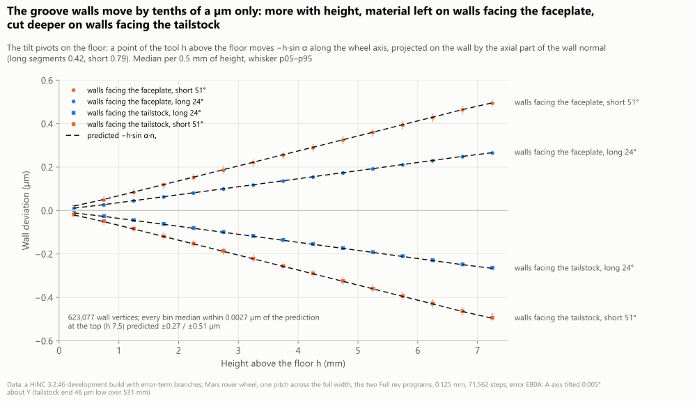
The groove walls' deviation against the height h above the floor: four kinds of wall (facing the faceplate / the tailstock × long 24° / short 51° segments), median per 0.5 mm (whiskers p05–p95) against the prediction −h·sin α·nₓ (dashed). Every bin median lies within 0.0027 µm of the prediction. Symmetric ±0.6 µm axis, a HiNC 3.2.46 development build with error-term branches.
The walls are the vertices at 242.6 ≤ r ≤ 249.9 lying 1.9–2.2 mm from a grouser's centre line, 623,077 of them, with h = r − 242.5. Each wall's prediction is −h·sin α·nₓ, where nₓ is the axial component of the wall's normal pointing into the groove, computed from the design geometry at each wall vertex's radius (the design values 0.414 / 0.781 hold at R 242.5; the ±0.419 / ±0.786 in the table are each wall's median); the predictions in the table use it vertex by vertex:
| Wall | Facing (normal nₓ) | Vertices | Median, top 0.5 mm | Predicted (h 7.25) | Slope ÷ predicted | Bin medians from the prediction |
|---|---|---|---|---|---|---|
| Long 24.4°, lower grouser | the faceplate (−0.419) | 228,828 | +0.2647 µm | +0.2664 µm | 0.987 | ≤ 0.0019 µm |
| Short 51.3°, upper grouser | the faceplate (−0.786) | 84,701 | +0.4942 µm | +0.4961 µm | 0.988 | ≤ 0.0027 µm |
| Long 24.4°, upper grouser | the tailstock (+0.419) | 226,844 | −0.2640 µm | −0.2664 µm | 0.996 | ≤ 0.0024 µm |
| Short 51.3°, lower grouser | the tailstock (+0.786) | 82,704 | −0.4938 µm | −0.4962 µm | 0.997 | ≤ 0.0026 µm |
- All wall vertices: p01 / p99 −0.470 / +0.470 µm, |d| p99 0.489 µm, largest search value 2.64 µm (13 vertices above 0.6 µm, not rechecked).
- How to read it: relative to the wheel, the tool at the height h above the floor sits h·sin α toward the faceplate. A wall facing the tailstock stands on the faceplate side of the groove, and the tool moves into it, so it is cut deeper; from a wall facing the faceplate the tool moves away, so it keeps material. The radial part of the offset lies in the wall's plane and only slides along it, so it does not move the wall.
- The R5 round corners at the chevron bends (14,704 vertices): p01 / p99 −0.434 / +0.455 µm, largest search value 0.771 µm (not rechecked), the same size as the walls.
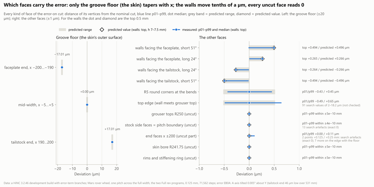
The deviation of each kind of face, measured (blue: p01–p99 and median) against predicted (grey band, diamond). Three floor sections (the faceplate end −17.01, the middle 0, the tailstock end +17.01 µm) on a ±20 µm axis; the walls, R5 round corners, wall top edge, grouser tops, stock side faces, end faces, bore, rims and ring on a ±1 µm axis. The grouser tops, stock side faces, bore, rims and ring lie within ±5×10⁻¹⁰ mm (p01–p99); the end faces reach p99 +0.11 µm (the edge of a grouser's end face next to a wall moves with the wall). 0.125 mm grid, a HiNC 3.2.46 development build with error-term branches.
| Face (how it is picked) | Vertices | p01 (µm) | Median (µm) | p99 (µm) | Largest |d| (search value; those above 20 µm rechecked exactly) | Predicted (µm) |
|---|---|---|---|---|---|---|
| Groove floor (242.4–242.6, at least 1.5 mm from a wall) | 1,505,688 | −17.106 | +0.03 | +17.111 | 17.548 µm (not rechecked) | x·sin α |
| Floor–wall corner strip (floor band, 1.8–2.6 mm from the centre line) | 44,959 | −17.332 | 0 | +16.981 | 83.734 µm (rechecked: a real difference) | x·sin α (dilemma 8) |
| Walls | 623,077 | −0.470 | 0 | +0.470 | 2.640 µm (not rechecked) | ≤ 0.51 |
| R5 round corners at the chevron bends | 14,704 | −0.434 | 0 | +0.455 | 0.771 µm (not rechecked) | ≤ 0.51 |
| Wall top edge (where a wall meets a grouser top) | 23,269 | −0.490 | 0 | +0.646 | 18.115 µm (not rechecked) | ≤ 0.51 (a sharp edge) |
| Grouser tops (R 250, uncut) | 122,093 | −4.8×10⁻⁷ | 0 | +4.8×10⁻⁷ | 5×10⁻⁷ µm | 0 |
| Stock side faces (the pitch boundaries, uncut) | 433,777 | −4.4×10⁻⁷ | 0 | +4.4×10⁻⁷ | 178.7 µm (13 artefacts, the same vertices and values as in the control, all exactly 0; 10 of them also in the marked run's recheck) | 0 |
| End faces x ±200 (away from the groove's edge) | 8,204 | 0 | 0 | +0.11 | 250 µm (2 artefacts, exactly 0; the rest ≤ 0.31 µm) | 0 |
| Edge where the floor meets an end face | 2,402 | 0 | 0 | +17.466 | 125 µm (7 artefacts, exactly 0; the rest at most 18.324 µm, not rechecked) | 0…17.45 |
| Bore R 241.75 (uncut) | 1,432,132 | −4.9×10⁻⁷ | 0 | +4.9×10⁻⁷ | 5.0001×10⁻⁷ µm | 0 |
| Rims and stiffening ring (uncut) | 58,011 | −4.8×10⁻⁷ | 0 | +4.8×10⁻⁷ | 5×10⁻⁷ µm | 0 |
The geometric bound. At every step the marked run only puts the same tool at a pose offset by δ (≤ 17.98 µm) and turned by 0.005°, so the surface it cuts, the boundary of the union of those tool volumes, can lie no further from the nominal cut than 17.98 µm + √(6² + 7.5²) mm × sin α = 18.82 µm. That takes the cutting point farthest from the tip, the Ø12 tool's bottom edge 6 mm out at the groove's 7.5 mm depth, a lever of 9.60 mm that adds 0.84 µm for the turn; it is a conservative bound. Of the 4,313,736 vertices, the search reads 308 beyond it:
- 288 in the corner strip: the 265 beyond 20 µm, rechecked exactly, are real differences between the two exported meshes (−83.74…+20.10 µm, 264 of them at x < 0); the other 23, at 18.82–20 µm, are search values, not rechecked, and may be smaller.
- 11 on the stock's side faces: 10 exactly 0; the eleventh (+19.04 µm) lies below the marked run's recheck threshold, and the same vertex rechecks as 0 in the control.
- 9 at x = −200 (2 on the end face, 7 on its edge with the floor), exactly 0.
- None on any other face.
The corner strip's 265 exceed the bound: the measurement and the reasoning disagree, and that is recorded as a finding (probably the 0.125 mm grid extracting the concave corner differently, dilemma 8). Those on the stock's side faces and at x = −200 are artefacts of the distance search (dilemma 7).
Vertices the search reads beyond 0.020 mm, more than the largest predicted 17.45 µm: 284, a share of 6.6×10⁻⁵. Rechecked exactly, 265 are real (all in the corner strip) and 19 are artefacts of the search (10 on the stock's side faces, 9 at x = −200).
The controller that knows the error (mark cleared, trimmed)
This run clears EB0A's mark, keeps the switch on and keeps G54. The machine is still the one whose A axis
is tilted 0.005°, and now the controller's model holds the tilt too. But the programs are G43 H
four-axis positioning programs: the machine coordinates come from the program words, G54 and the tool
length alone, and the controller never looks at the machine chain. So it has nothing to correct.
- Machine coordinates: X, Z and A differ from the nominal run's by exactly 0 at every step, bit for bit as in the marked run.
- Tool tip: bit-identical to the marked run, off by x·sin α as before.
- Part: the eight
Diff--Statsnumbers are the same, and the coordinates and distances of the 3,139,116 vertices of the exported cut are bit-identical.
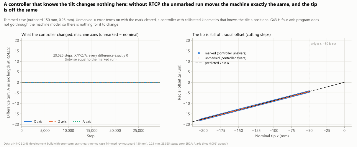
The run with the mark cleared, in the trimmed case (the outboard 150 mm, 0.25 mm, 29,525 steps). Left: the per-step difference of the machine axes from the nominal run (X, Z, and A as arc length at R 242.5) is exactly 0 everywhere, bit-identical to the marked run. Right: the radial tip offset, marked (blue) and mark cleared (orange), on top of each other on x·sin α. Symmetric ±20 µm axes, a HiNC 3.2.46 development build with error-term branches.
This is the opposite of the forged wheel and the
NIST frustum, whose programs use G43.4 (RTCP): there,
clearing the mark gives a calibrated controller, and the part comes back to the nominal one. Here, a
calibrated controller helps only once the program is rewritten for RTCP and run on a controller that
knows the tilt (what a mark changes); otherwise the
remedy is mechanical: a test bar between the two centres, indicated along X, and the tailstock shimmed.
The whole groove was not played with the mark cleared, since it must equal the marked run, and there is no capture of such a run, so this page has no “controller unaware / aware” alternation; the chart above shows the comparison.
The control run and the Diff on the part
The control run (switch off, with a Diff) is the nominal run played again: its tool tips, machine
coordinates and IsTouched equal the nominal run's on all 71,562 steps, bit for bit. Its exported cut,
4,316,019 vertices, lies p01 / p99 ±4.8×10⁻¹⁰ mm from the nominal cut. The 15 vertices the search reads
beyond 1×10⁻⁶ mm all lie on the stock's side faces (−0.179…+0.081 mm), and rechecked exactly against the
nominal cut they are all 0. With the exact values, every vertex lies within −8.62×10⁻⁷…+9.31×10⁻⁷ mm, and
100 % within 0.5 µm. That is the noise floor: the error's effect (±17 µm) is more than seven orders of
magnitude above its p01 / p99, and four above the largest exact value.
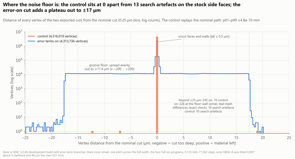
The distance of every vertex of the two exported cuts from the nominal cut (0.25 µm bins, log counts; the search values are plotted, not replaced by the exact ones). The control (orange) sits at 0 apart from 13 search artefacts on the stock's side faces: three single-count bars within ±25 µm, at −12.17, −6.95 and +19.04 µm, and 10 vertices beyond ±25 µm, all exactly 0 against the nominal cut. The error-on cut (blue) adds a plateau out to ±17.4 µm (the groove floor) besides the walls and uncut faces near 0. Beyond ±25 µm: 245 vertices of the error-on cut, 226 of them in the floor–wall corner strip, real differences between the two exported meshes confirmed by the exact check (dilemma 8), and 19 search artefacts; the control's 10 are search artefacts. 0.125 mm grid, a HiNC 3.2.46 development build with error-term branches.
The three pictures below alternate in place, at one camera, between the run with the error terms on (marked) and the control run (off).
- They were taken by putting each run's recorded stock back on the canvas with its Diff, not by playing the run again.
- The canvas carries no interface text, so the English and Chinese canvas captures are identical pixel for pixel; only the frame labels follow the language.
- The cameras are HiNC's default top and isometric views, zoomed with the mouse wheel. The top view is this case's comparison picture.
The whole chevron groove from straight above (the 400 mm width across the picture: left = the faceplate end, x −200; right = the tailstock end, x +200), alternating in place between error terms on (marked) and off (control). With the error terms on, the floor runs from orange-red at the left end (about −17 µm, cut too deep) through green at mid-width to blue at the right end (about +17 µm, material left), the colour bands square to the wheel's axis, the walls and grouser tops green; with them off the groove is green throughout. Read off the Df colour bar along the floor: −0.015 mm at the left end, 0.000 in the middle, +0.017 mm at the right end. The whitish spots on the floor, clearest low on the right, are highlights of the canvas lighting, in the same place in the “off” frame too, not a deviation. Diff colour range ±0.02 mm (red = cut too deep, blue = material left, green = 0, both signs weighted alike); 0.125 mm grid; a HiNC 3.2.46 development build with error-term branches.
A close-up from above of the floor at mid-width (scale bar 9.67 mm), alternating in place between on and off. With the error terms on, the left side (x < 0) leans yellow-green, the right side (x > 0) cyan-green, and the middle, around the touch-off point, is green: the deviation changes sign here. With them off, all green. The second bar at the lower right, “L. 0–1”, is HiNC's colour bar for colouring by a per-step property, not part of the Diff; the two white spots on the floor are highlights of the lighting (in the same place in the “off” frame). Colour range, grid and build as above.
The whole wheel seen obliquely, looking in from the outboard end, x −200, with the hub plate and the Ø80 mandrel in front; alternating in place between on and off. With the error terms on, the floor of the pitch that was cut runs from red-orange at the near (faceplate) end through green to blue-green at the far (tailstock) end; the other 26 grooves are fixture (grey). With them off, all green. Colour range, grid and build as above.
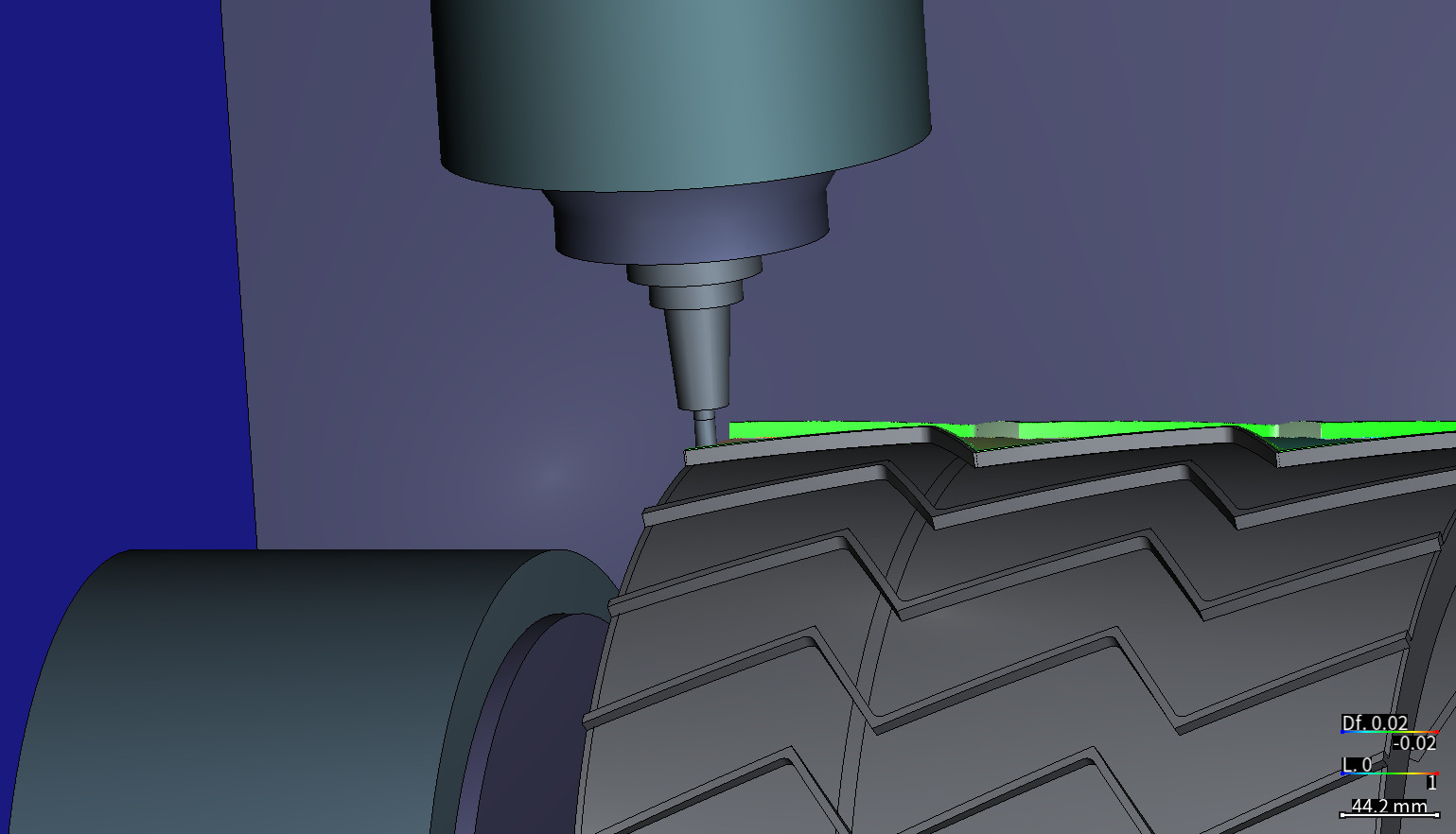
The pose of the picture at the top of the page, closer: the tapered nose of the shrink-fit holder, the cutter reaching into the outboard end of the groove onto the floor at X −201, and the rotary table's faceplate on the left. None of the runs reported a collision. The “L.” bar at the lower right is not part of the Diff. Diff colour range ±0.02 mm, a HiNC 3.2.46 development build with error-term branches.
Diff--Stats of the five runs with a Diff
| Run | Reported leaves | Surface leaves before comparison | Expanded on demand | New nodes | NaN leaves | Measured wires | Unmeasured wires | Target triangles |
|---|---|---|---|---|---|---|---|---|
| f-on | 4,651,503 | 4,063,212 | 229,740 | 818,031 | 127 | 18,441,099 | 8,182 | 8,141,641 |
| f-control | 4,654,293 | 4,071,640 | 224,335 | 806,988 | 21 | 18,437,350 | 5,564 | 8,141,641 |
| t-on | 3,669,790 | 2,800,958 | 327,853 | 1,196,685 | 26 | 14,548,922 | 7,440 | 5,604,930 |
| t-unmarked | 3,669,790 | 2,800,958 | 327,853 | 1,196,685 | 26 | 14,548,922 | 7,440 | 5,604,930 |
| t-control | 3,671,704 | 2,802,665 | 328,125 | 1,197,164 | 16 | 14,547,050 | 5,464 | 5,604,930 |
The nominal runs make no Diff. The trimmed runs compare with the trimmed nominal cut, which is why their target triangle count differs. The share of NaN leaves is at most 2.73×10⁻⁵ (f-on).
What the runs cost
All runs used a private instance of a HiNC 3.2.46 development build with error-term branches on a shared 32-thread server, restarted before every run. VmHWM is the process's high-water mark of resident memory, recorded in bytes; GB = 10⁹ bytes, GiB = 2³⁰ bytes.
| Run | Grid | Steps | Wall clock | Peak memory, VmHWM (GB) | (GiB) | Diff and export |
|---|---|---|---|---|---|---|
| t-nominal | 0.25 mm | 29,525 | 95.1 s | 7.65 | 7.13 | export |
| t-control | 0.25 mm | 29,525 | 125.2 s | 10.34 | 9.63 | Diff, stock recorded |
| t-unmarked | 0.25 mm | 29,525 | 135.1 s | 12.38 | 11.53 | Diff, export, stock recorded |
| t-on | 0.25 mm | 29,525 | 135.2 s | 12.85 | 11.96 | Diff, export, stock recorded |
| f-nominal | 0.125 mm | 71,562 | 605.6 s | 11.13 | 10.36 | export |
| f-on | 0.125 mm | 71,562 | 755.9 s | 17.06 | 15.89 | Diff, export, stock recorded |
| f-control | 0.125 mm | 71,562 | 575.6 s | 16.86 | 15.71 | Diff, export, stock recorded |
- Against the plan's estimate. The plan estimated 10–15 minutes and 15–22 GB per whole-groove run; the runs took 9.6–12.6 minutes and 11.13–17.06 GB. The control run's 9.6 minutes is slightly under the time estimate and the nominal run's 11.13 GB under the memory estimate; the rest lie inside. The 40 GB fallback was never reached.
- What the Diff costs. Comparing with the nominal cut's 8.14 million triangles and recording the stock, the marked run peaked 5.93 GB above the nominal run, the control 5.74 GB.
- The wall clock runs from the start of the play to
Finished, with the export, the Diff and the stock record, and may include other load on the server at the time. - In all, the seven runs took 2,427.7 s, about 40 minutes, the three whole-groove runs 1,937.1 s, about 32 minutes, and the build 11 s. The times: the trimmed runs 21:57–22:06 on 2026-10-06, the whole-groove nominal and marked runs 22:07–22:30, the control 02:37–02:47 on 2026-10-07.
- Not comparable with the base case's cost: its acceptance ran with physics on and a Diff against the design model.
What it brings
- For a machining engineer.
- The line through the two centres off the X travel by only 0.005°, 46 µm over 531 mm, takes the 0.75 mm skin from 0.733 mm at the faceplate end to 0.767 mm at the tailstock end, 35 µm apart, while the program, the machine coordinates and the touch-off all look right. A skin that changes linearly across the width and stays the same round the wheel is this error's fingerprint.
- A touch-off takes out the A axis' position error but not its orientation error, and with a program without RTCP, a controller with calibrated kinematics has nothing to correct. The remedy is aligning the centres mechanically — a test bar between them, indicated along X, the tailstock shimmed — or a program rewritten for RTCP on a controller that knows the tilt.
- The walls move by tenths of a micrometre, in a direction one can predict; the grouser tops, the end faces away from the groove's edge and the bore do not move.
- In HiNC, a constant error measured on a machine can be put into its model, to see its shape and size on one's own part before the part is cut.
- For a teacher or a student.
- How a rotary axis' position error differs from its orientation error: on work whose program zero lies on the axis, the position error goes into the work offset, and the orientation error becomes a taper along the axis.
- How the tip offset δ = R_A⁻¹(R_y(−α) − I)(T − c) splits into a radial x·sin α and an axial −(ρ − z0)·sin α, and why choosing the touch-off point is choosing the pivot.
- A surface keeps only the part of the offset along its normal: the floor all of it, a wall only the axial part times the axial component of its normal, and nothing of what slides along it.
- Marked and unmarked stand for uncalibrated and calibrated kinematics, and that difference exists only under RTCP, a tilted plane or CL playback.
- For someone weighing the approach.
- The build and seven plays took about 40 minutes of server time; a whole-groove run took 9.6–12.6 minutes at a peak memory of at most 17.06 GB.
- The predictions were written before the first play: the tip formula holds on all 71,562 steps within 4.07×10⁻¹³ mm, the floor's 40 bin medians within 0.0183 µm, and the four kinds of wall within 0.0027 µm, down to their 0.27 / 0.51 µm at the top — first-order effects in proportion to α like the floor's, small only because h ≤ 7.5 mm.
- What needed saying is written as measured: criterion 5's filter, the search artefacts in the mesh distance, and the strip at the foot of the walls.
Honest limits
- One error, and a constant one. A real A axis has other errors at the same time: a position error (taken up by the touch-off in this set-up), a tilt in the horizontal plane, EC0A (which would twist the groove's direction), and a radial run-out and wobble that vary with the angle. An error term holds only a constant error; errors that vary with position (positioning, straightness, volumetric error tables), backlash, servo mismatch and thermal growth cannot be expressed (Machine Geometric Error).
- The size and the sign are chosen. 0.005° is a typical value; this generic machine was never measured, and no published figure for it was found. Every deviation is in proportion to α. With the tailstock end high instead, every deviation turns over: material left at the faceplate end, cut too deep at the tailstock end.
- The touch-off is assumed. The pivot at the touch-off point assumes the shop touches off at mid-width (Z on the stock top, X on the outboard end face, Y and Z on the A axis' centre). Finding the A axis' centre at the faceplate end instead adds only a constant shift of (+21.2, 0, −24.4) µm; the taper stays.
- The tailstock body stays at its nominal place. In the model the faceplate, the fixture and the wheel tilt, while the tailstock body hangs on the X anchor and does not move. For the cut this is the same as the line through the two centres tilted, and the pictures should be read that way.
- Geometry only. Physics is off: no cutting force, no deflection, no heat. The base case recorded the force along the tool axis that pulls the skin outward, a median of 183 N in roughing; the deflection it causes was never part of the removal geometry.
- One pitch only. The other 26 grooves are fixture. The taper is linear across the width and the same round the wheel, so every groove of the whole wheel would carry the same.
- Reading a 0.125 mm mesh.
- The 265 vertices of the floor–wall corner strip (down to −84 µm) are real differences between the two exported meshes, probably the grid's extraction of the concave corner (not verified directly, dilemma 8); the floor statistics keep 1.5 mm away from it.
- The 39 vertices on one grid line of the floor (search values up to 7.6 µm above the prediction, not rechecked) stay in the floor statistics: they are the fit residual's largest value, 7.6 µm, but they are 2.6×10⁻⁵ of the floor's vertices, and the p95 / p99 and the bin medians hardly change.
- The 91 vertices of the wall top edge (search values up to +18.2 µm, not rechecked) are not in the walls' statistics, which take r ≤ 249.9.
- What was rechecked exactly. The exact point-to-triangle distance against the nominal cut was computed only for the vertices the search read beyond a threshold: 0.02 mm for the whole groove's marked run, 1×10⁻⁶ mm for its control, 0.02 mm for the trimmed marked and mark-cleared runs. Extremes below it remain search values, an upper bound on |d|.
- The Diff's target has fewer triangles than the STL. HiNC reports 8,141,641 target triangles for the nominal cut, while reading the same STL offline gives 8,143,292 faces (1,651 fewer); trimmed, 5,604,930 against 5,605,332 (402 fewer). Degenerate triangles may be dropped; this was not looked into, and no conclusion depends on it.
- The removed volume was not measured. The predicted ±103.8 mm³ of the two halves cancel; the records hold no removal series.
- The records hold warnings and above only; messages below that level were not kept.
- The wall clocks include the export, the Diff, the stock record and the server's other load at the time.
What a reader can take to their own case
- Ask what a touch-off takes out before choosing an error. On work whose program zero lies on a rotary axis, the axis' position errors vanish into the work offset; its orientation errors stay and show as a taper along the axis.
- Put the pivot at the touch-off point. Then the work offset a touch-off finds does not move, and no run needs a typed offset; say which touch-off the pivot assumes.
- Without RTCP, a tilted plane or CL playback, marking does not matter, even with a rotary axis in the program: the controller does not read the chain, and only mechanical alignment, or an RTCP program on a controller that knows the error, takes it out (what a mark changes).
- Read a thin floor as a thickness against x. An A axis tilted against the X travel tapers it linearly across the width and leaves it the same round the wheel.
- Judge a criterion as written. A filter that takes in uncut faces fails a correct result; the selection that was meant is a finding about the plan, never a new verdict.
- Check extreme mesh distances exactly before reading them as shape, and expect a concave corner to differ between two exported meshes by up to half a cell's diagonal.
- Take the cutting steps from one run's touch flag. A grazing step can touch in one run and not in the other, and “where the largest offset is” can move with it.
- Prove the per-step formula on a coarse trimmed run, and keep the fine grid for the part and the pictures.
Source and licence
- Wheel numbers: Rankin, A. et al., Assessing Mars Curiosity Rover Wheel Damage, IEEE Aerospace Conference 2022, Jet Propulsion Laboratory, https://www-robotics.jpl.nasa.gov/media/documents/fmwi-rankin-2022-0225-final.pdf. © 2022 IEEE; only facts (numbers) are used: diameter 50.0 cm including the grousers, width 40.0 cm, skin 0.75 mm, 19 chevron grousers plus 8 straight ones, four chevron features each, a rim on each edge and a stiffening ring. Search: Rankin 2022 Mars rover wheel wear.
- Lakdawalla, E., Curiosity wheel damage: The problem and solutions, The Planetary Society, 2014-08-19, https://www.planetary.org/articles/08190630-curiosity-wheel-damage. Only facts are used: grousers 7.5 mm high and 15° apart, each tire machined from one block of aluminium.
- NASA Science, Curiosity's and Perseverance's Wheels, https://science.nasa.gov/resource/curiositys-and-perseverances-wheels/, credit NASA/JPL-Caltech. Its illustration served the base case as an internal shape reference only and is not reproduced: NASA's media guidelines keep imagery out of the public domain and limit commercial use to non-promotional editorial use. Photographs of the real wheels are on NASA's page. Search: Curiosity's and Perseverance's Wheels.
- Licence: the facts (numbers) are free to use. No NASA image is reproduced, no NASA endorsement is suggested and no NASA logo is used.
- Attribution: “Wheel numbers: NASA/JPL-Caltech, The Planetary Society. Rebuilt for machining simulation by Tech Coordinate's agent; not a NASA or JPL design file and not endorsed by NASA.” The published numbers are taken as they stand, without warranty.
- What was used and changed:
- The wheel model, the stock, the fixture, the machine, the spindle, the tools and the programs are the base case agent's, built from those numbers, as the wheel's case page tells; the chevron shape, the grouser thickness and the rim and ring sizes are estimated from a photograph. None of it is a NASA or JPL design file.
- The kind of error, its size, its sign, its pivot and the touch-off it assumes are the agent's choices. EB0A is the name ISO 230-7 gives this error; the value is not a measurement of any machine.
- No third-party picture is reproduced. The pictures are HiNC captures, the charts are drawn from HiNC's per-step results and exported cut meshes, and the side-view schematic is our own drawing.
- No source file was taken, and this site offers no download.
- Everything on this page is simulated; no wheel was cut.
See Also
- Mars Rover Wheel: A 0.75 mm Skin between Chevron Grousers, Milled on Four Axes — how the wheel, its machine and the programs cut here were built and accepted
- Building Virtual Machine Tools: Error terms — where an error term may go, what a mark changes, the switch, and work offsets on a machine with error terms
- Kinematic Topology: Error-Term Branches — the nominal chain the controller solves, and which errors it can see
- Machining Issues Outside the Model: Machine Geometric Error — the machine errors an error term cannot hold
- A 17-Inch Forged Aluminium Wheel on a C Table 20 µm Off Centre — a rotary axis' location error under
G43.4, where a calibrated controller cuts the nominal wheel - The NIST Cone Frustum on a C Axis 10 µm Off Centre — the same kind of error under RTCP on a table-table machine
- Geometry Validation — the geometry difference, its detection radius and its colour scale
- Mesh Resolution — choosing the grid against the thinnest wall
- Program Zero Alignment — P0, and typing in a measured work offset
- Showcase — the other cases, and how a case page reads