Mars Rover Wheel: A 0.75 mm Skin between Chevron Grousers, Milled on Four Axes
Curiosity's wheels were each machined from one block of aluminium: 500 mm across the treads, 400 mm wide, and between its chevron treads (grousers) a skin of 0.75 mm, which JPL calls “the absolute minimum thickness that was machinable”. No licence-clean CAD model of the wheel exists, so an AI agent rebuilt it from published numbers, wrote a four-axis (A-axis) program for one tread pitch across the full width, and played it in HiNC through the web API. The questions were the ones a shop would ask before cutting: does the last 0.75 mm of skin survive, does the holder clear the wheel's edges and the mounting, and do the spindle and the tools stay within their limits. HiNC answered the third one with a no, pointed at where, and the revised program passed.
Everything here is simulated: no wheel was cut on a real machine. The wheel on this page is the agent's own model, not a NASA or JPL design file; photographs of the real wheels are on NASA's page. Each dilemma below gives the risk, how it came to light, the resolution and the evidence that it held. The built project was the agent's working material and is not distributed.
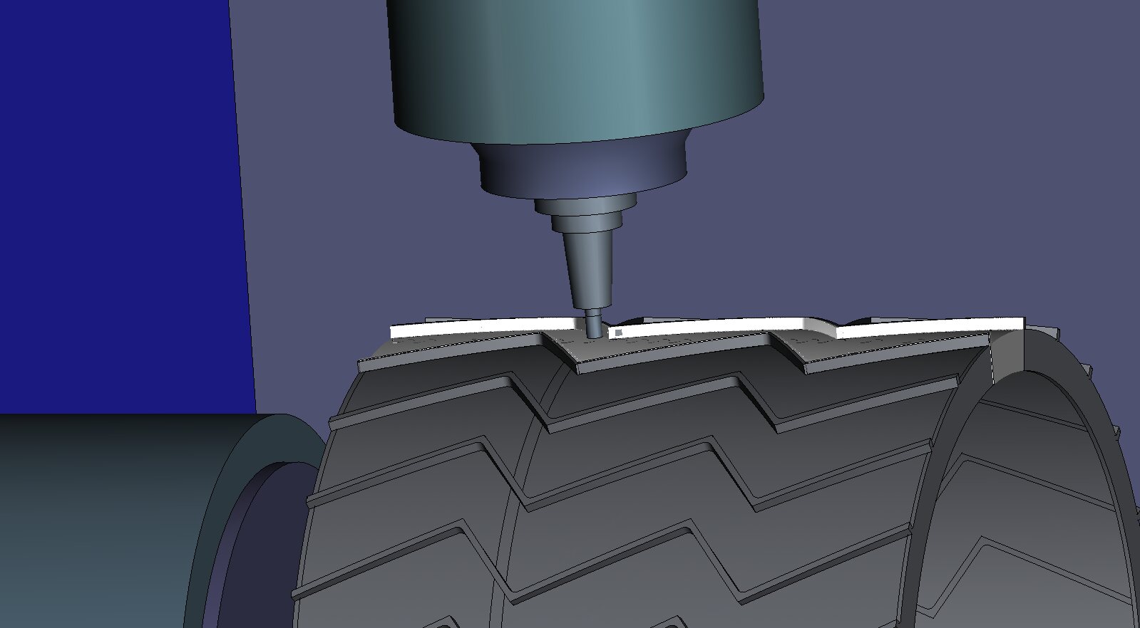
The agent's wheel model on HiNC's canvas: the Ø10 end mill, 20 mm out of its shrink-fit chuck, stands at the floor of the groove this case cuts (the lighter pitch at the top); the other 26 grooves are drawn as part of the fixture. Captured on HiNC 3.2.42 after replaying the finished pitch from its record.
The case
Three public sources give the wheel's numbers; none gives a model or a drawing to machine from:
- Rankin et al., JPL, IEEE Aerospace Conference 2022, Table 1: diameter including grousers 50.0 cm, width 40.0 cm, skin 0.75 mm, “19 chevroned grousers plus 8 straight grousers”; the text adds “a vertical rim on each edge of the wheel and a stiffening ring around the interior of the wheel, located two-thirds of the wheel width from the inside edge”, and that each grouser “contains four chevron features”.
- The Planetary Society (2014): grousers “protude 7.5 millimeters from the wheel skin”, “spaced 15 degrees apart”; “Each wheel tire was machined from a single block of aluminum”; “a slight crown to the wheel”.
- NASA Science's wheel comparison: 20 inches (50.8 cm) and an illustration, used by the agent only as an internal reference for the shape.
Left out: the chevron shape in numbers, the grouser thickness, the rim and ring sizes, the layout of the odometry section, the alloy (“flight-grade aluminum”), the order of the turning and the milling, the machine, the fixture, the tools and the program.
What the agent built
Everything went through HiNC's web API, following Project Construction, Driving the Web Service over HTTP and Replay Acceptance over the HTTP API. Each value is marked read (stated by a source), derived, chosen (by the agent where the sources are silent), estimated (from a photograph) or measured (in a run on a HiNC build of 2026-10-01).
| Item | Value | Basis |
|---|---|---|
| Wheel | Ø500.0 over the grousers, 400 wide, skin 0.75, grousers 7.5 high | Read (JPL's 50.0 cm “including grouser”; NASA's rounded 20 in not used) |
| Tread | 19 chevron grousers 15° apart, each zig-zagging across the width with four bends; 8 straight grousers 10° apart fill the remaining 90° | Counts and spacing read; bend positions (x = −95, −55, 55, 95 mm), slopes (24° and 51°), 4 mm thickness (about a sixteenth of the pitch on the photograph) and the straight grousers' positions estimated |
| Inside | a 3 mm rim 25 mm deep on each edge, an 8 mm ring 20 mm deep a third of the width from the outboard edge; the tread a plain cylinder (the crown is not quantified anywhere) | Positions read, sizes estimated |
| Material | AA7075 | Chosen: the alloy is not published; 7075 is a second-hand claim |
| Block for the whole wheel | Ø500 × 400; 98.4 % of it is cut away to leave the wheel | Derived (from the model) |
| Stock | one tread pitch across the full width, between two grousers' centre lines, its inside already turned: 231.1 cm³ | Chosen |
| Design model | the same pitch with its groove milled to the 0.75 mm skin; walls as a Ø10 cutter kept on a wheel radius leaves them, inner corners R5; 178.3 cm³ removed | Derived |
| Fixture | the rest of the finished wheel, a Ø80 mandrel between the rotary table and the tailstock centre, a hub plate on the stiffening ring | Chosen |
| Machine | generic vertical four-axis machine: X-Y-Z, an A table along X, a tailstock; the A axis 330 mm above the table | Chosen, generated from boxes and cylinders |
| Program zero | on the A axis at mid-width; G54 (0, 0, −670) | Chosen; G54 measured |
| Controller, spindle | Fanuc; the Showcase's generic spindle, 7.5 kW continuous, 10 kW short term | Chosen |
| T1 roughing | Ø12 three-flute aluminium end mill, 16 mm flute, 25 mm out of a shrink-fit chuck, 12,000 rpm, 2,880 mm/min (0.08 mm per tooth) | Chosen |
| T2 finishing | Ø10 three-flute, 14 mm flute, 20 mm out, 14,000 rpm, 2,100 mm/min (0.05 mm per tooth) | Chosen |
| Holder | shrink-fit chuck, Ø24 nose, 4.5° taper, 80 mm gauge length | Chosen: the usual proportions of DIN 69882-8 |
| Cutting edge | hone radius 5 µm (a ground edge for aluminium), relief angle 10° | Chosen |
| Program | roughing in two levels (R 246.5, then R 243.0, leaving 0.5 mm on the floor and 0.3 mm on the walls): passes round the wheel at fixed X, 6 mm steps along the walls, then one climb pass round the walls; finishing the floor at R 242.5 in 7 mm steps, then the walls at full height | Chosen |
| Resolution | 1 and 0.25 mm on a trimmed program, 0.125 mm for acceptance | Chosen (Mesh Resolution) |
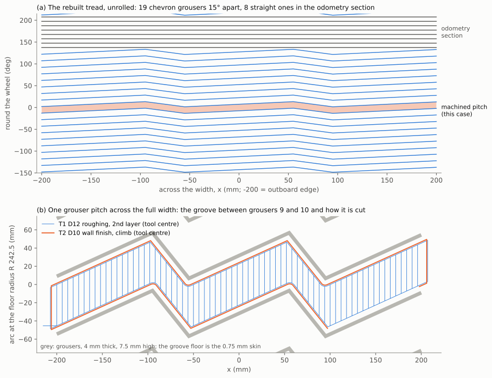
Above, the whole tread unrolled with the machined pitch shaded; below, that pitch between grousers 9 and 10, with the tool centre of the second roughing level (blue) and of the climb wall finish (orange).
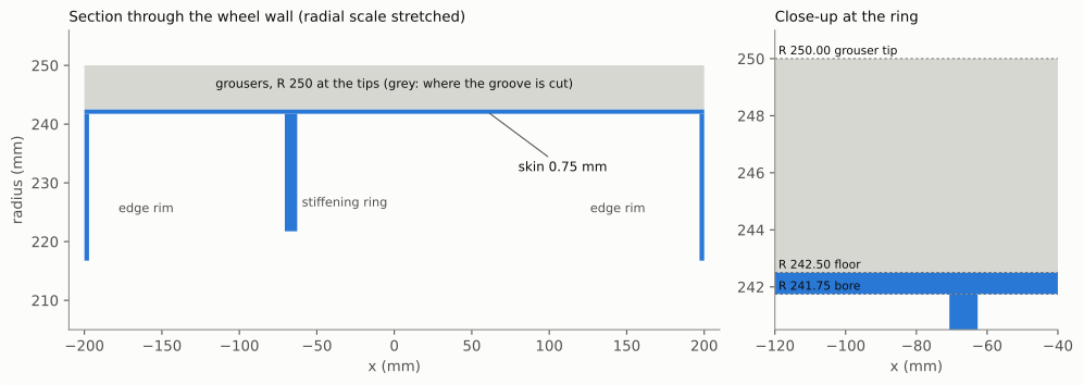
The wall in section: the rims and the ring run inward from the skin, so the grooves are open at both edges.
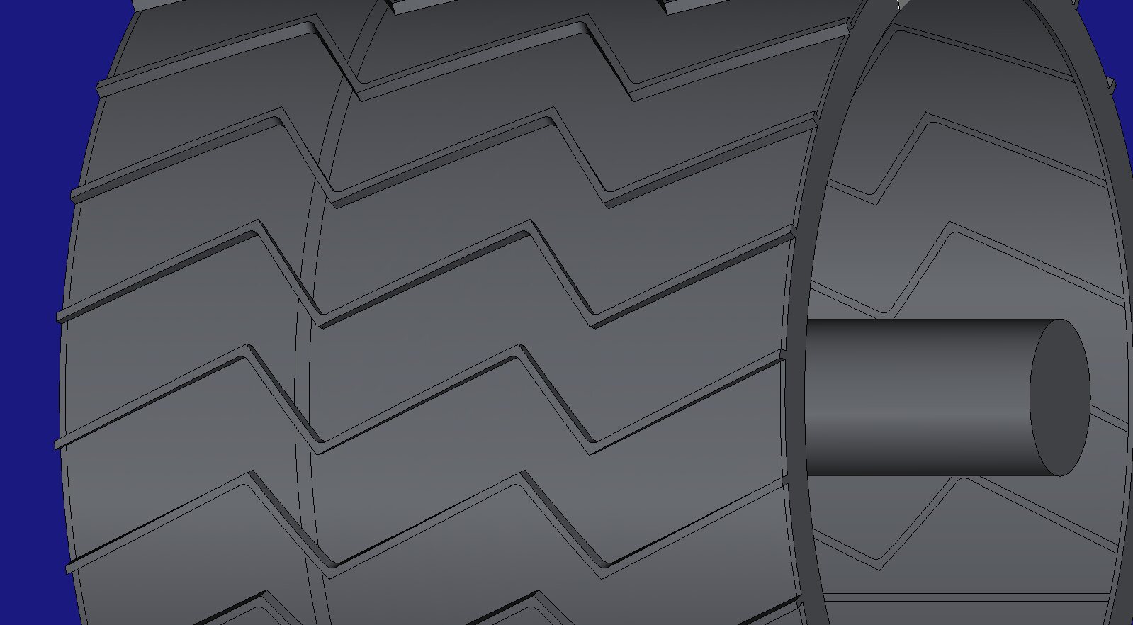
The wheel model in HiNC, the machine hidden. The fine line round the tread is the stiffening ring's edge showing through the 0.75 mm skin in the rendering, in the right place; inside the wheel the grousers' outlines show through the same way.
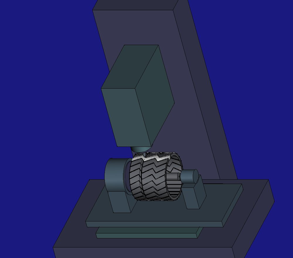
The four-axis machine the agent generated from boxes and cylinders, the A axis 330 mm above the table.
How the agent managed the work
- Pass criteria before the first play. Six criteria were written into the case's notes and committed before HiNC played anything: the skin not read as a hole, the holder clear of the rims, the neighbouring grousers and the mounting, a clean run, spindle power and torque and the tool's stress below their limits, the removed volume within 5 % of the model's, and the force along the cutter recorded.
- Small before large. A trimmed program (the outboard 150 mm of the groove, the first chevron bend included) ran at 1 mm and 0.25 mm before the full groove; the full groove ran once, at 0.125 mm, queued behind other agents' runs on a shared 32-core server.
- Measured outside HiNC too. The finished part HiNC exports was measured along radial lines by a script of the agent's own, and the holder's clearance to every fixed solid computed from the program.
- Where a person stepped in. HiNC's product owner chose the case among ten product cases, ruled that the public page shows the agent's own model and HiNC's pictures rather than NASA's illustration, and that every tool sits in a realistic holder at the shortest stick-out that is enough.
The dilemmas
Unless a dilemma says otherwise, its numbers were measured on a HiNC build of 2026-10-01; the run times and memory, the 1 mm grid trial and the Al6061-T6 trial come from runs of the same programs on HiNC 3.2.42.
Three diameters for one wheel
- Situation. Curiosity's wheel is 50.0 cm in JPL's paper (“including grouser”) and 20 inches (50.8 cm) in NASA's comparison caption; Perseverance's is given as 52.3, 52.5 and 52.6 cm.
- Risk. A model 8 mm too large, and every radius on this page wrong with it.
- How it was noticed. Collecting the sources before building.
- Resolution. The engineering paper's 50.0 cm, stated to include the grousers; the 20 inches reads as a rounded figure.
- Evidence it held. With the 7.5 mm grousers and the 0.75 mm skin of two independent sources, the model's radii (250, 242.5, 241.75 mm) follow without a further choice.
A tread described in words
- Situation. The sources give counts and spacing (19 chevrons 15° apart, “four chevron features” each, 8 straight grousers) but no shape, thickness or layout.
- Risk. Tracing a drawing, which the illustration's terms do not allow, or a tread that looks nothing like the wheel.
- How it was noticed. The case's own rule: photographs for the shape, no drawing traced.
- Resolution. The agent read the shape off the photograph as numbers — four bends at x = −95, −55, 55 and 95 mm, long segments at 24° and short ones at 51°, 50 mm of arc each way, a 4 mm grouser — and put the 8 straight grousers 10° apart in the remaining 90°, since 19 × 15° leaves exactly that. Each estimate is marked as one.
- Evidence it held. Nineteen chevrons at 15° close the circle with the odometry section at 90°; the unrolled layout shows no grouser crossing another.
The rims face inwards
- Situation. The plan for the case expected a rim standing proud of the tread on each side, for the holder to clear.
- Risk. Checking clearance to a feature the wheel does not have, and missing the ones it has.
- How it was noticed. The photograph shows the grousers' ends as teeth on the wheel's side, which a raised rim would hide; JPL lists the edge rims beside the interior ring as structure.
- Resolution. The rims are walls running inward from the skin, and the grooves are open at both edges. The clearance criterion was written for what is there: the rims, the neighbouring grousers, the mandrel, the rotary table and the tailstock.
- Evidence it held. See the result: the cutter drops to depth 9 mm outside the rim, and the nearest fixed solid, the rotary table's stator ring, stays 87.8 mm from the tool assembly.
Why not three axes
- Situation. One 15° groove is about 59 mm wide round the wheel.
- Risk. Cut with the table indexed and the tool moving flat, the floor is a chord: 1.8 mm higher in the middle than at the sides, 2.4 times the skin. Either the sides keep 1.8 mm of extra metal or the middle breaks through.
- How it was noticed. Before writing the program.
- Resolution. The tool stays on a wheel radius, straight over the A axis: the table turns the wheel under it while X runs along the width. A straight line of the unrolled groove is then a single linear X-A block, and the floor is a true cylinder.
- Evidence it held. The finished part's skin reads 0.750–0.759 mm, the floor at radius 242.500–242.508 mm across the whole floor.
A feed the controller reads another way
- Situation. In G94, Fanuc (and HiNC's controller model) take a block that moves A as a composite distance, √(ΔX² + ΔZ² + ΔA²) with A in degrees, per minute.
- Risk. A pass round the wheel written with the tool-tip feed would run about four times slower than meant at this radius, and every time and chip thickness with it.
- How it was noticed. Reading how HiNC times a block that turns a rotary axis.
- Resolution. Each block's F is the tip feed times its composite distance over its tip arc: a finishing pass round the wheel at 2,100 mm/min is written F496.2.
- Evidence it held. HiNC's actual tip feed reads 2,880 mm/min on the roughing passes, and the simulated times match the programs' own feed times (the roughing 191.3 s against its 189.1 s of feed, the finishing 125.1 s against 122.8 s, the rest being rapids and plunges).
One pitch of a 500 mm wheel
- Situation. The whole wheel at a width fine enough for a 0.75 mm skin is far more mesh than the question needs.
- Risk. A run too large for the server, or a coarse one that cannot see the skin.
- How it was noticed. Planning memory before building (Memory Planning).
- Resolution. The stock is one pitch cut out between two grousers' centre lines; the rest of the finished wheel is drawn as part of the fixture, so the pictures show the whole wheel and HiNC checks the tools against the neighbouring grousers.
- Evidence it held. The acceptance run at 0.125 mm peaked at 23.1 GB, in the comparison and the export of the finished part; about 17 GB while cutting.
Walls a radial cutter really leaves
- Situation. A cutter kept on a wheel radius leaves walls parallel to its own axis, not radial planes: with a Ø10 cutter the two differ by 0.15 mm over the 7.5 mm grouser height.
- Risk. A design model with radial walls: the comparison would paint 0.15 mm of leftover along every grouser top.
- How it was noticed. Working out the design model's walls.
- Resolution. The design's groove is the cutter itself swept over its axis region, cut at the floor radius.
- Evidence it held. At 0.125 mm the comparison reads the grouser walls within ±0.1 mm like the floor, with no band of leftover along the grouser tops.
A grid coarser than the skin
- Situation. The skin is 0.75 mm; HiNC's workpiece is a grid of cubes.
- Risk. A resolution coarser than the skin reads it as holes: a false “the program cuts through”, or a habit of ignoring the comparison.
- How it was noticed. On the trimmed program, measuring the finished part HiNC exports along radial lines: at 1 mm, 18 % of the lines found no skin at all, and the thinnest read 0.04 mm; at 0.25 mm every line found it, 0.750 to 0.767 mm.
- Resolution. The acceptance ran at 0.125 mm, six cubes through the skin.
- Evidence it held. At 0.125 mm the comparison reads the whole floor within ±0.1 mm with no over-cut, and of 5,344 radial lines through the exported part none found a hole; the 5,229 that met the skin read 0.750–0.759 mm.
The roughing over the spindle's limit
- Situation. With HiNC's shipped AA7075 cutting data, the roughing's spindle power ratio (input power over the spindle's short-term rating) peaked at 1.12 on the trimmed program.
- Risk. A spindle overload on the machine, or a roughing slowed everywhere to fix a few spots.
- How it was noticed. The ratio chart; the agent then read back which program blocks the steps over 1 belonged to. It first blamed only the 6 mm step-overs along the walls, but a revision slowing just those left the peak where it was: the rest were the entry from the open edge, and the ends of the passes on the steep chevron segments, where the walls shift 7.5 mm round the wheel for every 6 mm step and the cutter runs past the previous pass into a full slot.
- Resolution. Those three kinds of move at 60 % feed; everything else unchanged.
- Evidence it held. On the whole groove at 0.125 mm the peak fell from 1.08 to 0.84, for 5.3 % more time: 333.3 s against 316.5 s.
The skin is pulled, not pressed
- Situation. The case set out to show the force pressing on the last 0.75 mm.
- Risk. Reading the sign of the axial force the wrong way round.
- How it was noticed. HiNC's average force on the tool along its axis is negative in its tool frame, whose +Z points up the tool.
- Resolution. The cutter is pulled into the part, so the skin is pulled outwards, as a right-hand helix does: a median of 183 N in the roughing and 24 N in the floor finish.
- Evidence it held. The sign is the same on every roughing and finishing segment.
Results and benefits
The acceptance ran both programs over the whole groove at 0.125 mm, queued on a 32-core server shared with other agents: the as-planned roughing and finishing, then the revision with the full-slot moves slowed. The cutting numbers below are from both programs played again on a HiNC build of 2026-10-01; run time and memory are the acceptance runs' on HiNC 3.2.42.
| Criterion (written before the first play) | As planned | Revised |
|---|---|---|
| The skin not read as a hole | passed: the comparison reads the floor within ±0.1 mm; 0 holes in 5,344 radial lines, skin 0.750–0.759 mm | passed (same finish) |
| The holder clears the rims, the neighbouring grousers and the mounting | passed: no collision message; holder nose at least 12.5 mm over the grouser tips, tool assembly at least 87.8 mm from the rotary table | passed |
| A clean run | passed: every line of both programs; only progress messages and the comparison's counters | passed |
| Spindle power, torque and tool stress below their limits | failed: power ratio 1.08; torque 0.45, stress 0.34 at most | passed: 0.84; torque 0.45, stress 0.34 at most |
| Removal within 5 % of the model, time recorded | passed: 175.7 cm³ (−1.5 %), 316.5 s | passed: 175.6 cm³ (−1.5 %), 333.3 s |
| The force along the cutter (recorded) | 183 N median in the roughing, 24 N in the floor finish, pulling the skin outwards | same |
The two programs segment by segment, as median / 99th percentile / highest step; the last column is HiNC's average force on the tool along its axis (median), negative when the cutter is pulled into the part:
| Program · segment | Cutting steps | Spindle power ratio | Cutting force (N) | Stress ratio | Force along the cutter (N) |
|---|---|---|---|---|---|
| As planned, roughing · first level, round the wheel | 14,488 | 0.53 / 1.06 / 1.06 | 834 / 869 / 870 | 0.25 / 0.26 / 0.26 | −183 |
| As planned, roughing · second level, round the wheel | 14,298 | 0.53 / 1.07 / 1.08 | 834 / 869 / 899 | 0.25 / 0.26 / 0.27 | −183 |
| Revised, roughing · first level, round the wheel | 16,229 | 0.53 / 0.71 / 0.79 | 770 / 839 / 864 | 0.23 / 0.25 / 0.26 | −183 |
| Revised, roughing · second level, round the wheel | 16,003 | 0.53 / 0.71 / 0.79 | 770 / 839 / 892 | 0.23 / 0.25 / 0.27 | −183 |
| Roughing along the walls, both programs, each level | 4,037–4,046 | 0.00 / 0.19 / 0.84 | — / 486 / 899 | — / 0.15 / 0.27 | 0 |
| Floor finish | 21,350 | 0.07 / 0.16 / 0.83 | 80 / 171 / 864 | 0.04 / 0.07 / 0.34 | −24 |
| Wall finish | 6,341 | 0.00 / 0.08 / 0.80 | — / 122 / 864 | — / 0.05 / 0.34 | 0 |
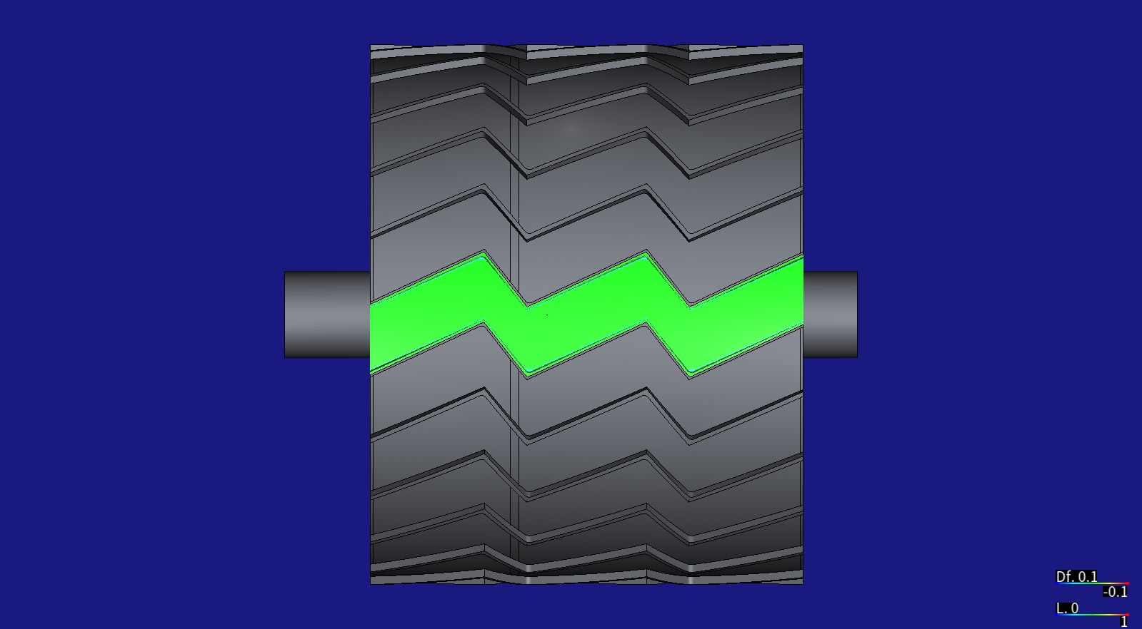
The comparison at 0.125 mm: the whole groove within ±0.1 mm of the design, nothing over-cut.
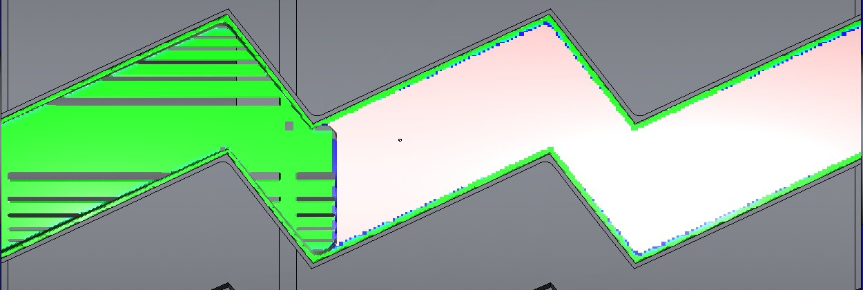
The trimmed program at 1 mm: the grid is coarser than the skin, and the finished floor shows bands where the skin has dropped out of the model.
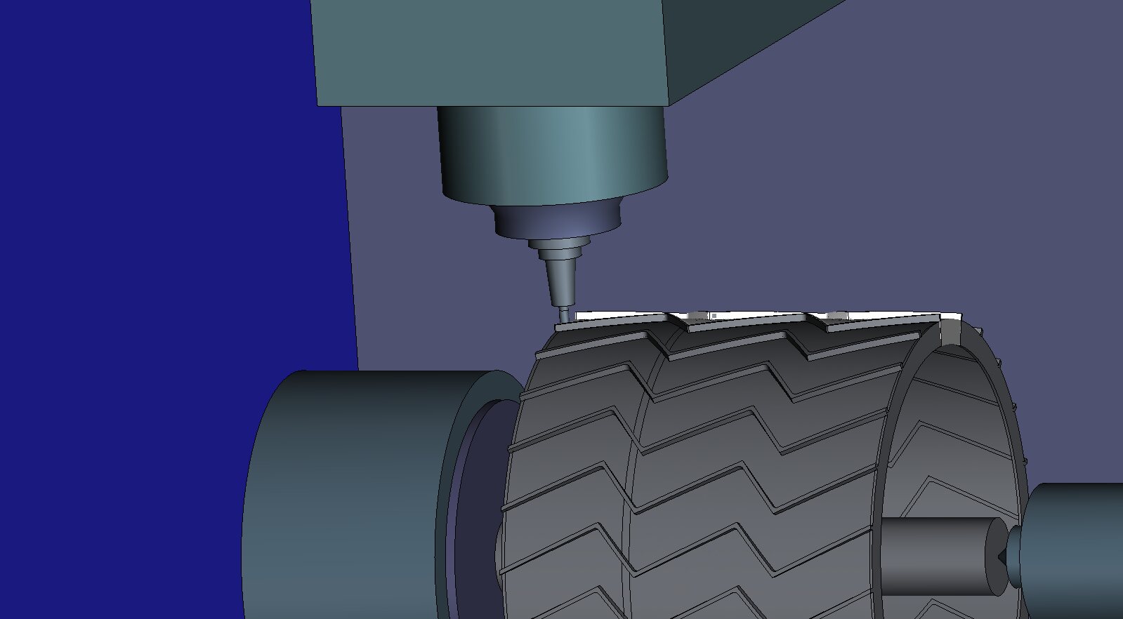
At the outboard rim: the cutter drops to depth in the open, 9 mm outside the rim, and the holder and spindle nose keep 88 mm or more from the rotary table.
The smallest clearances the agent's script found along each program, in mm:
| Clearance | T1 roughing, as planned and revised | T2 finishing |
|---|---|---|
| Holder nose over the grouser tips | 18.0 | 12.5 |
| Tool assembly to the rotary table's stator ring | 87.8 | 88.3 |
| Tool assembly to the rotary table's faceplate | 101.8 | 102.0 |
| Tool assembly to the tailstock | 189.2 | 189.7 |
Time and memory of the plays on the shared server; the instance ran on from the first trimmed play, so its memory is a high-water mark rather than a clean run's:
| Trimmed program, as planned | As planned, whole groove | Revised, whole groove | |
|---|---|---|---|
| Resolution | 1 mm / 0.25 mm | 0.125 mm | 0.125 mm |
| Program lines run, roughing + finishing | — | 970 + 512 | 1,037 + 512 |
| Steps | 28,106 | 68,066 | 71,562 |
| Simulated machining time | 130.0 s | 316.5 s: roughing 191.3, finishing 125.1 | 333.3 s: roughing 208.2, finishing 125.1 |
| Run time, comparison and export included | about 1 min / about 2 min | 820.9 s | 1,141.2 s |
| Memory, highest | 3.7 GB / 4.4 GB | 23.1 GB; 16.9 GB while cutting | 24.9 GB; 20.7–21.1 GB while cutting |
For a machining engineer. Before any metal is cut, HiNC showed that the skin survives only with the tool kept on a radius and a finish that stays on the cylinder; that the roughing's peaks sit on the moves where a zig-zag pocket turns into a full slot, and that slowing only those costs 5 % of the time; and that one groove takes 5 min 33 s of cutting, about 2.2 h for all 27 grooves by floor area. It does not say how far the thin skin gives under 183 N: the part is rigid in the simulation.
For a teacher or a student. Why a thin cylinder is milled with the tool on a radius, how a controller times a block that turns a rotary axis, why a simulation grid must be finer than the thinnest wall it checks, and where a zig-zag pocket stops being a half-width cut.
For someone weighing the approach. From a paper's table and a photograph to an accepted four-axis simulation, with its own model, machine and program, and one revision on HiNC's advice. The whole-groove acceptance took 14 and 19 minutes on the server, with up to 25 GB of memory on an instance kept running since the first trimmed play; the trimmed program took about 2 minutes and 4.4 GB. The pass criteria were fixed before the first play; no second agent rebuilt the case.
Honest limits
- The wheel is a reconstruction. Diameter, width, skin, grouser height, counts and spacing are published; the chevron shape, the grouser thickness, the rim and ring sizes and the odometry section's layout are estimates from a photograph, and the “slight crown” of the tread is not modelled. The Morse-code holes of the odometry section are left out.
- The alloy and the cutting data are assumed. NASA says only “flight-grade aluminum”; the case uses HiNC's shipped AA7075 data, which sit apart from the library's other aluminium sets. With the Al6061-T6 set the same trimmed roughing reads about a third of the force and its first level peaks at 0.52 of the spindle's power instead of 1.07: whether the as-planned roughing overloads the spindle depends on that choice; that the full-slot moves double the load does not.
- The order of operations is assumed. The inside is taken as turned before the milling, so the cutter works over the final skin; a shop may mill first, or support the skin from inside.
- Deflection is outside the model. HiNC computes the force on the skin, not how far a 0.75 mm skin between grousers gives under it: the workpiece is rigid in the simulation.
- One pitch, not the wheel. Time and removal for the whole wheel are scaled from one groove by the floor area of the other 26 (23.9 groove-equivalents); the odometry grooves were not played.
- A hairline gap in the exported mesh. On the floor along the wheel's mid-plane, a strip from y ≈ 0 to 0.06 mm has no face in the exported mesh: the finishing cutter's bottom lies exactly on a grid face there, and no cell owns that face. 10 of the 5,344 radial lines meet only one face there (all at y = 0.05); none is a hole.
- Generic machine, spindle and holder. The machine, the 7.5 kW spindle and the shrink-fit chucks are generic; a real machine's rotary table, its A-axis feed limits and its spindle curve will move the time and the power ratio.
What a reader can take to their own case
- Check the grid against the thinnest wall before trusting a comparison. A width coarser than the wall reads the wall as missing; measure one exported part along lines through the wall at two widths and keep the finer one that finds it everywhere.
- On a rotary axis, write the feed the controller will read. A block that turns A is timed on the composite distance in G94; scale F per block, or use inverse-time feed where the controller and the simulator support it, and check the simulated tip feed.
- Read a load peak back to its program block. A peak in a chart is a place in the program; the first explanation (here, the step-overs) can be one of three, and slowing only the moves that are a full slot keeps the rest of the program at its feed.
- Build the target from the cutter when the cutter defines it. Walls cut by the side of a radial cutter are not radial planes; a target drawn from the intent paints a false difference along every wall.
Source and licence
- Rankin, A. et al., Assessing Mars Curiosity Rover Wheel Damage, IEEE Aerospace Conference 2022, Jet Propulsion Laboratory, https://www-robotics.jpl.nasa.gov/media/documents/fmwi-rankin-2022-0225-final.pdf. © 2022 IEEE; only facts (numbers) are used. Search: Rankin 2022 Mars rover wheel wear.
- Lakdawalla, E., Curiosity wheel damage: The problem and solutions, The Planetary Society, 2014-08-19, https://www.planetary.org/articles/08190630-curiosity-wheel-damage. Only facts are used.
- NASA Science, Curiosity's and Perseverance's Wheels, https://science.nasa.gov/resource/curiositys-and-perseverances-wheels/, credit NASA/JPL-Caltech. Its illustration served as an internal shape reference only and is not reproduced: NASA's media guidelines keep imagery out of the public domain and limit commercial use to non-promotional editorial use. Search: Curiosity's and Perseverance's Wheels.
- Attribution: “Wheel numbers: NASA/JPL-Caltech, The Planetary Society. Rebuilt for machining simulation by Tech Coordinate's agent; not a NASA or JPL design file and not endorsed by NASA.”
- What was changed: nothing was taken from a source file; the model, the machine, the fixture and the programs are the agent's. No backup copy of source files is offered, since the case uses none.