Project Data Checklist
A HiNC project (.hincproj) is a digital twin of a real machining setup: machine, spindle, workpiece, fixture, tooling, controller, and the NC program. To build one, you must first collect the data that describes the physical setup.
This page is the single, canonical list of that data. Hand it to the machine owner / customer as a data-collection checklist before a project is built. It mirrors the Parameters for Analysis grouping shown on the HiNC product site.
You do not need a strict form — write the items here up as a short free-text note and hand it over with the CAD and NC files; that is what a HiNC engineer needs to build the .hincproj (see the worked examples below).
Important
Identifiers beat half-remembered numbers. Customers rarely have every detail. Where a value is missing, give an identifier — cutter brand + product ID, spindle/machine make + model — and the HiNC engineer sources the rest (cutter geometry from the catalog, the power–torque chart from the spindle datasheet). Capture what you can; the engineer fills the gaps.
graph TD
    subgraph Equipment["Equipment (one-time, fixed)"]
        M["Machine Configuration"]
        S["Spindle Capability"]
        E["Environment"]
    end
    subgraph Job["Job (per part)"]
        W["Workpiece"]
        F["Fixture"]
        T["Tooling"]
        C["Controller + NC Program"]
    end
    Equipment --> P[".hincproj"]
    Job --> P
At a Glance
Each item is marked:
- Required — a project cannot be built without it.
- Optional — improves realism but the project still runs without it.
- Conditional — only needed for a specific check beyond the core cutting-force simulation (e.g. collision detection, geometry validation, spindle-overload analysis), noted in Used for.
| Category | Item | Required? | Used for | Detail |
|---|---|---|---|---|
| Machine | Kinematic model & axis configuration (3-/5-axis, motion methods) | Required | Toolpath, collision | Machine Tool |
| Machine | Simplified component CAD/STL (table, column, spindle housing…) | Conditional | Collision detection | Machine Tool |
| Machine | Travel/stroke limits | Conditional | Stroke-overrun check | — |
| Machine | Rapid feedrate, max spindle & rotary speeds | Optional | Feedrate precision → tighter optimization & physics/timing estimates | — |
| Spindle | Brand/model + product description (so the chart can be sourced) | Conditional | Power/torque & overload analysis — a default spindle capability is applied if omitted (fine for light cuts in small/soft stock) | — |
| Spindle | Speed–power–torque diagram (kW & Nm vs RPM, duty ratings) | Conditional (sourced from the brand/model above) | Power/torque & overload analysis | Spindle Capability |
| Environment | Coolant type (other thermal values keep their defaults) | Optional | Thermal / wear analysis — a default is applied if omitted | Coolant |
| Workpiece | Material (named or property set) | Required | Force, thermal | — |
| Workpiece | Initial (stock) CAD + Finished CAD (STL or parametric) | Required (stock) | Cut simulation; finished = geometry check | Geometry Validation |
| Workpiece | Program-zero position in plain words (e.g. “G54 = top centre”) | Required | Correct engagement | Program Zero Alignment |
| Fixture | Fixture CAD/STL | Optional | Collision detection | — |
| Tooling | Per tool: geometry + cutter & coating material (ideally via cutter brand + product ID) | Required | Force, deflection, geometry | Cutter, APT, Insert Cutter |
| Tooling | Per tool: holder brand+ID (or rough height/radius) | Conditional | Collision check; how deep the tool reaches | — |
| Controller | CNC brand/type (Fanuc, Heidenhain, Siemens…) | Required | NC interpretation | Controllers |
| Controller | NC / CL program(s) | Required | The process to simulate | ISO / General NC |
| Controller | Work offsets (G54…) and tool offset table | Optional | Estimated/relative values work for evaluation; HiNC can set an assumed offset | Program Zero Alignment |
1. Machine Configuration
The machine is one-time, fixed data: collected once, reused across every job on that machine.
- Kinematic model & axis configuration — number of axes and how each axis moves (the motion chain from ground → table and ground → spindle). Required. On a multi-axis machine the rotary configuration matters most: name each rotary axis and its pivot location (e.g. table-C / spindle-B). The pivot defines the entire kinematic chain, rotary swings are the most collision-prone motions, and the rotary bodies' geometry makes that motion intelligible — so describe it carefully.
- Simplified component CAD/STL — table, column, spindle housing, and other bodies, exported from a single coordinate system. Only needed for collision detection — though on a multi-axis machine the rotary bodies (table, cradle, tilt head) are especially worth including, as their geometry also makes the machine's motion intelligible. Keep the mesh simplified; too many triangles slow loading and collision checks.
- Travel/stroke limits — from the machine spec sheet. Conditional. Only matters when a stroke-overrun check is the goal — and the operator has usually already confirmed the program fits the machine, so it is not needed unless that is the specific thing you want to test.
- Rapid feedrate, max spindle & rotary speeds — from the machine spec sheet. Optional. Real values let the simulation use a more accurate achievable feedrate, which tightens the optimization and the physics / timing estimates. Helpful but not essential — defaults still produce a valid run.
See Machine Tool for how the kinematic chain and anchors are built, and Anchor for coordinate anchors.
2. Spindle Capability
- Spindle brand / model + product description — name the spindle (or the machine) make and model, with a short description or catalog link, so the chart can be sourced and verified by whoever builds the project. Conditional — needed only when spindle power/torque/overload could matter. Omit it and a default spindle capability is applied; light cuts in small or soft stock rarely stress the spindle, so the default is fine.
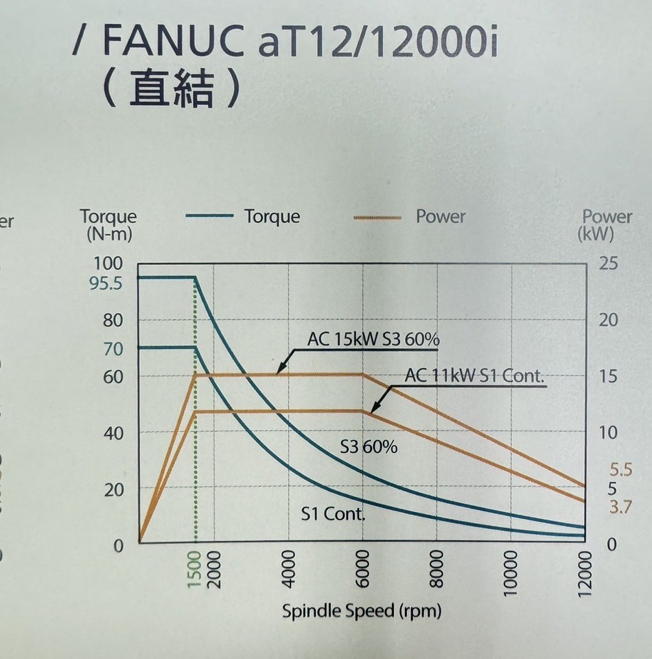
- Speed–power–torque diagram — the spindle's power (kW) and torque (Nm) against RPM, including duty ratings (e.g. S1 continuous / S6 / 15-minute). From the machine or spindle spec sheet. Required for power, torque, and spindle-overload analysis.
This is the kind of chart needed — power and torque vs spindle speed, with the continuous (S1) and short-duration (S3) ratings:
Tip
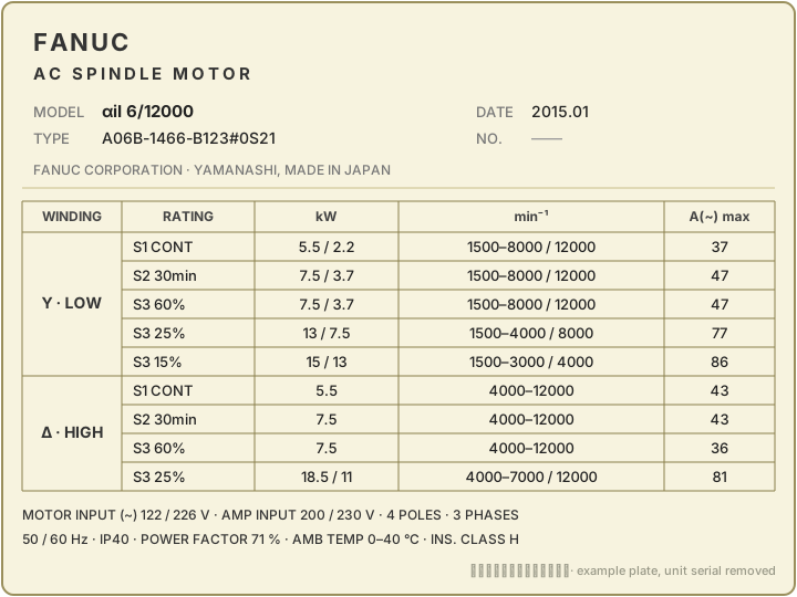
Easier than transcribing: photograph the spindle motor nameplate. The same ratings are printed on the spindle motor's spec nameplate, usually attached to the machine (on the spindle or motor body). A clear photo of it is enough — the model, type, and the S1/S2/S3 rating table (kW and speeds) recover the power–torque behaviour. Example (a FANUC αiI 6/12000 plate, unit serial removed):
See Spindle Capability.
3. Environment
- Coolant type — which coolant is used. Optional — if omitted, a default coolant setting is applied. The remaining coolant/thermal values (temperature, convection, background temperature) keep their defaults too; they only affect thermal and wear results.
See Coolant.
4. Workpiece
- Material — a named material from the database, or its mechanical/thermal properties. Required.
- Raw (stock) geometry — STL or simple parametric dimensions (e.g. block
120 x 80 x 40or round billetØ65 x 50). Used for the starting shape and size. Required. For a casting or forging, give the as-cast shape as an STL and note its casting tolerance (the stock scatters part-to-part). Finished/design CAD is optional, used to compare the simulated shape against the target (geometry validation). - Program-zero position, in plain words — where each work offset (G54, G55…) sits on the part, e.g. “G54 = top centre of the stock; Z0 at the top face, X0/Y0 on the axis”. Required.
Note
Describe the program zero by position on the part, not the machine-coordinate offset numbers — for evaluation/planning a relative or assumed alignment is fine and HiNC aligns it for you. See Program Zero Alignment.
5. Fixture
- Fixture CAD/STL — optional, only needed when the fixture participates in collision detection.
6. Tooling
For each tool used by the program, collect:
- Cutter brand + product ID — the maker and catalog number (with datasheet/link if handy). The single most useful field, when the cutter has one: from it the engineer looks up the geometry, flute count, helix, and grade, so give it even if the geometry below is incomplete. Off-brand cutters with no brand, manual, or traceable vendor are common (it depends on the shop) — then skip this and provide the geometry below directly, measured if needed.
- Cutter geometry — Required (or derivable from the brand + product ID above):
- type (flat-end / ball / corner-radius / insert), diameter
D, corner radiusR - flute (cuttable) length — the cutting portion
- overall tool length / stick-out — how far the cutter reaches from the holder to the flute tip; this sets where the holder grips and affects deflection and reach. A plain cylindrical cutter can use a small default exposed length (~5 mm); a cutter that is not a simple cylinder — a stepped or necked shank, or a body wider than the cutting diameter — needs a longer stick-out so the wider non-cutting part clears the workpiece.
- flute count, helix angle, rake angle (relief angle if known)
- type (flat-end / ball / corner-radius / insert), diameter
- Cutter & coating material — body material and coating layers. Required.
- Holder — give the brand + product ID, or at least a rough height + radius (e.g.
Ø40 x 60 mm). Full CAD is optional and only needed for collision detection; the rough size is enough to see whether the holder would hit the workpiece and how deep the tool can reach. Where the holder grips the tool comes from the cutter's stick-out above, so the tool can be placed even without holder geometry.
Tip
The cutter brand + product ID (or a datasheet image) is usually faster and more reliable than transcribing every dimension — the engineer reads the geometry off the catalog.
See Cutter, APT Tool, Insert Cutter, and Smart Tool Holder.
7. Controller
- CNC brand/type — determines how the NC code is interpreted. Required.
- NC / CL program(s) — the actual programs that run on the machine. Required.
- Work offsets (G54…) and tool offset table — not required for evaluation/planning. Relative or estimated values work; HiNC can set a workable assumed tool offset for you. Provide the real values only when a high-fidelity match is needed.
- Stroke limits and machine-specific configuration parameters — optional.
See ISO / General NC and Heidenhain Support.
Delivery Formats
| Data | Preferred format |
|---|---|
| Machine / fixture geometry | STL, all exported from the same coordinate system (see Machine Tool best practices) |
| Workpiece geometry | STL (stock + finished) or parametric dimensions |
| Cutter | Brand + product ID (best), or geometry parameters / datasheet image |
| Holder | Brand + product ID, or rough height + radius |
| Spindle capability | Brand + model, plus spec-sheet table or chart image (power & torque vs RPM) |
| NC program | The original .nc / .cl files |
Examples
The examples below show how to write it. Provide the item values together with the CAD and NC files; mark estimates, and give the spindle model and cutter brand + product ID where you can, so the engineer can fill any gap.
These files include spindle chart photos, cutter catalog pages (e.g. cmtec-CEXCRSH3120005.pdf), CAD (STL/STEP), and NC programs; note the filename next to the matching item.
Example 1 — Pocketed plate, 3-axis, steel
# Cover plate — TMV-720A 3-axis

Pocketed S50C cover plate roughed and finished on a 3-axis vertical machining center (VMC).
Goal: verify spindle load on the deep pocket and trim cycle time.

## Machine
Model:      TongTai TMV-720A, 3-axis VMC
Tool mount: (0, 0, 0) mm (where the tool is equipped; taken as the reference point)
Table mount: (-450, -340, -630) mm (fixture & workpiece, relative to the tool mount)
Controller: Fanuc
Strokes:    X720 Y420 Z460 mm ; rapid 20000 mm/min ; max spindle 8000 rpm

## Spindle
Brand/model: TongTai TMV-720A standard 8000 rpm spindle (BT40)
Source:      TMV-720A catalog power–torque chart — attachment fanuc-at12-12000i.png (15-min rating below; with the image you need not transcribe these)
Power  (kW vs rpm): 0@0, 7.5@1500, 7.5@4500, 4@8000
Torque (Nm vs rpm): 50@1500, 37@2000, 30@2600, 19@4000, 12@6000, 8@8000

## Workpiece
Raw stock: block 140 x 90 x 50 mm
Design:    cover-plate.stl
Material:  S50C

## Program zero
G54 = top centre of the block — Z0 at the top face, X0/Y0 at the block centre.

## Fixture
Machine vise — vise.stl, clamps below the part top (collision only).

## Coolant
Water-soluble emulsion (flood)

## Tools
T1  face mill   brand NTM, product TXE1000 (D50, exact P/N missing)
    D50  6 inserts  flute 6  tool length 60  holder Ø60 x 50 mm  stick-out 80
T2  flat end    brand cmtec, product CEXCRSH3120005 (catalog: cmtec-CEXCRSH3120005.pdf)
    D12  R0  4 flutes  helix 30°  rake 10°  flute 30  tool length 90  holder Ø40 x 63  stick-out 95
T3  flat end    brand cmtec (no exact P/N)
    D6   R0  4 flutes  helix 30°  flute 20  tool length 70  holder Ø25 x 60  stick-out 75

## NC Files  (folder `NC/`)
O0010.NC  face + rough the pocket with T1/T2 — watch spindle load near the deep pocket
O0020.NC  profile + floor finish with T3
Example 2 — Relief part, 5-axis, aluminum
# Airplane relief — 5-axis VMC

Airplane + logo lettering milled from a round Al6061T6 billet on a
5-axis vertical machining center (VMC). Goal: check the 5-axis toolpath for collisions/gouges, then optimize feed.

## Machine
Model:      5-axis VMC (example machine)   (machine file: MachineTool/Vmc5x/Vmc5x.mt)
Config:     table-C / spindle-B (C rotary on the table, B tilt on the spindle head)
Pivots:     C at (0, 0, 0), B at (-70, -180, 220) mm (relative to the C pivot)
Tool mount: (-70, 70, 175) mm (where the tool is equipped)
Controller: Fanuc
Strokes:    unbounded for this study ; rapid 20000 mm/min ; max spindle 8000 rpm

## Spindle
Brand/model: built-in 8000 rpm spindle, ~5.5 kW (BT30 class)
Source:      machine builder spindle datasheet (power–torque chart; attachment b1-spindle-chart.png)
Power  (kW vs rpm): 0@0, 5.5@1500, 5.5@4500, 3@8000
Torque (Nm vs rpm): 50@1500, 30@2000, 20@3000, 15@4000, 8@6000, 5@8000

## Workpiece
Raw stock: round billet Ø65 x 50 mm
Design:    airplane.stl
Material:  Al6061T6

## Program zero
G54 = top centre of the billet — Z0 at the top face, X0/Y0 on the axis. (G55+ unused.)

## Fixture
Round fixture Ø100 x 10 mm under the billet (collision only).

## Coolant
Air blast (dry)

## Tools
<!-- brand given but NO product ID, so the engineer recovers the exact geometry
     and grade by measurement — slower and more error-prone. A brand + product ID
     is very helpful when the tool has one; off-brand tools without one must be measured. -->
(all: brand cmtec, aluminum grade — product ID not given; carbide, 3 flutes,
 helix 37°, rake 15°, relief 5° [helix/rake estimated];
 holder Ø25 x 60 mm, 8 mm flute-to-nose clearance)
T1  flat end  D6  R0   flute 20   tool length 75
T2  ball end  D6       flute 20   tool length 75
T3  ball end  D3       flute 20   tool length 75
T4  ball end  D2       flute  8   tool length 75

## NC Files  (34 programs in folder `NC/`; actual filenames below)
  01-ED6L20.NC, 02-ED6L20.NC … 10-ED6L28.NC   roughing with T1 (flat D6)
  11-R3L25.NC … 22-R3L25.NC                    semi-finish with T2 (ball D6)
  23-R2L25.NC … 30-R2L25.NC                    finishing
  airplane-R1L12.NC, logo1-R1L12.NC, logo2-R1L12.NC, logo3-R1L12.NC   detail airplane + logo with T4 (ball D2)
(filename = seq-toolcode+cutlength; ED6 = flat end mill D6, R3/R2/R1 = ball, digit = nose radius)
Note
Example 2 mirrors a real .hincproj (machine name anonymized); Example 1 is representative with estimated values. The spindle model and the cutter brand + product ID are the anchors from which the engineer recovers the geometry and the power–torque chart.
See Also
- Workflow: Basic Machining Simulation — set up and run a simulation once the data is collected
- Machine Tool — build the kinematic model from CAD
- Program Zero Alignment — how HiNC aligns the program zero
- Spindle Capability — the speed–power–torque model