Spindle Capability
SpindleCapability (API) describes the energy, torque, power, and thermal envelope of a machine spindle. It is loaded as XML (.SpindleCapability files under Resource/SpindleCapability/) and lives on SpindleCapability (API) as part of the project equipment. This page explains what the model represents physically and how the per-step ratios on a machining step are derived.
For editing values interactively, see Spindle Capability Page. For empirical validation of the resulting power numbers against Fanuc ServoGuide, see Spindle Power Evaluation.
Boundary curves: continuous vs instantaneous
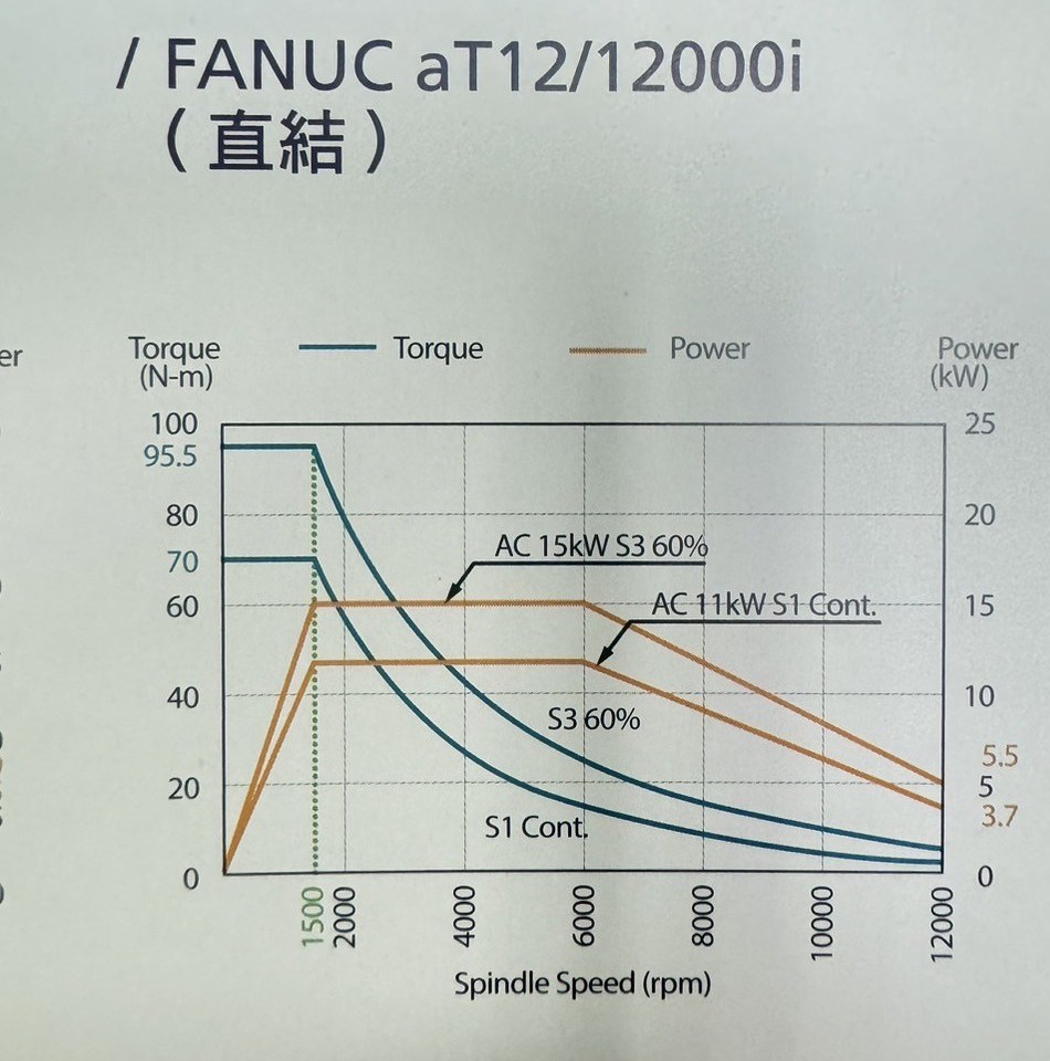
A typical spindle datasheet chart (FANUC aT12/12000i, shipped as FANUC-aT12-12000i.SpindleCapability): torque (N-m) and power (kW) plotted against spindle speed. The S1 Cont. curves are the continuous boundary; the S3 60% curves are a short-duration rating. HiNC stores exactly these curves, keyed by workable duration.
The capability stores two dictionaries keyed by workable duration (in minutes), mapping spindle speed to the maximum power or torque the spindle can deliver for that duration:
- WorkableDurationToSpindleSpeedPowerContoursDictionary_min_cycleDs_kW (API)
- WorkableDurationToSpindleSpeedTorqueContoursDictionary_min_cycleDs_Nm (API)
Two duration keys are special:
PositiveInfinity— the continuous boundary. The spindle can run at any (speed, value) point on this curve forever without overheating. Industry usage often calls this the S1 rating.- The smallest finite key (e.g.
15) — the instantaneous boundary. The spindle can run at any (speed, value) point on this curve only for that workable duration before the temperature ceiling is reached.
A capability typically also has intermediate keys (e.g. 60 minutes) which document the spindle's published rating curve.
Note
Why duration-keyed and not just two curves?
The duration key serves two roles. The contour values give peak load capability (used by the ratio computation, see below). The duration values implicitly encode the thermal time constants (used by the thermal envelope, see further below). One family of curves drives both.
If GearShiftSpindleSpeed_rpm (API) is set, each contour is treated as two segments split at that speed; only the segment for the current spindle speed is used for interpolation. Outside the segment, interpolation uses nearest-neighbour clamping rather than extrapolation.
How the four ratios are computed
For every machining step where the spindle speed changes, SpindleSpeedCache (API) interpolates each of the four contour-based curves at the current spindle speed and stores four scalar boundaries:
| Boundary (denominator) | Source contour |
|---|---|
MinInsistentRatioSpindleTorqueBoundary_Nm |
smallest-key entry of the torque dictionary, interpolated at current rpm |
InfInsistentRatioSpindleTorqueBoundary_Nm |
∞-key entry of the torque dictionary, interpolated at current rpm |
MinInsistentRatioSpindlePowerBoundary_W |
smallest-key entry of the power dictionary, interpolated at current rpm |
InfInsistentRatioSpindlePowerBoundary_W |
∞-key entry of the power dictionary, interpolated at current rpm |
The four MachiningStep ratios are then divisions:
Because the continuous boundary is always lower than (or equal to) the short-duration boundary, the corresponding Continue- ratio is always greater than (or equal to) its Max- counterpart for the same load:
- A
Max-ratio above 100% means the spindle is overdriven instantaneously and will trip thermal protection within the rated short duration. This is the criterion MaxSpindleTorqueRatio (API) and MaxSpindlePowerRatio (API) use to flag tool breakage on Process Machinability. - A
Continue-ratio above 100% means the spindle cannot sustain this load forever — short bursts may still be safe. Useful for pacing long operations rather than predicting immediate failure.
Input power vs output power
The power numerator above is input power (energy entering the spindle), not output power (energy reaching the cutting end). They are related by the spindle's energy efficiency:
\(\text{inputPower\_W} = \frac{\text{AbsAxialPower\_W}}{\text{EnergyEfficiency}}\)
— where EnergyEfficiency is EnergyEfficiency (API) and AbsAxialPower_W is what the cutting actually demands. The lost fraction \((1 - \text{EnergyEfficiency})\) becomes heat that the thermal envelope has to dissipate.
Spindle Power Evaluation documents the empirical justification for this conversion against measured Fanuc ServoGuide TCMD data.
Dry-run idle power
Even when the cutter is in air, a rotating spindle dissipates power as bearing friction and aerodynamic windage. HiNC models this as a sum of a linear-in-rpm term (bearing friction) and a higher-order term (windage), parameterised by:
- DryRunFrictionPowerCoefficient_mWdrpm (API) — friction term coefficient
- DryRunWindagePowerCoefficient_pWdrpm3 (API) — windage term coefficient
The friction term dominates at low rpm; the windage term takes over at high rpm. The thermal envelope (next section) uses the larger of the dry-run idle power and the cutting-induced heat, so the spindle keeps warming up even during air moves.
Thermal envelope
The same SpindleCapability also drives a thermal model of the spindle body. You do not set heat capacity or convection directly — the thermal model is auto-calibrated from your existing inputs.
- The continuous (
∞-key) curve plus WorkingTemperatureUpperBoundary_C (API) together determine how fast the spindle dumps heat at steady state. Physically: the continuous rating is, by definition, the load the spindle can hold forever without exceeding the working-temperature ceiling — so HiNC infers the steady-state heat-loss capacity from this constraint. - The shortest-duration curve plus its duration key together determine how much heat the spindle can absorb before reaching the ceiling. Physically: the short-duration rating is, by definition, the load that brings the spindle to the ceiling exactly within that workable time — so HiNC infers the body's effective thermal mass from this constraint.
What this means for you: refining the contour data (more accurate (speed, power/torque) points, better matched duration keys) automatically improves both load-capacity prediction and thermal-response speed. There is no separate thermal parameter to tune.
Per-step temperature outputs
At each step the body temperature evolves under whatever heat input is currently applied (cutting losses or dry-run, whichever is larger), approaching the steady-state temperature implied by that heat input. The two outputs published per step are:
- SpindleTemperature_C (API) — current body temperature
- SpindleWorkingTemperatureRatio (API) — body temperature normalised so that ambient is
0and the working-temperature ceiling is1. A value approaching1.0means the spindle is near its thermal limit.
Note
SpindleWorkingTemperatureRatio describes the spindle housing as a whole. It is not the same as the cutter-edge thermal failure tracked by ThermalYieldRatio in Process Machinability, which is a localized cutting-edge phenomenon.
Editing and file IO
Capabilities are persisted as XML (.SpindleCapability files). Three pre-built spindles ship in Resource/SpindleCapability/:
FANUC-aT12-12000i.SpindleCapabilityTMV-720A-STD-8000RPM.SpindleCapabilityVP-8--Fanuc-10000RPM.SpindleCapability
To edit values interactively, see Spindle Capability Page in the Quasar webservice. The desktop WPF app does not yet have a dedicated editor; load capabilities through the equipment's ObjectManagementMenuButton instead.
Related pages
- Process Machinability — uses
MaxSpindleTorqueRatio/MaxSpindlePowerRatiofor tool-breakage prediction - Spindle Power Evaluation — empirical validation of HiNC spindle power against Fanuc ServoGuide measurements
- Step Field Reference — full list of per-step physics outputs
- Spindle Capability Page — UI editor walkthrough