Three-Axis Milling Benchmark, Parts 1–3: From Published CAM Data to an Accepted Simulation
An AI agent took parts 1–3 of a published three-axis milling benchmark, for each a STEP model, a CAM program and a rendering and nothing more, and built them into HiNC projects through the web API, choosing and recording what the data set leaves out and correcting the one thing it gets wrong. All three programs play unchanged on HiNC 3.2.45 and pass acceptance on evidence, first at a coarse Machining Resolution of 1 mm (the edge of the cubes the simulated stock is built from; finer is slower and needs more memory, see Mesh Resolution) and then at 0.25 mm. The agent wrote its procedure down as a build guide and proved it with four independent agents that saw nothing else.
Everything here is simulated: no part was cut on a real machine. The page records the fourteen dilemmas the agent met (D1–D14, cited by number throughout), each with its risk, how it came to light, its resolution and the evidence that the resolution held. The built projects were the agent's working material and are not distributed.
The case
The data set is Benchmark Dataset of 10 Multi-Feature Models for Single-Setup 3-Axis Milling by
M. Schmitz, J. Mertes, F. Schillinger and M. Wagner: Zenodo record
17035762, version 1, 2025-09-02, DOI
10.5281/zenodo.17035762, licence
CC BY 4.0. Its ten parts are each cut from one
80 × 80 × 50 mm block with one end mill of at most 6 mm and no re-clamping, and each comes as a
.step model, an .ngc program and a .png rendering; the record's MD5 checksums matched all nine
files of parts 1–3. Peer agents built parts 4–10 with the same guide, as
a case of their own.
| Part | Features (the record's table) | The geometry | Program | Operations |
|---|---|---|---|---|
| 1 | Slots | one straight slot 6 mm wide and 6 mm deep, through along X | 6,887 bytes, 320 lines; deepest Z−7 | PLANEN1 facing, NUT2 slot |
| 2 | 4 holes | four Ø10 blind holes 4 mm deep on a 50 mm square | 14,483 bytes, 514 lines; deepest Z−5 | PLANEN2 facing, 2D-TASCHE1 helical holes |
| 3 | 4 holes, surrounding step (rectangular) | a 70 × 70 mm square standing 4 mm proud, with four Ø10 holes 7 mm deep | 36,113 bytes, 1,333 lines; deepest Z−8 | PLANEN2 facing, 2D ADAPTIVE2 step clearing, 2D-TASCHE1 holes |
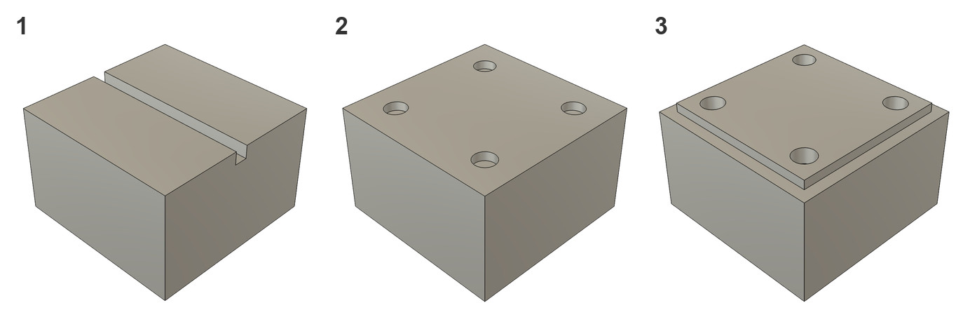
Parts 1–3 as the data set renders them, one .png file per part: the finished part that each .ngc
program cuts from the block and each .step model describes.
Every program uses one tool, (T1 D=6. CR=0. - ZMIN=… - SCHAFTFRSER), a Ø6 flat end mill, names its
operations in German and runs S18000 for the facing (and part 3's adaptive clearing), S16000 after.
Feed-path cutting times summed from the programs: 2.8, 4.8 and 7.3 min. Only part 2 has a machine
header (HERSTELLER AUTODESK, MODEL GENERIC 3-AXIS); the .ngc extension, G64 P Q and G91.1
point to a LinuxCNC post-processor, an inference the record does not state.
The data set does not give the material, the machine, the spindle, the holder, the tool beyond D=6 and CR=0, or where program zero sits: the models are centred on X/Y 0 and span Z 2 to 52, and the programs use another origin (D2). One stated value does not fit: the programs need a block 51 mm high, not 50 mm (D3).
What the agent built
Everything went through HiNC's web API, following the public pages Project Construction (build order and rules), Driving the Web Service over HTTP (the calls) and Replay Acceptance (the runs), not internal notes. Each value is marked read (stated by the source), derived (worked out from it by the agent), chosen (the agent's choice where the source is silent) or measured (in a run).
| Item | Set-up | Basis |
|---|---|---|
| Machine | the shipped generic three-axis chain with no shapes; table placed by a static translation (−400, −250, +400); travel X −800..0, Y −500..0, Z −500..0 | Chosen: the cut does not depend on the machine's looks (D5); placement derived for this chain: its tool end carries +1000 mm, so the table goes at +400, 600 mm below it (Building Virtual Machine Tools) |
| Fixture | a 160 × 120 × 20 mm plate, the workpiece mount on its top face | Chosen: the data set names no clamping |
| Stock | a box 80 × 80 × 51 mm at X 0.5..80.5, Y 0.5..80.5, Z −51..0 in program coordinates | Derived: the height the programs need (D3) |
| Design model | STEP converted to STL (cascadio, trimesh; the glTF step is in metres), moved by (40.5, 40.5, −53); closed meshes of 28, 1,148 and 1,164 triangles | Read, placed by a derived translation (D2) |
| Program zero | the workpiece frame's origin; fixture mount at (40.5, 40.5, −51); G54 (−440.5, −290.5, −529), written by P0, HiNC's program-zero call (set-to-program-zero, the P0 button on a work-offset row), which measures the offset from the placed model |
Derived from the toolpaths (D2); the G54 as P0 returned it |
| Controller | Fanuc brand, programs unchanged | Chosen: HiNC has no LinuxCNC brand, and its Fanuc reader leaves only two kinds of harmless warning (D1) |
| Material | Al6061-T6 from the shipped library; cutter material WC-Co10-600nm | Chosen: the record names none |
| Tool | Ø6 flat end mill: flute 13 mm, overall 57 mm, 3 flutes, helix 45°, radial rake 12°, radial relief 10° | Read: D=6, CR=0; chosen: the rest, in realistic proportions |
| Holder | shrink-fit chuck, Ø21 nose, 4.7° taper, gauge length 80 mm; Z–R profile (0, 10.5) (55, 15) (55, 22) (63, 22) (63, 31.75) (80, 31.75) | Chosen: the shipped holder file is not used (D5) |
| Stick-out | max(flute length, deepest cut) + 5 mm, rounded up to a multiple of 5: 20 mm on all three parts; tool length 100 mm | Chosen rule (D5); 20 mm derived; 100 mm read back from the offset row (idealHeight) |
| Spindle | a synthesized generic 24,000 rpm spindle: 7.5 kW continuous, 10 kW short-term, constant power from 4,000 to 24,000 rpm | Chosen: the library's spindles stop at 12,000 rpm; the programs ask for 18,000 (D4) |
| Mission | Machining Resolution 1 mm for a datum run, then 0.25 mm for acceptance; collision detection on; geometry difference at the end | Chosen: coarse before fine (D8) |
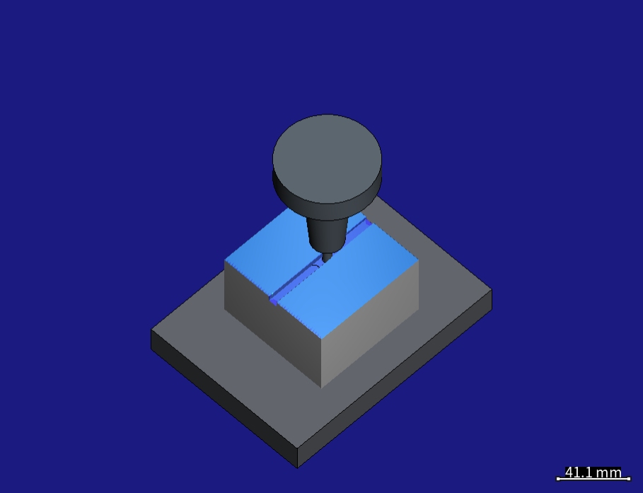
Part 1, paused at step 50,367 of 52,600 in the Z−5 layer of the slot (Execution page, isometric view, tool path hidden): the shrink-fit holder, gauge length 80 mm, holds the 6 mm end mill at a 20 mm stick-out.
How the agent managed the work
- Evidence, not status. Every replay was judged on the public Replay Acceptance checks plus a message inventory by id and count (D7). Each part's reference numbers went into its notes, so the four independent builds were judged against numbers fixed before they ran (D10).
- Coarse before fine, with memory estimated first: 1 mm to check the datum in seconds, then 0.25 mm for acceptance (D8).
- A research sub-agent in parallel read the parser source for each LinuxCNC word while the agent replayed part 1; the brand was settled once both agreed (D1).
- Independent agents proved the written guide, a sequence of API calls each followed by a read-back: four rebuilt parts from the guide, one case's files and a server address alone, and every guess they had to make became guide text (D10).
- Peer findings folded in. Peer agents used the guide at the same time for parts 4–10 (all fourteen replays passed), the THWS keychain, a Siemens-programmed part, and a NIST five-axis artifact (D2, D10).
- Adversarial review. A peer agent's claim-by-claim review of the parts 4–10 notes flagged three statements that parts 1–3 shared; the agent corrected them the same day (D12).
- A shared server. Several agents worked on one HiNC server at once; each used its own service instance and key prefix and never stopped a run it had not started (D13).
- Where a person stepped in. HiNC's product owner, who directed the work, set these rules, and
each changed what the agent did:
- A realistic holder at the shortest stick-out that is enough, because a cutter hanging out of the spindle with no holder would break. The agent defined its own holder, stick-out rule and check (D5), and every HiNC picture here shows the holder.
- No client material: the shapeless generic machine, and a holder defined inside the project (D5).
- Build from the public documentation: the agent followed the public pages named above, not internal notes.
- One root folder per topic, and a record rather than a training kit: each case's sources, notes and built project sit in its own folder, laid out the same on every machine (D14), and the guide, the notes and the blind builds are kept as the record of how the agent proved its work.
The dilemmas
Fourteen, in the order they came up, each told as situation, risk, how it was noticed, resolution and the evidence that the resolution held.
| Dilemma | What resolving it prevented | |
|---|---|---|
| D1 | No controller brand reads LinuxCNC | an edited program hiding behaviour |
| D2 | Program zero is not given | a wrong placement that still cuts |
| D3 | The stated block is 1 mm short | a false layer of missing material |
| D4 | Library spindles stop at 12,000 rpm | power figures from a spindle too slow |
| D5 | Shipped holder and machines with shapes not used | a set-up no machinist would run |
| D6 | P0 fills one of two offset tables | the page's marker contradicting the run |
| D7 | “Finished” is not “passed” | accepting a run that cut nothing |
| D8 | Fine runs cost time and memory | fine runs spent on a wrong datum |
| D9 | Part 1's depth peak doubles at 0.25 mm | “fixing” a correct datum |
| D10 | Does the guide work without its author? | silent differences between builds |
| D11 | Line-ending conversion changed the sources | checksums that no longer match |
| D12 | Attribution statements | a wrong licence claim |
| D13 | Several agents on one server | one agent's reset destroying another's run |
| D14 | One topic in two folders | not knowing which build a result came from |
Reading the data
D1. No controller brand matches the dialect
- Situation. The programs are LinuxCNC-style (
G64 P Qblending,G91.1incremental arc centres,G18 G3 … I Kramps,G53 G0 Z0); HiNC's brands are Fanuc, Siemens, Heidenhain, Syntec and Mazak. - Risk. Editing the programs to “fix” the words would change the published program and hide how the controller treats them.
- How it was noticed. No brand matched. A research sub-agent read the parser source word by word while the agent replayed part 1 on Fanuc; the two agreed.
- Resolution. Fanuc, programs unchanged.
G91.1changes nothing, since Fanuc's I/J/K are always incremental.G64 P Qis LinuxCNC's path-blending tolerance, which on a real LinuxCNC control lets corners round off; the simulation does not model it and follows the programmed path. Both raiseParsing--Unconsumed;G18 G3with I/K,G53 G0 Z0,%and comments raise nothing. By the public rule, constructs that raise a known message without changing the motion stay as delivered, listed as expected messages (Project Construction §1): two per play on part 1, which has oneG64block, and three on parts 2 and 3, which have two. A repeated message is not listed again; its later occurrences become one[repeated 2x in this run, …]entry on the last block where it occurs, counted as one. - Evidence. Every replay, the agent's and the blind builds', raised exactly these entries beside the file-length note and executed every line.
The nc entries each part's notes expect per play; the step and NC-manipulation lists stay empty:
| Part | Sys-Init--FileLines |
Parsing--Unconsumed |
Where |
|---|---|---|---|
| 1 | 1 (320 lines) | 2 | G91.1 at block N10; Q, P, G64 at N45, the one G64 block |
| 2 | 1 (514 lines) | 3 | G91.1 at N10; Q, P, G64 at N45, and again at N1505, reported as [repeated 2x in this run, …] |
| 3 | 1 (1,333 lines) | 3 | G91.1 at N10; Q, P, G64 at N45, and again at N1500, reported as [repeated 2x in this run, …] |
D2. Where is program zero?
- Situation. The STEP models are centred on X/Y 0 and span Z 2 to 52; the programs' zero is elsewhere, unstated.
- Risk. A wrong placement still cuts something, so a run can pass a shallow check.
- How it was noticed. Toolpaths against model features: part 1's slot pass runs at Y40.5 and the slot is one tool diameter wide; part 2's radius-2 helical hole arcs (Ø10 holes, Ø6 tool) are centred at X/Y 15.5 and 65.5, the model's holes at ±25; part 3's adaptive layers are centred on 40.5. In Z the model's top lands on Z−1, the facing depth, every floor on a Z the program cuts at, and the deepest on the tool comment's ZMIN.
- Resolution. The model moves by (40.5, 40.5, −53). Program zero sits 0.5 mm outside the model on each side and 1 mm above it, which points (an inference) to a CAM stock that much larger with zero at its top-front-left corner. A peer agent on parts 4–10 first found 40 from floors alone; side features showed 40.5, an error floors cannot see. The rule: check X and Y on side features.
- Evidence. The placed models span [0.5, 0.5, −51] to [80.5, 80.5, −1], flush with the stock's sides and bottom; part 1's coarse depth peak is exactly its 2 mm layer (D9).
D3. The stated block size contradicts the program
- Situation. The record gives 80 × 80 × 50 mm. The programs face 1 mm off the top, and the 50 mm model below that face ends at Z−51.
- Risk. The geometry difference would report a 1 mm layer of missing material under every part that no program could cut: a false alarm.
- How it was noticed. From D2's arithmetic: Z−51 is below a 50 mm block topped at Z0.
- Resolution. An 80 × 80 × 51 mm stock, flush with the model's sides and bottom, 1 mm above its top; each part's source notes say so and why.
- Evidence. Stock and model share their bottom at Z−51, leaving no layer to report.
Setting up
D4. The library's spindles cannot turn fast enough
- Situation. The shipped spindles stop at 12,000 rpm; the programs ask for 18,000.
- Risk. Power or torque at that speed would come from a spindle that cannot reach it.
- How it was noticed. Comparing the programs'
Swords with the library. - Resolution. A spindle labelled generic, taken from no vendor's sheet: 24,000 rpm, 7.5 kW continuous, 10 kW short-term, constant power 4,000–24,000 rpm (Spindle Capability).
- Evidence. S16000 and S18000 lie in its constant-power range; no replay raised a message outside the expected list.
D5. The shipped holder and machines with shapes are not used
- Situation. Every tool needs a realistic holder, but the case uses neither the one shipped holder file nor a shipped machine with shapes; the cut does not depend on the machine's looks.
- Risk. The engine plays a tool with no holder without a word, so a case could show a set-up no machinist would run.
- How it was noticed. The owner's case rules ruled the shipped files out; nothing in the engine would have flagged a missing holder.
- Resolution. A shrink-fit chuck defined in the project by its Z–R profile, the stick-out rule of
the set-up table, and a six-point check the agent computes and reports: (1) nose wider than the
cutter; (2) stick-out at least the flute length; (3) nose at least 5 mm above the stock top at the
deepest Z; (4) stick-out no longer than needed; (5) offset row = 80 + stick-out; (6) no
Collision--Detectedin the replays, from HiNC's collision check, which covers the fixture and also the holder and the shank against the stock. - Evidence. At the deepest Z the nose stays 13 mm above the stock on part 1 (Z−7), 15 mm on part 2 (Z−5) and 12 mm on part 3 (Z−8); every offset row reads 100; the collision check reports no contact in any replay, at either resolution.
D6. Program zero lands in only one of two tables
- Situation.
set-to-program-zerofills the offset table the run reads, not the legacy ISO table the Execution page's coordinate marker reads. - Risk. Run and marker would disagree about program zero, misleading anyone checking by eye.
- How it was noticed. The public construction workflow documents that the tables are not kept in step and that the marker reads the legacy one (Project Construction §4).
- Resolution. The guide writes the same G54 into both.
- Evidence. The agent's builds and all four blind builds read back the reference G54, (−440.5, −290.5, −529), and wrote the same row into the legacy table.
Verifying
D7. “Finished” does not mean “passed”
- Situation.
Finishedsays only that the mission reached its end. - Risk. A run that never mounts a tool finishes without cutting; status alone would accept it.
- How it was noticed. The failure mode is documented (Replay Acceptance §4); the agent built its checks on that list.
- Resolution. Acceptance on seven kinds of evidence: more than zero steps (a step is one spindle
revolution of the simulated run); an
IsTouchedpeak of 1; every line executed; the simulated time; the geometry difference built; a message inventory by id and count, where anything outside the expected list is a build defect; and a depth peak equal to the part's reference value. On part 1's coarse run that is the programmed 2 mm layer, which pins the Z datum (D9); on part 2 the 4 mm hole depth, where the last helical turn and the finishing circle meet the whole wall; on part 3 a recorded 3.93 mm, which falls in the hole milling but is not traced to a block (see Honest limits). - Evidence. All three parts passed every item at both resolutions, with 52,600, 84,637 and 126,971 steps.
D8. Fine runs cost time and memory
- Situation. Each part is replayed several times while the set-up is being proven.
- Risk. A fine run spent on a wrong datum, or a run that does not fit in memory.
- How it was noticed. Planned: the documentation says to run coarse first (Replay Acceptance §3), and Memory Planning gives the estimate.
- Resolution. Datum runs at 1 mm, acceptance at 0.25 mm. Memory by the Memory Planning formula: about 1 GB base, plus about 5 KB a step (0.26, 0.42 and 0.63 GB), plus the meshes, giving 1.4, 1.5 and 1.7 GB, well under an ordinary 8 GB PC.
- Evidence. On a 32-thread server the 1 mm replays take 15, 20 and 25 s and confirm the datum; the 0.25 mm replays take 30, 40 and 65 s, with the same step counts.
D9. The depth peak doubles at the finer resolution
- Situation. Part 1's depth peak is 2 mm at 1 mm resolution but 4 mm at 0.25 mm.
- Risk. Read as a datum error, the jump could get a correct placement “fixed”.
- How it was noticed. The agent listed the depth per step (
widthHint=0) and traced the 4 mm steps to their block. - Resolution. The slot is exactly one tool diameter wide, so at the finer resolution the flank rubs residual material that the layer above left on the walls. The datum check uses the coarse run; the part's notes give both values and why.
- Evidence. All 204 steps at 4 mm lie in block
N1545 X80.5of the Z−5 layer, every fourth step; the last layer has no such peak, and the coarse run's 2 mm layers peak at exactly 2 mm.
Proving the procedure with other agents
D10. Can another agent succeed with the written procedure alone?
Situation. The agent's builds ran on its own scripts and knowledge of every trap; the guide was written for others.
Risk. Knowledge only in its author's head forces a follower to guess, and every guess is a place where a build can quietly differ.
How it was noticed. The agent tested it. Four independent agents, each given only the guide, one case's files and a server address and told to read nothing else, built part 1, part 3, part 2 (in place, in its case folder) and part 1 again (over an existing project), each reporting where it had to guess.
Resolution. Every guess became guide text. Those that would have changed a result or hidden a failure:
- P0 must follow
Execution/reset: the run's copy of the set-up takes edits only at a session boundary, so a project played before otherwise gets a stale G54 (peer agents; run 4 confirmed). - A mistyped route answers a GET with 200 and the web page's HTML, not 404 (a POST gets 405), so a status check on a GET reads success (peer agents).
- Mission paths renumber after deletes and inserts (a stale path answered
CommandTypeMismatch), so entries are found by type in a fresh read (run 3). - With
widthHint=1each point'sxsis the step it ends at, and the first point spans the whole run (run 2 misread it); collision-preparation messages appear only on the first replay after a create or load (run 2); a[repeated 2x]message is one entry (run 3). - A new project's resolutions default to 0.125 mm (run 1).
- Steps ≈ minutes with the spindle turning × rpm; the feed time alone was 3 % low on part 1 and 36 % on the keychain (peer agents).
Smaller findings about the shape of answers (empty 200 bodies, canonical keys, nested lists) went in the same way. The rule that came out, while the guide was meant for others: a change to the procedure is proven by another independent run, not by rewording.
- P0 must follow
Evidence. All four builds passed every check with the reference numbers: 52,600 steps on part 1 (twice), 126,971 on part 3, 84,637 on part 2, with the same G54 and message inventories.
Working alongside other agents
D11. Keeping the source files byte-exact across machines
- Situation. The original files end their lines with Windows line endings (CRLF); a checkout set to convert them stored Unix ones (LF), changing the bytes though not the text.
- Risk. The copies would stop matching the SHA-256 checksums in the source notes, and the claim that the programs play exactly as published would break.
- How it was noticed. Before the first commit: the copies about to be stored had lost their CRLF.
- Resolution. Source files, the program copies the missions play and set-up files are stored unconverted.
- Evidence. The stored files match the checksums, and each program a mission plays is byte-identical to the original.
D12. Precise attribution
- Situation. Each part's source notes state authors, licence and provenance, and a public page repeats them.
- Risk. A wrong attribution or licence claim, published.
- How it was noticed. A peer agent's adversarial review of the parts 4–10 notes, one read-only reviewer per part, flagged three statements parts 1–3 shared.
- Resolution. Corrected the same day: CC BY 4.0 has no ShareAlike, so the program is covered as one of the record's files, not because an adaptation “inherits” a licence; the record gives the authors no affiliation, only its contact names an institution; that Autodesk's Fusion posted the programs for LinuxCNC is an inference, marked as one.
- Evidence. This page follows the corrected notes; the corner of the CAM stock, which a second round found still stated as fact in the parts 4–10 notes, is marked as an inference here (D2).
D13. Several agents on one server
- Situation. Several agents shared one HiNC server; each service instance holds one open project.
- Risk. One agent's reset, stop or close destroying another's run.
- How it was noticed. Another client once closed the project mid-replay, and the agent's poller waited on a state it did not recognise.
- Resolution. Own service instance and key prefix per agent, and no stopping a run it had not
started; the poller now stops on any state but
RunningorPaused. - Evidence. The interrupted run, simply repeated, gave the reference numbers.
D14. One root folder per topic
- Situation. Trial builds sat in a separate folder on the shared server, the case files in the case folders.
- Risk. With one topic in two places, which build a result came from is unclear.
- How it was noticed. The product owner saw the scattered folders.
- Resolution. Everything moved into each case's folder, laid out the same on every machine.
- Evidence. Each case folder holds its sources, notes and built project, and no build of these parts sits outside them.
Results and benefits
Measured on HiNC 3.2.45 by replaying each saved project at 1 mm and at 0.25 mm, except the memory (estimated beforehand, D8); the two HiNC pictures were captured on 3.2.40, and D9's per-step trace, taken while the parts were built, on 3.2.39. The same at 1 mm and at 0.25 mm unless noted. A step is one spindle revolution of the simulated run, so the count follows the spindle, not the resolution, and can be estimated beforehand as minutes with the spindle turning × rpm. Forces are context, not acceptance values, and rest on the assumed material and tool.
| Part 1 | Part 2 | Part 3 | |
|---|---|---|---|
| Steps | 52,600 | 84,637 | 126,971 |
| Lines executed | 320 / 320 | 514 / 514 | 1,333 / 1,333 |
Something cut (IsTouched peak) |
1 | 1 | 1 |
Peak cutting depth (CuttingDepth_mm) |
2 mm at 1 mm, 4 mm at 0.25 mm (D9) | 4 mm, the hole depth | 3.93 mm |
Peak cutting force (MaxAbsForce_N), 1 mm / 0.25 mm |
99.8 / 99.9 N | 54.5 / 54.5 N | 101.9 / 101.8 N |
| Simulated time | 177.3 s | 296.9 s | 447.9 s |
| Geometry difference built | yes | yes | yes |
| NC messages | 1 file-length note (Sys-Init--FileLines) + 2 Parsing--Unconsumed |
1 + 3 | 1 + 3 |
| Other message lists (step, NC manipulation) | empty | empty | empty |
| Replay on a 32-thread server, 1 mm / 0.25 mm | 15 s / 30 s | 20 s / 40 s | 25 s / 65 s |
| Estimated peak memory | 1.4 GB | 1.5 GB | 1.7 GB |
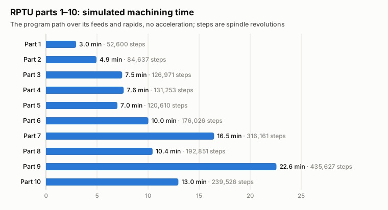
Simulated time and steps of all ten parts: parts 1–3 here, parts 4–10 in their own case.
Each program, operation by operation: the line of the comment that opens the operation, its steps, and its peaks at 1 mm / 0.25 mm, one value where both runs agree.
| Part | Operation (line) | What it cuts | Steps | Depth peak (mm) | Force peak (N) |
|---|---|---|---|---|---|
| 1 | PLANEN1 (7) |
1 mm off the top | 46,588 | 1 | 54.5 |
| 1 | NUT2 (302) |
the slot, in three 2 mm layers down to Z−7, the full tool width | 6,012 | 2 / 4 (D9) | 99.8 / 99.9 |
| 2 | PLANEN2 (11) |
1 mm off the top | 47,002 | 1 | 54.5 |
| 2 | 2D-TASCHE1 (307) |
the four holes, helically, down to Z−5 | 37,635 | 4 | 51.5 / 22.8 |
| 3 | PLANEN2 (7) |
1 mm off the top | 47,002 | 1 | 54.5 |
| 3 | 2D ADAPTIVE2 (303) |
the step around the square, in two 2 mm layers down to Z−5 | 16,935 | 2 | 101.9 / 101.8 |
| 3 | 2D-TASCHE1 (967) |
the four holes, helically, down to Z−8 | 63,034 | 3.93 | 57.5 / 26.2 |
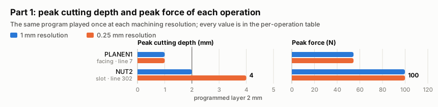
Part 1: only the slot's depth peak changes with the resolution (D9); its force peak does not.
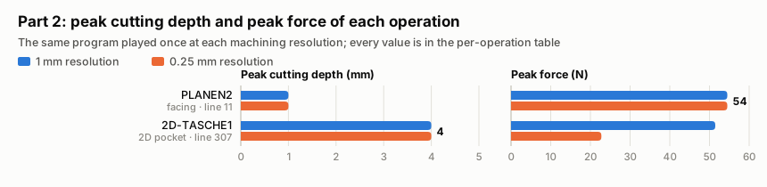
Part 2: the holes read their full 4 mm depth at both resolutions, and less than half the force at 0.25 mm.
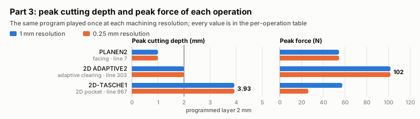
Part 3: the step clearing carries the force peak, the holes the 3.93 mm depth peak.
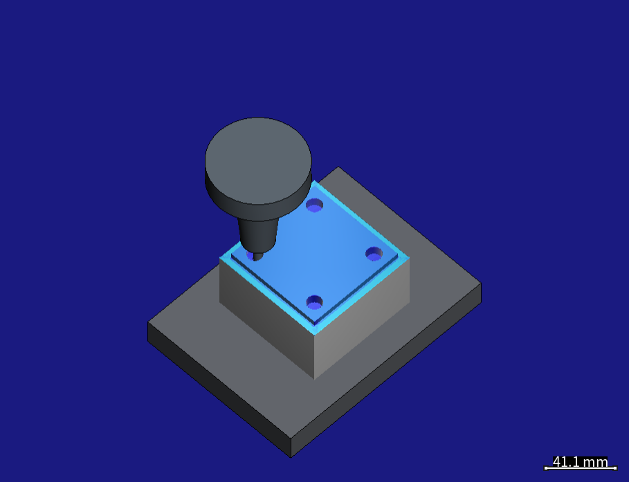
Part 3, paused at the fourth hole near step 121,000 of 126,971: the 4 mm step around the 70 × 70 mm island is cut and three of the four 10 mm holes are finished.
For a machining engineer. The programs play unchanged on HiNC's Fanuc-brand reader, whose only complaints are two kinds of known, harmless warning; that is the simulator's reading, and no real control was tested. Program zero, 0.5 mm outside the model on each side and 1 mm above it, and the block the programs really need, 80 × 80 × 51 mm, come from the programs before the first run. The simulated times include rapids but no acceleration (part 1's 177.3 s is 2.95 min against 2.83 min of feed path), so they are not machine cycle times. At 0.25 mm the full-width slot's flank reads a 4 mm contact depth where the layer above left material on the wall (D9). The peak force in the replays is about 100 N (99.8–99.9 N in part 1's full-width slot, 101.8–101.9 N in part 3's step clearing) for a Ø6 carbide mill in Al6061-T6, on the assumed material and tool geometry.
For a teacher or student. A worked example of turning published CAM data into an accepted simulation, with the checks that make it trustworthy (see What a reader can take to their own case); the guide, the notes and the blind builds show what proving an agent's work looks like in practice.
For someone deciding whether to use an agent.
- Supplied by people: the case rules and the owner's rulings (see How the agent managed the work).
- Delivered: three parts accepted at 0.25 mm; fourteen dilemmas, each recorded with how it was found and resolved; a procedure four independent agents followed to the same reference numbers, four times out of four.
- Cost: replays of 15–25 s at 1 mm and 30–65 s at 0.25 mm on a 32-thread server, in an estimated 1.4–1.7 GB of memory.
- Relied on: a research sub-agent (D1) and a peer's review (D12).
- Cannot tell: anything measured on a real machine.
Honest limits
- The material, tool geometry, holder, spindle and machine are assumptions, and the forces and power depend on them; nothing was measured on a real machine.
- The simulated time has no acceleration model, and
G64 P Qblending is not modelled. - Part 3's 3.93 mm depth peak is a recorded reference value; it falls in the hole milling at both resolutions, but is not traced to a block as part 1's 4 mm was.
- In the hole milling the force peak depends on the resolution: the 0.25 mm replays read less than half the 1 mm value (22.8 against 51.5 N on part 2, 26.2 against 57.5 N on part 3); the facing, slot and clearing peaks agree within 0.1 N.
- The placement (40.5, 40.5, −53) was derived for parts 1–3. Of the later parts, 4, 7 and 9 share it, 5, 6 and 10 sit at 41 in X and Y, and part 8's model needs a translation of its own, so the placement has to be derived for each part.
What a reader can take to their own case
- Recover program zero from side features, not floors: hole centres, slot centre lines and walls fix X and Y; floors fix only Z (Program Zero Alignment, Building the Workpiece from a Reference Mesh).
- Check the stock the program really needs, not the stated one: place the model first, then check that the stated block contains it (Geometry Validation).
- Keep the delivered program and list its known messages by id and count; edit a copy only when a construct changes the result (Project Construction §1, Replay Acceptance §5).
- Accept on evidence, not on “Finished” (Replay Acceptance §4).
- Run coarse before fine, and estimate memory first (Memory Planning).
- Check holder clearance from the geometry, and keep collision detection on, with a realistic holder at the shortest stick-out that is enough (Cutter, Cutter Geometry).
- Trace a surprising number to its block before correcting anything.
- Write down every assumption: what was assumed, what it was inferred from, and what changes when the real value arrives (Project Construction §7).
The data set is at its source, below.
Source and licence
The models, NC programs and renderings of parts 1–3 come from the Zenodo record https://zenodo.org/records/17035762; if the link fails, search for the data set's title or “zenodo 17035762”. The record gives the four authors no affiliation; its contact, Dipl.-Ing. Marius Schmitz, is at RPTU Kaiserslautern-Landau. The numbers and charts on this page were derived from these files by simulation, and the pictures are renders of that simulation, except the data set's own renderings of the three parts in The case.
Model, NC program and rendering: M. Schmitz, J. Mertes, F. Schillinger, M. Wagner, “Benchmark Dataset of 10 Multi-Feature Models for Single-Setup 3-Axis Milling”, parts 1–3, https://doi.org/10.5281/zenodo.17035762, licensed CC BY 4.0 (https://creativecommons.org/licenses/by/4.0/), provided without warranty. The simulation set-up is the agent's: the stock and the placement derived from the programs; the machine, spindle, tool geometry, holder and material chosen. The models were converted from STEP to STL and moved into program coordinates for the geometry difference; the NC programs were played unchanged; the renderings were cropped, set side by side and numbered.
This page offers no download; readers get the files from the source above. The company site keeps a copy of the original files only as a backup in case the original links stop working. The licence's legal code is at https://creativecommons.org/licenses/by/4.0/legalcode.
A file fetched from the record can be checked against the one simulated here by its SHA-256, as each part's source notes give it:
| Part | File | SHA-256 |
|---|---|---|
| 1 | 1.ngc |
8e48a4bf3647fc3319bd53fe131c411a1b7e79a7838605167795c916c7c71d29 |
| 1 | 1.step |
8c2142896328cb3af5d4bc7ea3ee8d9acec62d0128fab2f06d14fc4d81f7c349 |
| 1 | 1.png |
99ffdf93e07444ad1bfb86e967d6fe78784c3d4c144cd37b43785ec466f90a45 |
| 2 | 2.ngc |
4e45f52841ce0baaa4473cf3f80a276297ccbe4a7392b26927e6078acf64f11d |
| 2 | 2.step |
e6c3d7d0638ca832e59ab0d5d1c45bacb78c0738df76c19d5a64196cd831db45 |
| 2 | 2.png |
31c93f8753f8397d4ca4decd5d42f4f8ec74dfb3f1bc100df73861297bc5ff42 |
| 3 | 3.ngc |
5363a4888613a1732bacf9999958893a72b60481d919071214e992f770eccaec |
| 3 | 3.step |
872917f49b6c8cb458260571e45df3ffd8476c5e2dccb27121fefb16002f2991 |
| 3 | 3.png |
d08cada9191732b333764785c545db96f5397471eb458ee185f83cce33518687 |