NIST Five-Axis Test Artifacts: A Cone Frustum and a Pyramid from a Paper's Drawing
A NIST paper evaluates two parts for testing five-axis machine tools that an early draft of an international standard had introduced — a cone frustum and a truncated square pyramid — and gives their drawings and cutting conditions, but no model, no toolpath and no machine. No open-source CAM computes simultaneous five-axis toolpaths either.
An AI agent took the paper, drew both parts and wrote the cutter locations itself in a short Python script; then, through the HiNC web API, it let HiNC solve the axes of a five-axis machine, check it for collisions and write the Fanuc five-axis program, and replayed that program until it agreed with the toolpath it came from. On the way it met fourteen dilemmas. This page is the record, including the small problems.
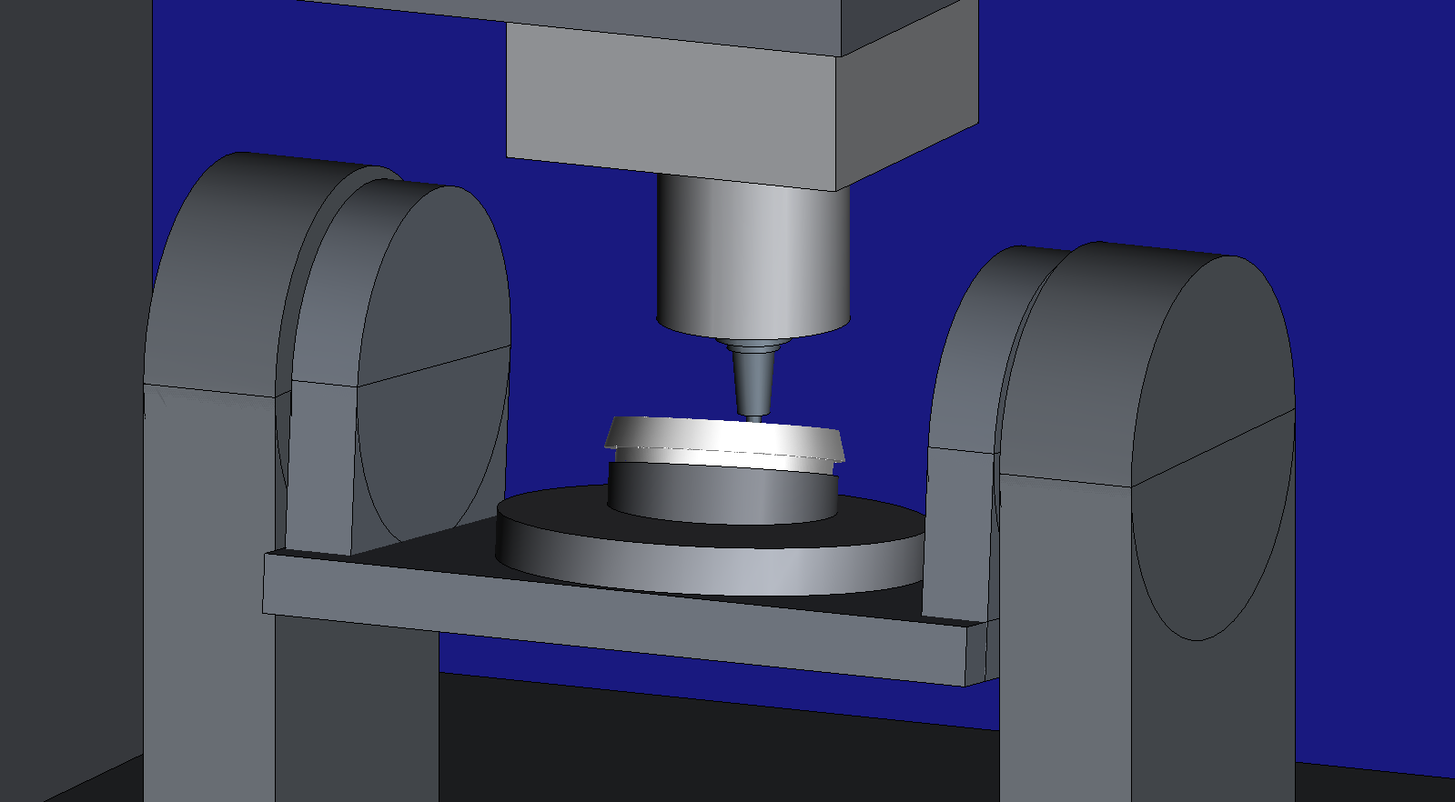
The case
The paper — by Moylan and co-authors from NIST and the Pennsylvania College of Technology, presented at the ASPE annual meeting in 2011 — evaluates two artifacts, introduced by an early draft of an international standard, that are finish-machined with the side of the cutter while all five axes move, because the part sits tilted on the machine's rotary table. It states:
- Two engineering drawings with bare numbers: lengths and angles, but not which dimension each number is.
- Cutting conditions: a 12.7 mm carbide end mill for aluminium, 300 m/min, 0.05 mm per tooth, a finish cut of 0.1 mm radial depth.
- Set-ups: the frustum tilted 10° or 15° about Y with its origin 50 mm from the rotary table's axis; the pyramid tilted 20° with its origin on that axis; on the pyramid the tool's centre line must always pass through the pyramid's axis, so the rotary axes move even on a flat face.
- Process: a blank about 5 mm oversize, roughing passes, then the finish pass.
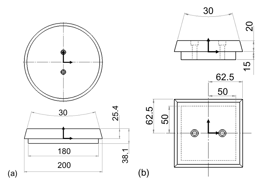
It leaves out the model, the stock, the fixture, the toolpath, the program, the holder, the flute count and length, the alloy, and the machine — the authors used one with a non-orthogonal tilting axis, inclined 45° from the Y axis, of which no model is available.
What the agent built
Each value is marked read (stated by the paper), derived (worked out from it) or chosen (the agent's choice where the paper is silent).
| Item | Cone frustum | Truncated square pyramid |
|---|---|---|
| Target model | Ø200 mm at the bottom, sides 15° from the axis, 25.4 mm tall, on a Ø180 × 12.7 mm pedestal — derived from the drawing | 125 × 125 mm at the bottom, faces 15° from vertical, 20 mm tall, on a 100 × 100 × 15 mm pedestal — derived (see the first dilemma) |
| Stock | Ø210 mm cylinder over the frustum, pedestal already finished — chosen to give the paper's 5 mm | 135 × 135 mm block, pedestal finished — chosen likewise |
| Fixture | a Ø190 mm wedge disc tilted 10°, 15 mm thick at its low edge — tilt read, shape chosen | a 114 mm square wedge tilted 20°, 15 mm thick at its low edge — tilt read, shape chosen |
| Program zero | on the part's axis in its bottom plane, 50 mm from the table's axis — read; axes parallel to the table — chosen | on the table's axis — read; axes parallel to the table — chosen |
| Toolpath | side milling along the cone's slant line, one revolution per pass, passes 10, 8, 6, 4, 2.1, 0.1 and 0 mm from the surface — last cut read, the rest chosen | each face with the tool axis through the pyramid's axis — read; passes 8 down to 0 mm — chosen |
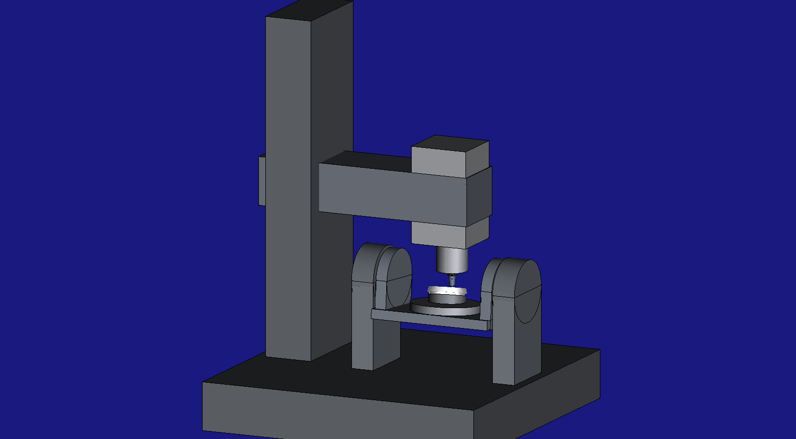
| Machine | a generic B/C table-table machine built of plain boxes and cylinders: B tilts about Y, C turns on the table — chosen | the same |
| Controller | Fanuc dialect; travel X ±400, Y ±300, Z −250 to 650 mm, B ±110° — chosen | the same |
| Material | aluminium — read; 6061-T6 — chosen | the same |
| Tool and holder | Ø12.7 mm carbide cutter for aluminium — read; flat end, 3 flutes, 45° helix, 12° radial rake, 10° radial relief, 32 mm flute (the frustum's contact line is 29.4 mm), 76.2 mm overall, a Ø12.7 mm plain shank above the flutes; shrink-fit holder, its profile (Z, R) from the nose (0, 13.5), (55, 18), (55, 22), (63, 22), (63, 31.75), (80, 31.75) mm — a Ø27 mm nose, a Ø44 mm body and a Ø63.5 mm flange, gauge length 80 mm; 40 mm stick-out, 120 mm tool length — chosen | the same |
| Spindle | a generic motor spindle, 7.5 kW continuous up to 24,000 rpm — chosen; the paper names none | the same |
| Speed and feed | 7,519 rpm and 1,127.9 mm/min — derived from 300 m/min and 0.05 mm per tooth with 3 flutes | the same |
| Mission | three plays: the toolpath on HiNC's machine-independent cutter-location device; the toolpath on the machine, writing a Fanuc G43.4 program; that program replayed on the machine — chosen |
the same |
How the agent read each number of the two drawings, and why (the pyramid's half-widths are the first dilemma below):
| Drawing | Number | Read as | Basis |
|---|---|---|---|
| Frustum | 30 | the cone's included angle, so each side is 15° from the axis | the arc's extension lines continue the two slanted sides |
| Frustum | 200 | the frustum's bottom diameter | its extension lines start at the widest corners |
| Frustum | 180 | the diameter of the pedestal under the frustum | its extension lines drop from the pedestal's vertical sides |
| Frustum | 25.4 | the frustum's height | it spans the top face to the step onto the pedestal; the top edge then measures 186 mm on the drawing against 200 − 2 × 25.4 × tan 15° = 186.39 mm |
| Frustum | 38.1 | the overall height, so the pedestal is 12.7 mm tall | it spans the top face to the pedestal's bottom |
| Pyramid | 30 | the included angle between opposite faces, so each face is 15° from vertical | as on the frustum |
| Pyramid | 62.5 | half the pyramid's bottom width, from the centre line: the base is 125 × 125 mm | both 62.5 dimensions start on the centre line |
| Pyramid | 50 | half the pedestal's width: the pedestal is 100 × 100 mm | both 50 dimensions start on the centre line; the pedestal is the dashed square |
| Pyramid | 20 | the pyramid's height | the first span of the vertical dimension chain |
| Pyramid | 15 | the pedestal's height | the second span of the chain |
| Both | two holes on the centre line, about 25 mm either side of the origin | fixing holes, counterbored on the pyramid, left out of the models | not dimensioned; the flank passes never reach them |
HiNC has no CAM, but it reads cutter-location (CL) files — tool-tip points with tool-axis vectors, the output a CAM system hands to its post-processor — and turns them into machine motion. So the agent wrote the CL itself, from the analytic surfaces, in a short Python script: along the cone the tool axis runs parallel to the slant line, one tool radius out along the surface normal, so the side of the cutter touches the cone along the whole line; on the pyramid the axis fans across each face. On the frustum a quarter-circle lead-in and lead-out bring the tool onto the surface tangentially, against the entry mark the paper reports; each pyramid pass starts and ends beyond the blank's corners.
The two toolpaths and set-ups in numbers, from the agent's script and its build instruction:
| Cone frustum | Truncated square pyramid | |
|---|---|---|
| Cutter locations in the CL file | 5,320 | 4,176 |
| Step along a pass | 0.5° round the cone, one revolution and 3° more per pass, with quarter-arc lead-in and lead-out of 6 mm radius | 1 mm across a face, 170 mm per face, so the tool starts and ends beyond the blank's corners |
| Feed path / rapid path | 5,074.5 / 652.3 mm | 4,128.0 / 2,223.0 mm |
| Time at 1,127.9 mm/min | 4.5 min | 3.66 min |
| Triangles in the target model, the blank and the wedge | 2,880, 2,880 and 720 | 32, 32 and 16 |
| Target model's extent in program coordinates | (−98.4808, −100, −28.1354) to (98.4808, 100, 41.1971) mm | (−58.7308, −62.5, −31.1964) to (60.5354, 62.5, 38.3372) mm |
| Blank's extent in program coordinates | (−103.4048, −105, −28.1354) to (107.8155, 105, 43.2472) mm | (−63.4293, −67.5, −31.1964) to (70.2697, 67.5, 41.8802) mm |
| Program zero in table coordinates, from where the C axis meets the table top | (50, 0, 44.258) mm | (0, 0, 49.842) mm |
Centre of the part's bottom face, where it rests on the wedge: in table coordinates (the fixture's WorkpieceMount translation) / in program coordinates (the part's FixtureMount translation) |
(47.7947, 0, 31.7511) / (−2.2053, 0, −12.5071) mm | (−5.1303, 0, 35.7463) / (−5.1303, 0, −14.0954) mm |
| Work offset G54, read after the reset | (50, 0, −55.742) mm | (0, 0, −50.158) mm |
How the agent managed the work
- Pass criteria before the runs. For every play: the step count, that material was touched, every line executed, the cutting-depth peak, the simulated time, the geometry difference built, and a message list holding nothing but expected entries. A run that finished was not yet a run that passed (Replay Acceptance over the HTTP API).
- Checks made in the script. At every cutter location: the cutter never enters the finished part, the holder stays at least 5 mm from the uncut blank, the plain shank never touches it.
- Coarse before fine. Every play ran first at a 1 mm resolution to check the datum; the machine play and the program replay then ran again at 0.25 mm for acceptance.
- Two independent paths. The same toolpath on the machine-independent device and on the machine had to give the same cutting-depth peak; the machine play and the replay of the program HiNC wrote had to agree too.
- Helpers in parallel. Four reader agents mapped HiNC's documented web-API recipe while the agent drew the parts, and a critic agent checked their combined recipe for gaps.
- A blind build. A separate agent, given only the shared build guide and a copy of the case folder — the source and how its drawings were read, the written instruction, and the agent's models, toolpaths and machine — built the pyramid's two projects on its own and, at 1 mm, matched every number the instruction gives; the four gaps it reported went into the instruction.
- Adversarial review. Three reviewer agents checked this page against the run records, the section's rules and the engine's source, and raised 46 findings. The 19 that a skeptic agent checked before the rest were corrected were all confirmed. The corrections include a wrong technical explanation — why an early work-offset reading was wrong — and several overstatements of what the blind build proved.
- Sharing a server and a machine with other agents. Several agents worked on one HiNC server, one project per instance, each agent giving the objects it created through the web API (geometry, translations, holders) its own key prefix, and none ever stopped another's run. The five-axis machine was built by an agent working on another case, to this case's requirements, and widened by it when this case found it too narrow. When the owner redeployed HiNC in the middle of the work, the agent waited, checked the new version, reloaded and went on.
- Where a person stepped in. The owner supplied the server and its account; ruled that each case keeps its projects in its own folder with the same layout on every machine, and that set-up files the team made itself are kept apart from the source's files — the agent rebuilt its four projects and moved its files accordingly; and turned the case from a training kit into this record.
The dilemmas
Unless a dilemma names another version, its numbers were measured on HiNC 3.2.39.
Half-widths or full widths?
- Situation. The pyramid's drawing carries 62.5 and 50 without saying which dimension they are.
- Risk. Read as full widths, every later step builds a part half the size.
- How it was noticed. Measured at eight times magnification, the heights (20 and 15) and these two numbers share one scale, 3.5 px/mm — and their dimension lines start on the centre line.
- Resolution. Centre-to-edge half-widths: the pyramid is 125 × 125 mm at the bottom.
- Evidence it held. Two more independent checks agree: the top square measures 113.6 mm on the drawing against 114.28 mm computed, and the paper's own measurement plot runs 110 mm along a face, which a 62.5 mm pyramid could not have.
No five-axis CAM
- Situation. No open-source program computes simultaneous five-axis toolpaths.
- Risk. Without a toolpath there is no case; writing the five-axis program by hand would mean solving the machine's kinematics outside HiNC.
- How it was noticed. The survey of open-source CAM tools made for these cases: three- and four-axis only.
- Resolution. The agent wrote only the CAM part — cutter locations from the analytic surfaces — and left everything that depends on the machine to HiNC (Cutter-Location Playback).
- Evidence it held. HiNC solved every point on the machine with no unreachable point, and the program it wrote replayed with the same cutting-depth peak as the toolpath.
Tilt 10° or 15°?
- Situation. The paper tests the frustum at both.
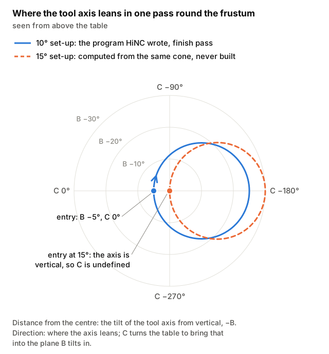
- Risk. On an orthogonal B/C table, 15° of tilt plus the cone's 15° half-angle makes the tool axis exactly vertical at the entry point, where the C axis is undefined and can swing half a turn.
- How it was noticed. Working out the tool axis in table coordinates before writing the CL.
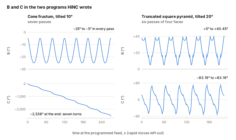
- Resolution. 10°: the tool axis stays 5° to 25° off vertical and C turns one smooth revolution per pass.
- Evidence it held. The program HiNC wrote keeps B between −25° and −5° and winds C steadily, with no half-turn anywhere.
Where to put program zero
- Situation. The part sits tilted; program zero could tilt with it.
- Risk. HiNC's machine play uses program zero's full position and orientation, while a replayed NC program uses only the work offset's translation. A tilted program zero would make the two cut in different places, without a message.
- How it was noticed. Reading how HiNC maps a CL onto the machine before building the project.
- Resolution. The tilt is built into the meshes and the toolpath; program zero stays parallel to the table, and the project needs translations only.
- Evidence it held. The machine play and the program replay agree in cutting-depth peak to 0.00001 mm.
Holder and stick-out
- Situation. The paper gives neither.
- Risk. Too long is unrealistic; too short and the holder strikes the blank.
- How it was noticed. The tool is tilted, so the usual check “deepest cut plus stick-out above the stock” does not apply.
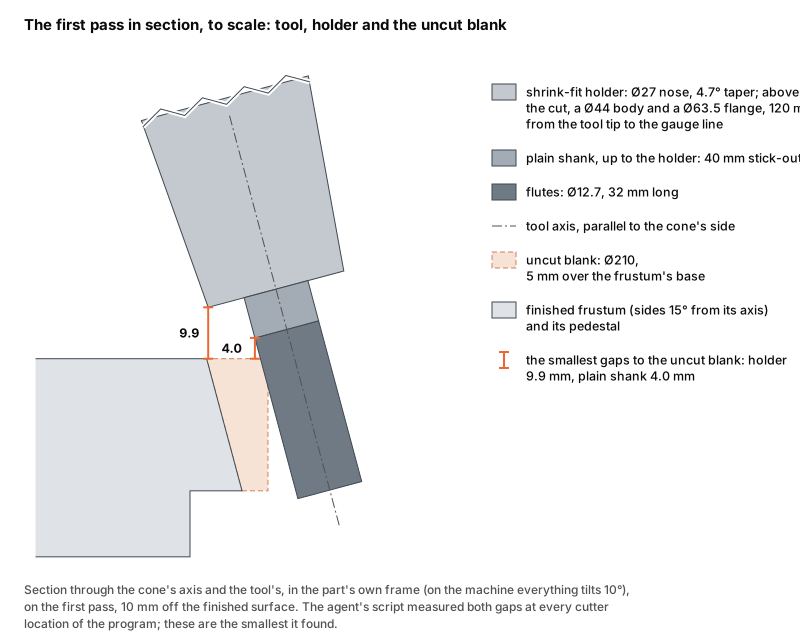
- Resolution. A shrink-fit holder with a Ø27 mm nose and 40 mm stick-out — the flute length plus 5 mm, rounded up — and a clearance check at every cutter location in the script (Cutter Geometry).
- Evidence it held. The holder keeps 9.9 mm from the uncut blank on the frustum and 11.7 mm on the pyramid; the plain shank never touches it.
Which five-axis machine?
- Situation. The case needs a five-axis B/C machine. The generic chain in HiNC's library is a three-axis one, and the case does not use the library's five-axis models: the cut depends on the kinematics, not on any particular machine's looks.
- Risk. Two agents each building their own generic machine would double the work and diverge.
- How it was noticed. Another agent, working on a case that also needed a B/C machine, asked whether one was being built.
- Resolution. One generic B/C machine of plain boxes and cylinders, built by that agent to this case's needs: a tilt range beyond ±60°, an endless C axis, a table over 300 mm, real kinematics (Building Virtual Machine Tools).
- Evidence it held. Both cases ran on it; its roles bound every axis with no warning.
3,436 collisions between the cradle and the spindle head
- Situation. The first play on the machine reported the head hitting the tilting cradle.
- Risk. It looked like a toolpath problem; changing the toolpath would have been the wrong fix.
- How it was noticed. The agent computed the machine's pose at every cutter location with its own kinematic model: its predicted collisions covered the same span of the toolpath as HiNC's — from line 96 to line 3713 against HiNC's 96 to 3714, the engine counting the move into the next point. With the part 50 mm off the table's axis and tilted, the cutting point swings 126 mm out along Y; the spindle nose reaches 80 mm further, into the cradle's side wall at 200 mm.
- Resolution. The machine's builder moved the side walls out to 260 mm.
- Evidence it held. The agent's model predicted no interference for either part, and every replay afterwards reported no collision.
Home was inside the part
- Situation. The machine's home put the spindle only 100 mm above the table, and the program HiNC writes starts with a return to home.
- Risk. With a 120 mm tool, that return would put the tool tip 20 mm below the table top.
- How it was noticed. Reading the machine's home position against the tool length before the first replay of the written program.
- Resolution. Home and tool-change height set to 600 mm.
- Evidence it held. The replay's only extra motion is that climb and the tool change, with no collision.
The work offset read too early
- Situation. Setting the work offset right after loading the machine gave a nonsense value.
- Risk. A replay cut in the wrong place, or not at all.
- How it was noticed. The value was nowhere near the one computed from the set-up.
- Resolution. Measured before the reset, while the last play's session was still open, the endpoint still saw the set-up from before the machine was loaded: the run's copy of the equipment is refreshed at the reset. The measurement itself sets every axis to zero, so the last run's angles were not the cause. The offset is set after every reset and before the start.
- Evidence it held. Every later read gave the computed value, (50, 0, −55.742) for the frustum.
One stock cache for every project in a folder
- Situation. HiNC can cache the meshed blank in a file, and the default file name is shared by every project in a folder — here four projects, two parts.
- Risk. The pyramid's project starting from the frustum's blank.
- How it was noticed. Planning the second project in the same folder, before it ran.
- Resolution. One cache file per set-up.
- Evidence it held. Each set-up's two projects named and read that set-up's own file; neither part ever read the other's blank.
After a rebuild the coarse numbers moved
- Situation. After a rebuild the 1 mm cutting-depth peaks changed — the frustum's from 27.319 to 27.227 mm, the pyramid's from 23.140 to 23.239 mm — while the 0.25 mm values stayed the same to the published digits.
- Risk. Publishing a number that no fresh build reproduces.
- How it was noticed. Only the coarse numbers moved, and the play reported reading a cached mesh instead of writing one.
- Resolution. The cache outlives the project and had been read at the wrong resolution; it is deleted before a rebuild or a change of resolution.
- Evidence it held. With a fresh stock mesh the values came back: the pyramid's in the blind build, the frustum's 27.319 mm when its toolpath played on the machine-independent device on HiNC 3.2.40.
The toolpath play and the written program differ — is that an error?
- Situation. The step counts and times differ: 39 more steps and 0.36 s on the frustum's program, 144 fewer steps and 0.95 s less on the pyramid's.
- Risk. Mistaking a difference in rapid moves for a post-processing error, or the reverse.
- How it was noticed. Comparing the two plays side by side.
- Resolution. The toolpath play times a rapid at its own 20,000 mm/min, the program's
G00at the controller's per-axis rapid rates; the program also climbs to home and steps through a tool change, where the toolpath play loads the tool at once. - Evidence it held. The cutting-depth peaks agree to 0.00001 mm, and converting the pyramid's toolpath a second time produced the same program byte for byte.
Is the instruction enough for someone else?
- Situation. The build was recorded as an instruction.
- Risk. An instruction only its author can follow.
- How it was noticed. By testing it: a separate agent received only the shared build guide and a copy of the case folder.
- Resolution. It built the pyramid's projects and matched every 1 mm number of the instruction; the four unclear points it reported were fixed.
- Evidence it held. The program HiNC wrote in its build was identical byte for byte to the one HiNC wrote in the agent's.
The server crashed when the picture was taken
- Situation. The first attempt to open the 3D view for the picture stopped the server process; it restarted by itself with the project closed, and the picture came out empty.
- Risk. Taking down a server other agents share, and publishing an empty picture.
- How it was noticed. The picture showed a blank background with a 0.3 mm scale bar, and the server reported no project open; its log showed two views starting at once, four graphics allocation failures in a row, then the crash.
- Resolution. The agent recorded the finished part, replayed only a short pose program that re-traces the finish pass so the tool stands in the cut, and opened a single 3D view.
- Evidence it held. The server did not restart again, and the two HiNC pictures on this page came from that session. The cause of the first crash was not established.
Results and benefits
Everything here is simulated; nothing was cut on a real machine. Measured on HiNC 3.2.39.
| Measured | Cone frustum | Pyramid |
|---|---|---|
| Steps, toolpath on the machine / written program | 36,981 / 37,020 | 29,786 / 29,642 |
| Cutting-depth peak at 1 mm / 0.25 mm | 27.319 / 26.936 mm | 23.140 / 22.892 mm |
| Simulated cycle time, toolpath / program | 271.90 / 272.27 s | 226.26 / 225.31 s |
| Rotary axes in the written program | B −25° to −5°, C winds seven turns, to −2,538° | B +5° to +40.45°, C about ±83° (−83.19° to +83.19°) |
| Lines executed, toolpath / written program — every line of each file | 5,352 / 5,333 | 4,259 / 4,189 |
| Holder clearance to the uncut blank — derived by the agent's script, not measured by HiNC | 9.9 mm | 11.7 mm |
| Plain shank clearance to the uncut blank — derived likewise | 4.0 mm | 7.3 mm |
| Tool's lowest point against the wedge's top plane, in part coordinates — derived likewise | Z −1.5 against Z −12.7 mm | Z −2.34 against Z −15 mm |
| Cutter to the finished surface, closest — derived likewise | 0 mm: it touches, never enters | 0 mm |
Every acceptance play on the machine touched the stock, built the geometry difference and ended with no warning and no error, and each toolpath's play on the machine wrote one program. On the machine-independent device, on HiNC 3.2.40, both toolpaths played at 1 mm with no warning and gave the machine play's cutting-depth peak: 27.31894 against 27.31896 mm on the frustum, 23.140 mm on the pyramid. The cutting-depth peak is the length of the flank in contact along the tool axis — from the tool's bottom, 1.5 mm below the part's edge, up to the blank's top face — not a radial depth; the finer resolution follows the blank's edge more closely, so its peak is lower.
What the plays cost on the 32-thread server:
| Cone frustum | Pyramid | |
|---|---|---|
| A 1 mm play | 20 to 35 s | 5 to 25 s |
| A 0.25 mm play, toolpath / program | about 290 / 260 s | about 140 / 150 s |
| Stock mesh recorded at 0.25 mm | 177 MB | 8.5 MB |
| Server's resident memory, the program replayed at 0.25 mm on HiNC 3.2.41 | up about 1.7 GiB, from 4.9 to 6.6 GiB, over 216 s; at most 6.8 GiB in the half minute after the play | not recorded |
- For a machining engineer. Five-axis side milling of analytic surfaces can be done without a
five-axis CAM: an agent writes the cutter locations, and HiNC turns them into a
G43.4program that carries B and C wherever the tool axis changes. Before any metal is cut, the simulation caught a cradle too narrow for the head; the work offset HiNC read back did not match the one worked out from the set-up, which led the agent to find that it must be read after the reset; reading the machine's home against the tool length, the agent caught a home position that would have driven the tool into the part; and the agent's own script checked the holder's clearance. - For a teacher or a student. Reading a drawing that carries bare numbers; a real kinematic singularity and how the choice of tilt avoids it; why program zero should stay parallel to the table when HiNC writes the NC from a toolpath; and that a clean message list is not proof — two independent paths are.
- For someone weighing the approach. On a 32-thread server each 1 mm play took 5 to 35 s and each 0.25 mm play 140 to 290 s; the heaviest, the frustum's program at 0.25 mm on 3.2.41, raised the server process's resident memory by about 1.7 GiB. The toolpath script is some 500 lines of Python with one numerical library. Most of the effort went into the dilemmas above, not into the toolpath.
Honest limits
- Assumed, not measured. The flute count and length, the holder, the alloy and the shapes of the blank and the fixture are the agent's choices. The machine is a generic block model with generic travel, not the paper's machine: it answers geometric questions — reach, rotary range, interference — not dynamic ones.
- Demonstration toolpaths. The toolpath comes from a short script, not a commercial CAM; it does not optimise engagement or smooth the tool axis beyond what the surfaces give.
- Holder clearance is the agent's own check. The holder's 9.9 / 11.7 mm and the plain shank's 4.0 / 7.3 mm to the uncut blank come from the script's check at every cutter location; that check, not the plays' collision lists, is the evidence for them. HiNC's collision check reports whether anything interferes, not how much clearance is left, so only the script checks the 5 mm margin.
- Not checked by the engine. Writing the NC from a cutter-location play, HiNC gives no message when a tilted program zero would make the written program cut elsewhere than the machine play (see the dilemma Where to put program zero).
- The crash when the picture was taken. When two 3D views started at once for the picture, the server process stopped once; the cause was not established. With a single 3D view open it did not happen again (see the dilemma The server crashed when the picture was taken).
- Not built. The 15° frustum set-up.
What a reader can take to their own case
- Write down what a passing run must show before the run, and read the message list, not only the status.
- Play one program two independent ways and compare them; agreement is the evidence.
- When a collision appears, model the machine yourself before changing the toolpath.
- Check what HiNC reports against what you compute yourself: the work offset against the value the set-up gives, the collision span against your own kinematic model.
- When HiNC is to write the NC from a cutter-location file, keep program zero parallel to the table: its machine play uses program zero's full orientation, the replayed NC only the work offset's translation.
- When only the coarse numbers move, suspect a cached input.
Source and licence
- Source. S. Moylan, D. Blumenfeld, M. McGlauflin, R. Fesperman, M. A. Donmez, Evaluation of
Proposed Test Artifacts for Five-Axis Machine Tools, Proceedings of the ASPE 2011 Annual Meeting,
vol. 52, pp. 520–523 — https://tsapps.nist.gov/publication/get_pdf.cfm?pub_id=909384. If the
link moves, search for
Moylan "Evaluation of proposed test artifacts for five-axis machine tools"orNIST cone frustum truncated square pyramid five-axis. The copy this case used, downloaded from that link on 2026-09-27 and found unchanged there on 2026-09-29, has the SHA-256a184d1c8a538318b418c6564e3a525dc433f3c42eed38bbf0a29b9ace0c4b266. - Licence. An official contribution of the National Institute of Standards and Technology (NIST), not subject to copyright in the United States — the paper's own footnote; see NIST's copyright statement.
- Attribution. Artifact dimensions and cutting conditions after Moylan et al., National Institute of Standards and Technology (NIST), ASPE 2011. NIST does not endorse this case, HiNC or any product used here; the material is provided as is, without warranty.
- What was changed. Of the paper, only its Figure 1 — the two drawings — is reproduced here, cropped from the PDF without its caption; everything else taken from it is numbers. The models, blanks, fixtures and toolpaths were made for this case from the paper's drawings and conditions; the machine and the holder are generic ones the paper does not describe. The charts and the section are drawn from the programs HiNC wrote and from the agent's script. The reader fetches the paper from NIST.
See Also
- Showcase — the other cases and how a case page reads
- Cutter-Location Playback — playing a CL file, and converting it to NC
- Project Construction — the build order the agent followed
- Replay Acceptance over the HTTP API — the evidence a run is accepted on
- Cutter Geometry — holder profile, stick-out and tool length
- Building Virtual Machine Tools — a machine with no model