THWS Keychain: A Siemens 840D sl Program with No Model, No Stock and No Fixture
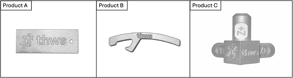
A university in Germany published the programs it ran on a five-axis Spinner U5-620 with a Siemens 840D sl control, as part of an open data set on machine changeovers. The shortest of the three engraves a keychain: a metal plate with the THWS logo and the word “thws” traced by a 90° chamfer mill, and a hole drilled at one end for the ring. For this part the data set gives the NC program, a tool list, a photo and the machine's one-second records of each run, but no CAD model, stock, fixture or holder.
An AI agent took that program and, through the HiNC web API, built a simulation that cuts the keychain as the program commands it, replayed it until every message was accounted for, had a second agent rebuild it blind, and then used it to find where the cycle goes: 13 of its 28.7 simulated seconds (45 %) are the tool moving up and down 16 mm at cutting feed between the contours, and a 2 mm clearance would take 10.5 s off the part with the cut unchanged. Everything on this page is simulated; nothing was cut on a real machine.
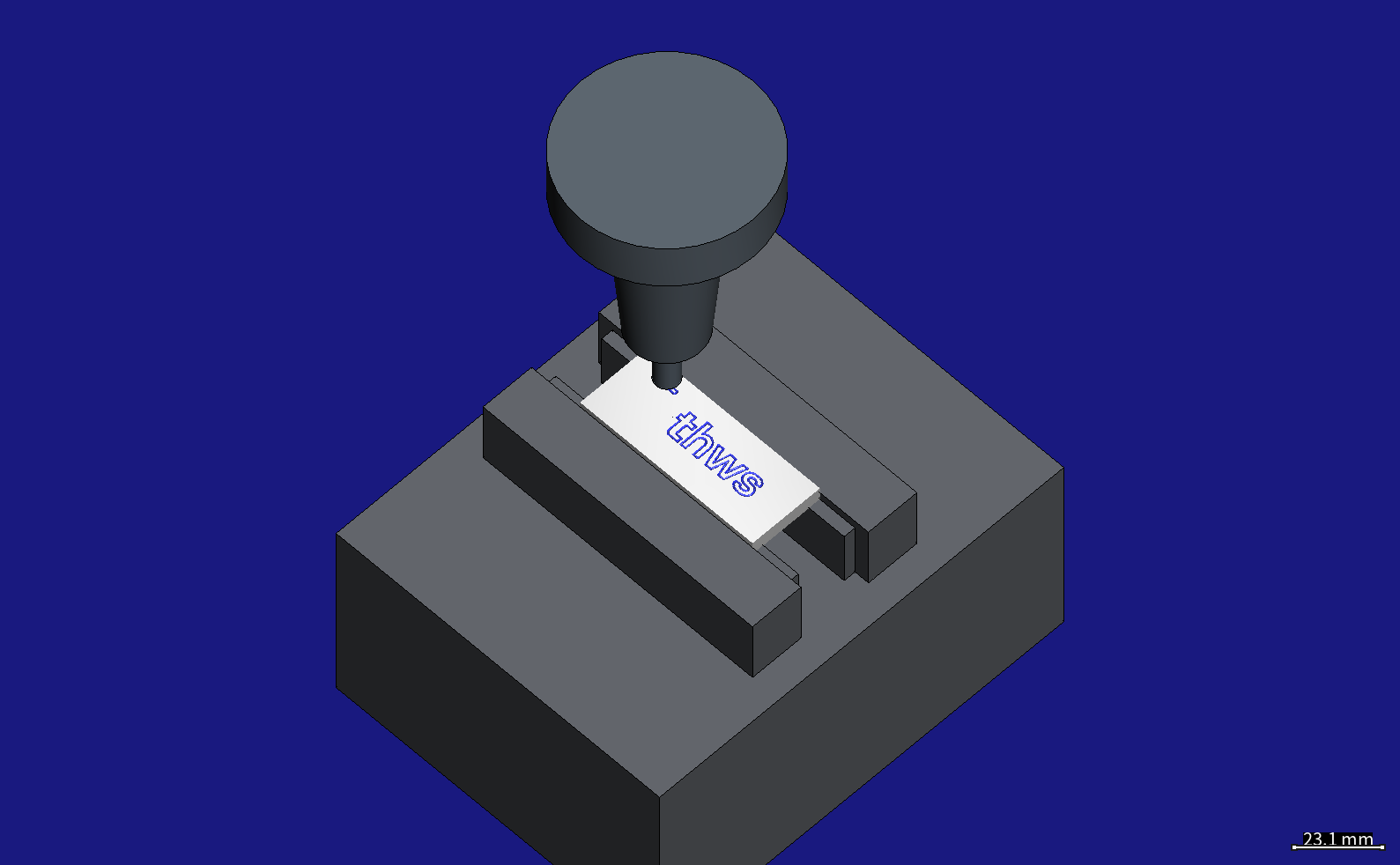
The case
| Given | Missing |
|---|---|
Keychain_Schluesselanhaenger.mpf, 644 lines of Siemens 840D sl code: two engraving operations with a 90° chamfer mill (ENTFRAESER_D8_N_90GRAD), one drilling operation with a Ø3.3 drill (BOHRER_D3.3_VHM) |
A model of the part, so there is no geometric difference to check against |
| A tool list naming each tool's manufacturer and order code; the tool maker's data sheets are public | Stock size and placement, material, fixture, holders, stick-outs, tool lengths |
| The machine's name and control, the data descriptor's photo of the finished keychain, and the machine's one-second records (the data descriptor counts an average of 83 records per production run of this part, interruptions included) | The work offset, the machine's coordinates and travel, what the original machine's own M-codes do |
The program uses the dialect a Siemens user meets every day: DEF REAL variables, SUPA moves in
machine coordinates, CYCLE800() to cancel a swivel, CYCLE832 for high-speed settings,
MCALL CYCLE81 for drilling, tools called by name (T="…") with edge D1, and B and C words for
the rotary axes, which only ever go to 0.
What the agent built
Each value is marked read (stated by the source), derived (worked out from the source), chosen (the agent's choice where the source says nothing) or measured (read back from HiNC, with the version).
| Item | Value | Basis |
|---|---|---|
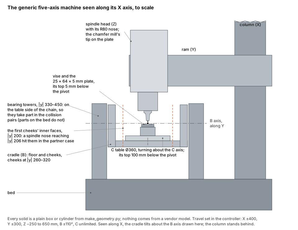
| Machine | A generic five-axis machine written by a script from plain boxes and cylinders: head-side X, Y, Z; a cradle tilting about Y (B) carrying a Ø360 rotary table (C); travel X ±400 mm, Y ±300 mm, Z -250 to 650 mm, B ±110°, C unlimited | Chosen. The program commands B and C, so the machine must have them, and HiNC's library has no five-axis machine cleared for publication. The travel and the table size were chosen with a five-axis case of this series, which needed B beyond ±60° and a table of at least Ø300. |
| Fixture | A generic machine vise: the plate on two parallels, centred on the vise, its bottom face 90 mm above the vise's base, the jaws gripping its 25 mm width and standing 2 mm below its top | Chosen. The drill goes through the plate, so the hole needs air below it; the chamfer mill must never reach the jaws. |
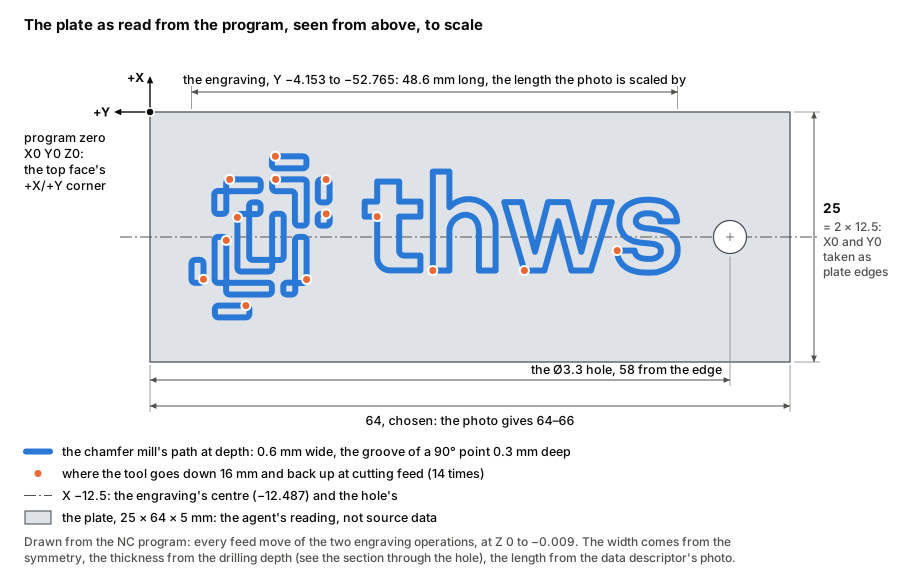
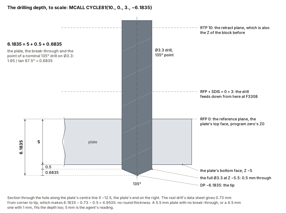
| Stock | A 25 × 64 × 5 mm box | Derived, with one choice. The drilling cycle's depth DP = -6.1835 reads as 5 + 0.6835 + 0.5: a 5 mm plate, the height of a nominal 135° point on Ø3.3 (1.65 / tan 67.5°) and 0.5 mm break-through. The engraving and the hole are centred on X ≈ -12.5; taking X0 and Y0 as plate edges, as a CAM work zero usually is, the plate is 25 mm wide (the photo, scaled by the 48.6 mm length of the engraving, shows about 25.7). The photo gives 64-66 mm for the length; chosen: 64. |
| Target model | None | Read. The source has no model, so there is no geometric difference to check; the acceptance rests on the cut itself. |
| Program zero | The top face's +X/+Y corner; G54 = (12.5, 32, -5) on this machine | Derived (the drilling cycle's reference plane is Z0; the engraving and the hole lie at negative X and Y); the G54 value measured by HiNC 3.2.39 from the model. |
| Controller | Siemens; tool numbers 1 and 2 mapped to the program's tool names; the $TC_DP offset rows; the original machine's M27, M29, M50, M51, M65 declared; home and tool-change height Z610 |
Read: the brand and the codes the program uses. Chosen: the tool numbers. Derived: how each item is set up (see the dilemmas). |
| Material | Aluminium; 6061-T6 from the material library | Derived that it is aluminium: the photo shows a bright plate, and the drill's S23632 is 245 m/min on Ø3.3 – the tool maker's value for short-chipping aluminium. Chosen: 6061-T6 as a stand-in. |
| Chamfer mill | Cone profile Ø8, 45° to the horizontal, 4 mm cutting length, pointed, 4 flutes, 63 mm long; 0° helix, 0° rake, 10° relief; stick-out 27 mm in a shrink-fit chuck (Ø24 nose, 80 mm gauge length) | Read from the tool maker's data sheet: diameter, profile angle, cutting length, length, flutes, the 27 mm projection. Derived: that it is pointed (a 4 mm cutting length is D/2 at 45°). Chosen: the chuck, the helix angle (the sheet says only “special helix angle”), and the rake and relief angles. |
| Drill | Cone profile Ø3.3 with a 135° point, 20 mm flutes, 2 edges, Ø6 × 36 mm shank, 62 mm long; 30° helix, 0° rake, 10° relief; stick-out 26 mm in the Ø6 chuck | Read from the data sheet, including the 26 mm projection. Chosen: the chuck, the helix angle, and the rake and relief angles. |
| Tool lengths | 107 and 106 mm (holder gauge length 80 plus the stick-out) | Derived. |
| Engraving depth | -0.3 mm length wear on the chamfer mill's offset row | Chosen; see “The engraving only grazed the plate”. |
| Spindle | A generic 24,000 rpm motor spindle, 7.5 kW continuous | Chosen. The program runs at up to 23,632 rpm; the source names no spindle. |
| Mission | The program as published; collision detection on; 1 mm for a first run, 0.0625 mm for acceptance | Chosen. The engraved lines are only 0.6 mm wide. |
The two tools as entered in HiNC; the program calls them by name, and the tool numbers are the agent's:
| T1 | T2 | |
|---|---|---|
| Name in the program | ENTFRAESER_D8_N_90GRAD |
BOHRER_D3.3_VHM |
| Real tool, from the tool list and the data sheet | Garant 208110 8, solid-carbide 90° chamfer mill, 63 mm long | Garant 122380 3,3, solid-carbide drill, 62 mm long |
| Profile | cone, Ø8, 45° to the horizontal, 4 mm cutting length | cone, Ø3.3, 22.5° to the horizontal (a 135° point), 20 mm flutes |
| Flutes, helix, radial rake, radial relief | 4, 0°, 0°, 10° | 2, 30°, 0°, 10° |
| Shank, from the tip | Ø8 from 4 to 63 mm | Ø3.3 to 23 mm, widening to Ø6 at 26 mm, Ø6 to 62 mm |
| Holder: shrink-fit chuck, radius at a height above its nose | R12 at 0 rising to R16.5 at 55 mm, then R22 to 63 mm and R31.75 to the gauge line at 80 mm | R10.5 at 0 rising to R15 at 55 mm, then as T1 |
| Stick-out; tool length | 27 mm; 107 mm | 26 mm; 106 mm |
| Cutter material | tungsten carbide, 10 % cobalt, 600 nm grain, from HiNC's library | the same |
How the agent managed the work
- Pass criteria before the run. Before touching the server the agent read the program block by block and wrote down what a correct run must show: which blocks cut and where, how deep the drill goes, where program zero lands, and which words would raise a message. Every run was checked against those, and the numbers of the first clean run became the reference for all later ones – not “it finished”.
- Everything through the web API, every write read back. The agent built the project with the same routes the HiNC web page uses, read each value back after writing it, saved, reloaded and read them again.
- Coarse, then fine. A 1 mm run checked the set-up in seconds; only then the 0.0625 mm run.
- Research delegated, decisions kept. Two helper agents read the HiNC source and documentation in parallel – one for the machine-file format, one for the API calls and for how the simulator treats each Siemens word in the program – while the agent derived the stock.
- A shared server. One HiNC instance holds one project at a time, and several agents were building other cases of this series on the same server. The agent announced which instance it would use, checked that no run was in progress before each reset, discarded its in-memory experiments by reloading, deleted its temporary files, and closed the project when it was done. It shared the five-axis machine it had written with the agent that needed one, which found the machine's first flaw (the second dilemma).
- A blind build. When its own build passed, the agent handed a second agent nothing but its written instruction and the input files. That agent built the project from scratch and got the same step count, depths, time and messages; its project differed only in randomly generated identifiers and in the wording of free-text notes.
- Adversarial review. Three more agents were asked to find everything wrong: two in the source notes and the instruction, one in this page. Their findings are among the dilemmas below, including three errors of the agent's own.
- Where a person stepped in. The instance required a login the agent did not have; rather than read the server's configuration, it asked the owner, who gave it. The owner's standing rules shaped the build: nothing from a client or of unclear licence (hence the agent's own machine), every tool in a holder a shop would use (hence the chucks and the catalogue stick-outs), and each case's project kept in its own folder. The owner approved closing the finished task. When the owner later changed the purpose of the series from training kits to this record of the agent's work, the agent added the time study and the clearance experiment, to show the simulation helping rather than only replaying.
The dilemmas
Every number below was measured on HiNC 3.2.41 at 0.0625 mm unless another version is named.
The program assumes a machine the library does not have
- Situation. The program moves B and C (
G0 B0.0 C0.0,SUPA … B=_B_HOME C=_C_HOME); the only generic machine in HiNC's library has three axes. - Risk. On a three-axis machine every B and C word is left unconsumed (
Parsing--Unconsumed), and the replay can never be clean. - How it was noticed. Reading the program before building anything.
- Resolution. A generic machine written by a script: head-side X, Y, Z; a cradle tilting about Y (B) carrying a rotary table (C); both rotary axes pointing negative in the chain, so that B+ and C+ are the ISO positive directions of the tool relative to the part.
- Evidence. HiNC bound B and C as rotary axes on its own, and no replay raised
Parsing--Unconsumed.
The cradle was too narrow
- Situation. The keychain only uses B0 C0, but the agent that used the machine for a real
five-axis part (a cone tilted 10°, 50 mm off the C axis) got 3,436
Collided(B,Z)messages on HiNC 3.2.39. - Risk. A machine that looks fine on a three-axis job is wrong for the job it was also meant for.
- How it was noticed. That agent computed the colliding span from the machine's kinematics: it covered the same stretch as the engine's report (lines 96 to 3713 against the engine's 96 to 3714; the engine counts the move to the next point in the next sentence), so it was a real clash. The spindle nose (radius 80 mm) reached |y| = 206 mm, and the cradle's side plates started at |y| = 200.
- Resolution. The side plates moved out to |y| 260-320 mm and the bearing towers to 330-450 mm.
- Evidence. The partner case replayed every point of both its parts on the widened machine with no collision.
Some machine parts never collide
- Situation. HiNC generates collision pairs by walking the machine's chain from the ground to the
tool and to the table, and drops the ground
Oand the basebasefrom both walks by name, so a part attached tobaseis never paired. - Risk. The trunnion bearing towers – what the spindle head is most likely to hit when the cradle tilts – would have been drawn but never checked.
- How it was noticed. Reading the machine-tool documentation before writing the chain.
- Resolution. The towers hang on their own element on the table side of the chain.
- Evidence. The partner case's collision was reported against the cradle, a part on the same side of the chain.
Saving the project rewrote the machine file
- Situation. After the first save, the machine file the project had loaded came back different: HiNC writes the role bindings out as elements, adds a byte-order mark and reformats the solids.
- Risk. A file kept as the source of the machine silently changes each time a project using it is saved.
- How it was noticed. The file showed as modified after a save.
- Resolution. The set-up files the agent made stay as they are in their own folder; the build uploads copies into the project and loads those, so a save rewrites only the project's copies.
- Evidence. After every save the machine file in the set-up folder was unchanged; only the project's copy had been rewritten.
The files a reader gets did not carry the machine
- Situation. The case's backup package was set to carry only the source's own files and the notes; the machine and the vise are the agent's work.
- Risk. Nobody could rebuild the case from the package.
- How it was noticed. Checking what the package would contain before handing it to the blind build.
- Resolution. Set-up files the agent made are kept in their own folder and packed with the case.
- Evidence. The blind build used only the package and succeeded.
The build guide's table placement would move the part
- Situation. The series' build guide places the table of its three-axis machine with one translation; this machine already carries its table's placement on the same branch.
- Risk. Following the guide literally overwrites the table's 100 mm drop and moves the whole set-up.
- How it was noticed. Reading the step against the machine's chain.
- Resolution. The instruction for this case skips that step.
- Evidence. G54 came out as (12.5, 32, -5), where the vise geometry puts the plate's corner.
The program's home is another machine's coordinates
- Situation. The program goes home with
SUPA G0 Z=_Z_HOMEandX=_X_HOME Y=_Y_HOME, set to 610, -365 and 224 – the Spinner's machine coordinates. A run starts at machine zero, and a tool change sends Z to the machine's tool-change position, 0 by default. - Risk. At machine zero the spindle nose sits 5 mm above the plate, and a tool change at Z0 would bring the new tool down through it.
- How it was noticed. Comparing the program's home with the machine's own zero before the first run.
- Resolution. Home and tool-change height set to Z610, the program's own home.
- Evidence. Both rows read back 610; no replay raised a collision or a stroke error.
The shortcut for travel covers only X, Y and Z
- Situation. The series' three-axis cases set travel with one call for X, Y and Z; this machine also needs B, and the route that sets one axis takes a signed lower limit.
- Risk. Used here with the series' standard values, made for its three-axis machine, the call sets upper limits of 0 on X, Y and Z, and the program's home Z610 is out of travel.
- How it was noticed. A reviewer read the controller's source for both routes.
- Resolution. Travel set per axis – X, Y, Z and B – with signed limits; C, which turns without end, gets none.
- Evidence. The limits read back as sent, and no replay raised
StrokeLimit--*.
The program calls its tools by name
- Situation.
T="ENTFRAESER_D8_N_90GRAD"andT="BOHRER_D3.3_VHM"; HiNC's tool house is keyed by number. - Risk. Without a mapping the simulator raises
ToolChange--NameUnresolved, changes no tool, cuts nothing – and still reports the run as finished. - How it was noticed. A helper agent found the case in the parser's tests.
- Resolution. A name-to-number table (1 and 2). Acceptance never relies on “finished”.
- Evidence. Both tools cut: the engraving from step 292 to 4,252, the drill from 5,161 to 5,201.
The Siemens offset table is separate
- Situation. A Siemens run reads tool lengths from its own
$TC_DPtable by tool and edge, not from the generic table HiNC fills from the tool house, and the two tables apply a wear with opposite signs. - Risk. Empty rows fall back with a warning; a wear typed with the generic table's sign moves the tool the wrong way.
- How it was noticed. Reading the Siemens offset documentation and the parser.
- Resolution. Rows (1, 1) and (2, 1) written with 107 and 106 mm and read back.
- Evidence. The only offset warning left is for tool 0 (see “A tool offset before the first tool”).
The engraving only grazed the plate
- Situation. The chamfer mill's programmed point stays on the top face (Z 0 to Z -0.009); a pointed 90° tool there only touches the surface.
- Risk. A run that touches the part but engraves no logo – and with no model to compare with, nothing else would say so.
- How it was noticed. The agent asked where the engraving depth came from on the real machine. Not from the program, so from the set-up: the tool data or the work offset, which the data set does not record.
- Resolution. A -0.3 mm length wear on the chamfer mill's
$TC_DProw, as an operator would enter an engraving depth. The depth is an assumption and is labelled as one. - Evidence. With the wear, the engraving's depth peak is 0.3025 mm and its summed chip volume 9.55 mm³; with the wear at 0, the peak is 0.0025 mm and the volume 0, while the drilling is unchanged.
The drill's point is not the data sheet's
- Situation. The plate thickness rests on a nominal 135° point, 0.6835 mm high; the drill's data sheet gives 0.73 mm from corner to tip.
- Risk. Stating the nominal value as the real drill's is wrong, and a thickness read from it could be off.
- How it was noticed. A reviewer compared the source notes with the data sheet.
- Resolution. The notes now say the program's author evidently used the nominal cone: only that value makes 6.1835 a round 5 + 0.5; the model uses the same cone.
- Evidence. 5 + 0.6835 + 0.5 = 6.1835 exactly; with 0.73 no round thickness fits.
Five M-codes of the original machine
- Situation.
M50at the start,M27,M29,M51,M65at the end. The program's comment names three: “Spuelung Spaenefoerderer Absaugung” – flushing, chip conveyor, extraction. - Risk. Each undeclared code raises
Parsing--Unconsumed; editing them out would hide what the program really does. - How it was noticed. A helper agent's audit of every word in the program.
- Resolution. Each is declared as a machine function that moves nothing, with a note. The program is played as published.
- Evidence. Five
DeclaredMCode--UnmodeledEffectsmessages, atN80,N6400andN6410, and noParsing--Unconsumed.
A tool offset before the first tool
- Situation. Block
N190,SUPA G0 X=_X_HOME Y=_Y_HOME B=_B_HOME C=_C_HOME D1, selects edge D1 before the program has called any tool. - Risk. A warning that could be mistaken for a set-up error – or “fixed” by editing the program.
- How it was noticed. It was the one warning left:
SiemensToolOffset--TcdpRowMissingfor (T0, D1). - Resolution. Left as it is and explained: the program ends with
T0/M6, so presumably the real spindle is empty when it starts again too, and the block moves in machine coordinates and cuts nothing. - Evidence. Exactly this one warning in every run, the blind build's included.
SUPA leaves out the tool length in HiNC
- Situation. HiNC treats
SUPAlikeG53: the block positions the spindle's gauge line in machine coordinates, without frames and without the tool length. - Risk. A program that expects the tool length to stay active through
SUPAwould land elsewhere. Whether the 840D sl keeps it the agent did not verify. - How it was noticed. A helper agent's audit of the parser.
- Resolution. Checked the program: every
SUPAblock that moves Z also deselects the offset withD0(N180,N250,N6100,N6240,N6360), so both readings give the same move. The Siemens section of the NC dialect documentation describes the behaviour. - Evidence. The five
SUPAZ moves all carryD0in the program, and the replay raised no stroke or collision message at any of them.
MCALL retracts to the block before
- Situation.
MCALL CYCLE81(10.,0.,3.,-6.1835)names a retract plane (RTP) of 10; HiNC returns to the Z of the block before the drilling position instead. - Risk. A program whose previous Z differs from its RTP would retract to a different height.
- How it was noticed. The parser audit.
- Resolution. Here the block before (
N6300) parks at Z10, the same as RTP, so nothing changes. - Evidence. In the program the retract plane and the previous block's Z are both 10.
T0 / M6 leaves the last tool in the spindle
- Situation. On a real machine the program's closing
T0andM6put the drill away; in HiNC a change to tool 0 does nothing. - Risk. Any move after it would drag a tool the real machine no longer holds.
- How it was noticed. The parser audit.
- Resolution. Here it is the last block before
M30, so it does not matter; the NC dialect documentation describes the behaviour. - Evidence. No move follows it.
The guide's stick-out rule and a tool of fixed length
- Situation. The series' build guide sizes the stick-out as the longer of the flute length and the deepest cut, plus 5 mm, rounded up to 5 mm: 10 mm for the chamfer mill, 25 mm for the drill.
- Risk. A 63 mm chamfer mill with 10 mm showing would need 53 mm of its shank in the chuck.
- How it was noticed. Comparing the rule's number with the tool's own length.
- Resolution. The catalogue projections: 27 mm (leaving 36 mm of shank to clamp) and 26 mm (the drill's whole 36 mm shank clamped), with the reason written next to them. The agent also added to the build guide that when a tool's own length forces a longer stick-out, the value is stated with its reason.
- Evidence. Computed from the tool lengths and the program: the holder nose is 26.7 mm (chamfer mill) and 19.8 mm (drill) above the stock at the deepest point.
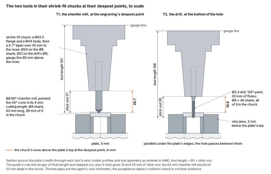
The holder checks of the series' build guide, for both tools:
| Check | T1, chamfer mill | T2, drill |
|---|---|---|
| Chuck nose radius against the cutter's radius | 12 > 4 mm | 10.5 > 1.65 mm |
| Stick-out against flute length | 27 ≥ 4 mm | 26 ≥ 20 mm |
| Deepest point; the chuck nose there | Z -0.31 (Z -0.009 programmed, 0.3 mm wear); Z +26.7 | Z -6.18; Z +19.8 |
| The guide's stick-out rule; the stick-out used | max(4, 0.31) + 5 → 10 mm; 27 mm | max(20, 6.18) + 5 → 25 mm; 26 mm |
| Tool length | 107 = 80 + 27 mm | 106 = 80 + 26 mm |
Collision--Detected in the acceptance replay |
none | none |
Program zero read before a reset was wrong
- Situation. The route that computes G54 from the model answered with a wrong value right after the fixture and the part were placed.
- Risk. The whole program runs in the wrong place.
- How it was noticed. The partner case read (-62.7, 65.2, -134.9) before a reset and the expected (50, 0, -55.742) after it.
- Resolution. Reset first, then compute: a reset is the boundary at which the running copy of the set-up picks up edits made during a session.
- Evidence. G54 = (12.5, 32, -5) in this build and in the blind build, and the engraving lands on the plate.
The shared spindle file changed on the first save
- Situation. The spindle description the series uses is rewritten by HiNC in a newer schema at the first save (2,495 bytes become 3,111).
- Risk. A check that compares the project's copy with the original fails for no fault.
- How it was noticed. The blind build compared file sizes after saving.
- Resolution. Uploads are compared when they are made, not after a save.
- Evidence. Every upload's length matched the local file; reloads reported no messages.
A message that appears only once
- Situation. The collision-preparation pair of messages (
Collision-Prepare--Startand--Done) appears only when collision detection is switched from off to on: on the first replay of a newly created project, or the first after loading a project saved with detection off. This project is saved with detection on, so after a load or a reload the pair does not appear. - Risk. An acceptance that counts every message by id reads the same run as clean one time and not the next.
- How it was noticed. The blind build saw it on its coarse run but not on its fine one.
- Resolution. The expected list names the pair as one that may appear, not as a fault.
- Evidence. Every run since matched the list.
More steps than the rule of thumb
- Situation. The replay has 5,930 steps; “cutting time × spindle speed” predicts about 3,800.
- Risk. A memory estimate built on the rule is low.
- How it was noticed. The blind build's report.
- Resolution. Moves between cuts with the spindle running are simulated as steps too; the agent changed the build guide to estimate from all the time the spindle turns.
- Evidence. The blind build reproduced 5,930 steps.
A picture of the holder
- Situation. Selecting a step does not move the drawn tool to it, and the replay page draws no tool by default.
- Risk. A picture without the holder – which this series does not accept.
- How it was noticed. The first pictures showed the vise and the plate, and the tool parked at the program's home.
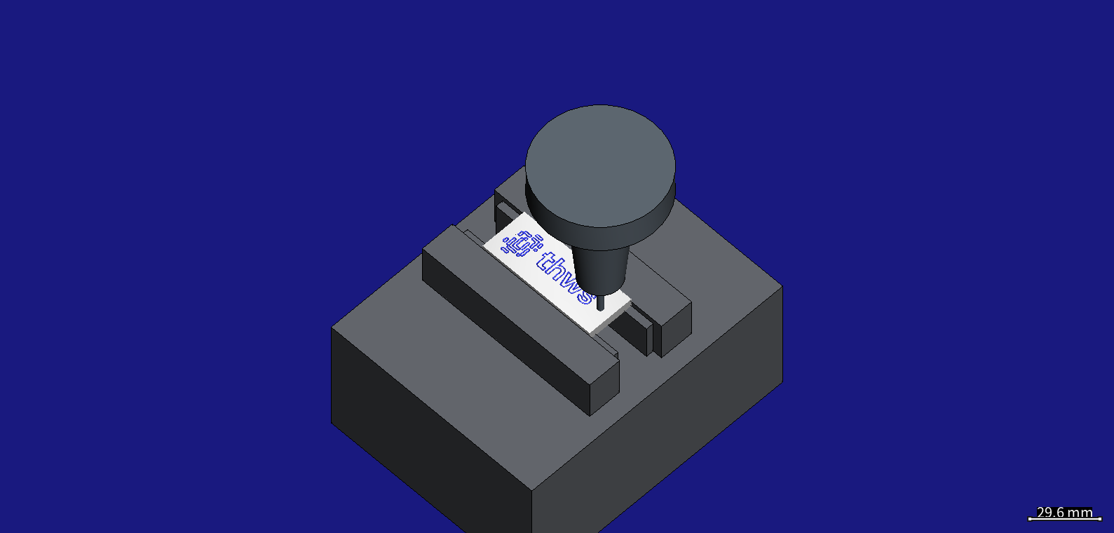
- Resolution. Tool drawing switched on, and the replay paused mid-cut: during the engraving, and stepped block by block into the drilling.
- Evidence. The two HiNC pictures on this page.
Reading removed volume
- Situation. The per-step chip volume summed over the run is about a third of the grooves' geometric volume and half of the hole's; what exactly it counts was not established.
- Risk. Quoting it as the removed volume would be wrong.
- How it was noticed. Comparing the sums with the grooves' and the hole's geometry.
- Resolution. It is used only to compare runs of the same program, never as an absolute value.
- Evidence. The sums are identical to three decimals between the original and the clearance variant.
The agent's own mistakes
- Situation. Review found three errors in the agent's text: the attribution named the four authors of the paper describing the data set, while the data set and the files are credited to three and two of them; the instruction explained “reset first” with a wrong reason; and the first reading of the photo put 6 mm of plate past the hole, where it shows 7 to 7.5.
- Risk. A licence condition not met; a reader chasing a cause that does not exist; a length stated more precisely than the photo allows.
- How it was noticed. The reviewers compared the attribution with the data set's own record, the explanation with the source code, and re-measured the photo.
- Resolution. All three corrected; the review also moved every inferred value (plate size, material, depth) under an explicit label.
- Evidence. The attribution below matches the data set's record; the length is stated as 64-66 mm with 64 chosen.
Results and benefits
Measured on HiNC 3.2.41 at 0.0625 mm. The simulated cycle counts tool changes as 0 s and has no acceleration.
| Result | Value |
|---|---|
| Steps; program lines executed | 5,930; all 644 |
| Engraving depth, peak | 0.30 mm (the 0.3 mm wear plus the program's 0.009 mm dips) |
| Drilling depth per step, peak | 0.88 mm (the 0.68 mm point plus one revolution's feed, 0.14 mm, to within the 0.0625 mm resolution) |
| Simulated cycle | 28.70 s |
| Tool yield-stress ratio, engraving | 0.6 % |
| Spindle power ratio, engraving | 0.2 % |
| Spindle torque ratio, engraving | 0.08 % |
| Largest cutting-force component, engraving | 19 N (Z); 18 N (Y) |
| Accumulated spindle energy of the cut | 174 J (the same value when the spindle runs 10 s less, so it counts the cut only) |
| Holder nose above the stock at the deepest point (computed) | 26.7 mm (chamfer mill), 19.8 mm (drill) |
| Drilling loads as modelled – not to be used: the drill is simulated as a cone-shaped milling cutter (see “Honest limits”) | axial force 1.6 N, X and Y 0 (a real Ø3.3 drill in aluminium sees on the order of 100 N); thermal yield ratio 0.60 |
| Messages | Sys-Init--FileLines 1, DeclaredMCode--UnmodeledEffects 5, Msg--Display 3 (the program's MSGs), SiemensToolOffset--TcdpRowMissing 1 (explained); no Collision--Detected, no StrokeLimit--* |
The coarse run that checked the set-up and the acceptance run:
| 1 mm, HiNC 3.2.39 | 0.0625 mm, HiNC 3.2.41 | |
|---|---|---|
| Steps | 5,930 | 5,930 |
| Program lines executed | 644 | 644 |
| Stock touched, over the whole run and over the engraving (steps 0-5,000) | yes | yes |
| Engraving depth peak, steps 0-5,000 | 0.29 mm | 0.3025 mm |
| Drilling depth peak per step, steps 5,000-5,930 | 1.61 mm | 0.884 mm |
| Simulated cycle | 28.70 s | 28.70 s |
| A replay on the 32-thread server | about 6 s | about 6 s |
Every message of a replay, with the block that raises it:
| Message | Severity | Count | Where, and why it is expected |
|---|---|---|---|
Sys-Init--FileLines |
Message | 1 | the program file has 644 lines |
DeclaredMCode--UnmodeledEffects |
Message | 5 | M50 (N80), M27 (N6400), M29, M51 and M65 (N6410): the original machine's own functions, declared as moving nothing |
Msg--Display |
Message | 3 | the program's MSG("MILL_FINISH") (N230) and MSG("DRILL_METHOD") (N6220), and one line for the second MILL_FINISH (N2740, “repeated 2x”) |
SiemensToolOffset--TcdpRowMissing |
Warning | 1 | N190: D1 selected before the first tool call, when the spindle is empty (T0); see “A tool offset before the first tool” |
Parsing--Unconsumed, ToolChange--NameUnresolved, StrokeLimit--*, Collision--Detected |
– | 0 | none |
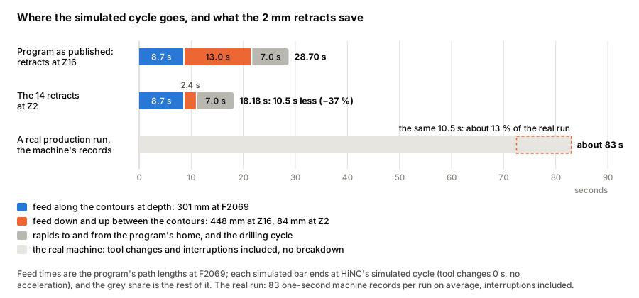
For a machining engineer. The simulation says where the time goes. Of the 28.7 simulated
seconds, 21.7 are feed moves at F2069, and 448 mm of those 749 mm are the tool going down and up
16 mm between the contours at cutting feed – 13 s. The agent replayed a copy of the program with the
14 retracts at Z2 instead of Z16, keeping at Z16 the two approach points that the engraving
operations reach by rapid moves (N330, N2810): 18.18 s, with the same summed chip volume, the
same depth peaks, the same cutting energy and the same messages. If the real clamping stays below
the plate's top, as this vise does, that is 10.5 s saved per part, verified before any machine time
was spent. The machine records suggest about 83 s per real run with its tool changes and
interruptions, so on the machine the saving is nearer 13 % than the simulated 37 %. The mechanical
loads are nowhere near a limit, so for this part the path, not the cut, sets the time. And the
engraving depth is not in the program: it belongs on the set-up sheet.
The clearance experiment in numbers, on HiNC 3.2.41, with the feed paths taken from the program:
| Program as published | The 14 retracts at Z2 | |
|---|---|---|
| Simulated cycle | 28.70 s | 18.18 s: 10.5 s less, -37 % |
| Feed path at F2069 | 749 mm, 21.7 s | 385 mm, 11.2 s |
| of which going down and up between the contours | 448 mm: 14 plunges and 14 retracts of 16 mm | 84 mm: the two plunges after the approaches still 16 mm, the rest 2 mm |
| Depth peak, engraving / drilling | 0.3025 / 0.8842 mm | the same |
| Summed per-step chip volume, engraving / drilling – a comparison value only (see “Reading removed volume”) | 9.550 / 23.356 mm³ | the same to three decimals |
| Accumulated spindle energy | 174 J (4.842 × 10⁻⁵ kWh) | the same |
| Messages | as listed above; no collision | the same |
For a teacher or student. This one short program covers most of what makes a Siemens 840D sl
program different from ISO G-code: variables, machine-coordinate moves, cycles for swivel, smoothing
and drilling, named tools and the $TC_DP table, and machine-specific M-codes. The case also shows
how much can be read out of a program when the model is missing – the plate thickness from a
drilling depth, the width from a symmetry – and where reading stops and an assumption must be
labelled.
For someone weighing the approach. Each replay took about 6 s on a 32-thread server at either resolution; the agent ran about twenty, the experiments and the picture runs included. The run needs roughly 30 MB of step results on top of the service's base of about 1 GB (estimated from the documented rule, not measured). Besides the building agent, seven helper agents took part: three for research, one blind build, three reviews. A person was needed twice: to give the login and to approve closing the task. The errors the reviews found were all corrected before publication.
Honest limits
- The plate's size, its material and the engraving depth are the agent's reading of the program and the photo, not data from the source. A 5.5 mm plate drilled with no break-through, or a 4.5 mm one with 1 mm, fits the drilling depth too.
- The machine is not the Spinner U5-620. Its coordinates differ, only B0 C0 were used, and the real clamping is unknown.
- The drilling's physics is not a drilling model: the drill is simulated as a cone-shaped milling cutter, and its axial force (under 2 N) is far below a real drill's. Its geometry – where and how deep it cuts – is right; its loads should not be used.
- The simulated cycle has no acceleration and counts tool changes as 0 s. The clearance saving was verified in the simulation only; chips, coolant and the real machine's acceleration are not in it.
- The holder's clearance above the plate is the agent's own check: how high the chuck's nose stands at the deepest point is computed from the tool geometry and the program (see “The guide's stick-out rule and a tool of fixed length”); the acceptance replay's collision check is not its evidence.
- Whether the 840D sl keeps the tool length active through
SUPAwas not verified; this program gives the same result either way.
What a reader can take to their own case
- When the model is missing, the program still carries dimensions: a canned cycle's reference plane and depth, symmetric features, a hole's position.
- A path that sits on Z0 with a pointed tool gets its depth from the set-up. Find out where before trusting a clean run.
- For a Siemens program: map the tool names, fill
$TC_DP, declare the machine's own M-codes, take home and tool-change heights from the program'sSUPAmoves, and check everySUPAZ move for aD0. - Take program zero after a reset.
- Read the time breakdown. Feed moves that cut nothing are the cheapest seconds to save, and the simulation can show the cut is unchanged – but weigh the saving against the real cycle, not the simulated one.
- Accept on evidence – steps, what was touched, depths, time, every message by id – never on “finished”.
Source and licence
- Program and tool list: B. Engelmann, A.-M. Schmitt (THWS), https://github.com/ElMoe/Production-Data-Set-for-Five-Axis-CNC-Milling-with-Multiple-Changeovers, external material of B. Engelmann, A.-M. Schmitt, M. Martinez, “Production Data Set for Five-Axis CNC Milling with Multiple Changeovers”, https://doi.org/10.5281/zenodo.15735480.
- Described in M. Martinez, A.-M. Schmitt, A. Schiffler, B. Engelmann, Scientific Data 12, 1067 (2025), https://doi.org/10.1038/s41597-025-05294-0.
- Licence: Creative Commons Attribution 4.0 International, https://creativecommons.org/licenses/by/4.0/, provided as-is without warranties.
- What was changed: the program and the tool list were used unchanged. For the clearance experiment a copy of the program with Z16 changed to Z2 in its 14 retracts was replayed; it is not distributed. The stock, machine, vise, holders and offsets were derived or chosen by the agent. The two pictures with the holder are renders of that simulation; the drawings and the chart are drawn from the program and the agent's set-up files; the photo of the three products is the data descriptor's Fig. 2, © The Author(s) 2025, reproduced unchanged under CC BY 4.0.
- Readers get the files from the original site; this page offers no download. Search keywords if the links fail: “Production Data Set for Five-Axis CNC Milling with Multiple Changeovers”, “Keychain_Schluesselanhaenger.mpf”. The company site keeps a copy of the original files only as a backup in case the original links stop working.
A file fetched from the repository can be checked against the one simulated here by its SHA-256, as the source notes give it:
| File | Path in the repository at commit b800366 | SHA-256 |
|---|---|---|
Keychain_Schluesselanhaenger.mpf |
NC_code/Keychain_Schluesselanhaenger/Keychain_Schluesselanhaenger.mpf |
df1831facaed2c20fb3ab6735d8894bfe01fdf7ffc8412ceefb453f6fda5cb8f |
Tool_information.csv |
Tool_information/Tool_information.csv |
139243c00f0841ac6b10981eaf7c5afbcb3fe6b5d0d981bda4bfd09f43fa63af |
See Also
- Showcase – the other cases in the series
- Project Construction – the build these steps follow
- Replay Acceptance over the HTTP API – the evidence a run is accepted on
- Siemens Tool Offsets – the
$TC_DPtable - Cutter Geometry – holder profile, stick-out and tool length