RPTU Benchmark Parts 4–10: Seven 3-Axis Jobs Set Up and Checked by an AI Agent
An AI agent took seven public test parts — for each, a CAD model, a CAM-posted NC program, a rendering and a line of description — and turned them into HiNC simulation projects through HiNC's web API. It replayed every part twice and let HiNC's results, not its own opinion, decide whether a set-up was right. Along the way HiNC showed where the delivered programs cannot finish the design and where the load is, and confirmed that a shorter tool cuts the same. The agent cut nothing: the data set's authors machined the parts, but none of their results is used here.
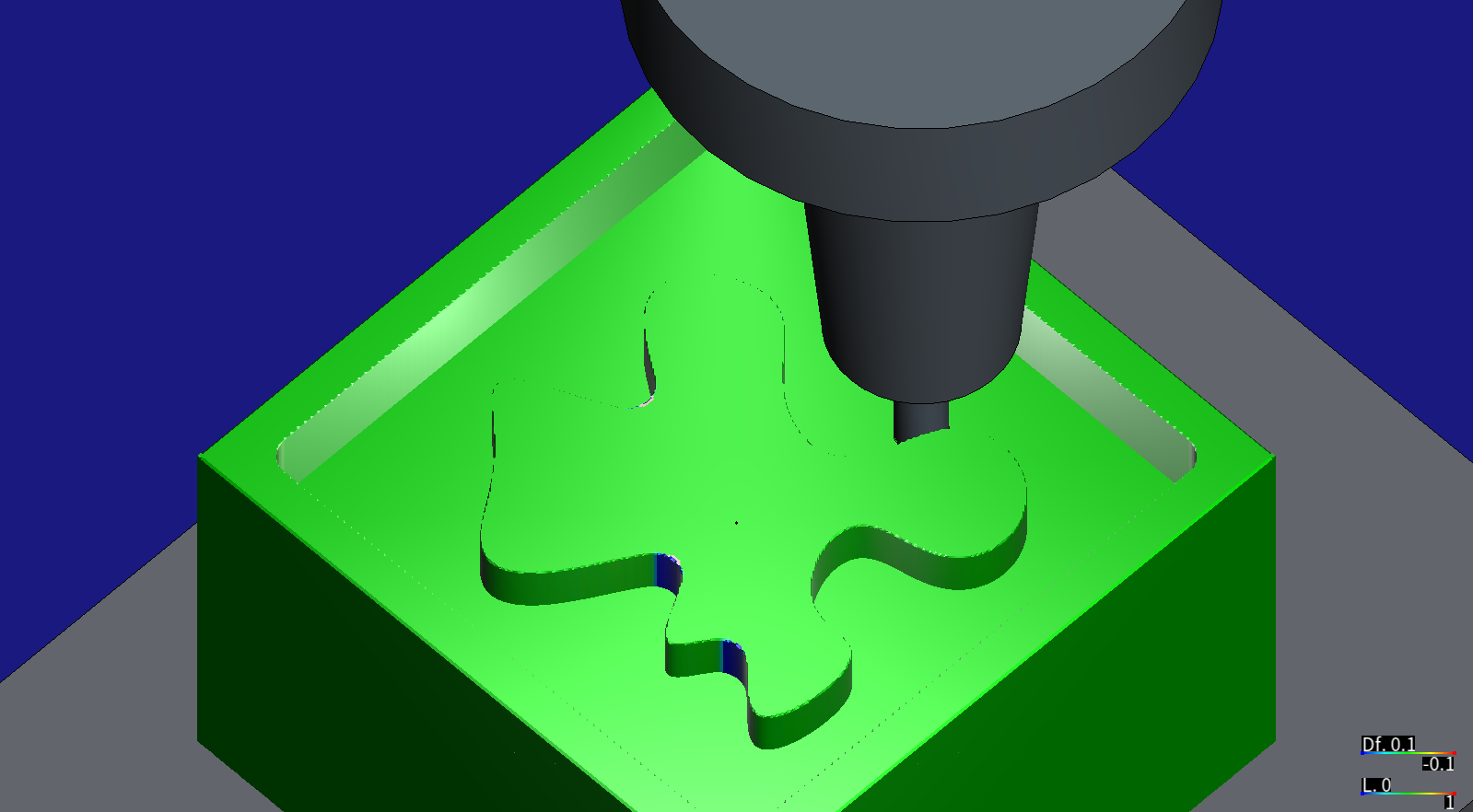
Part 7, HiNC 3.2.41, stopped at the last block of the final contour's Z-11 pass (line 39,999 of 40,014). Green is within ±0.1 mm of the design; blue marks material left beyond it — the three concave bay tips of the island, whose tips are tighter than the Ø6 tool's radius.
The case
The parts are numbers 4 to 10 of the Benchmark Dataset of 10 Multi-Feature Models for Single-Setup 3-Axis Milling (Zenodo, CC BY 4.0; its contact is at RPTU Kaiserslautern-Landau, which is where the name “RPTU” on these pages comes from — the record gives no affiliation for its authors). Parts 1–3 were built the same way by a peer agent and have their own page. For each part the data set publishes three files:
- a STEP model of the finished part;
- an NC program (
.ngc) whose header names a CAM vendor's generic three-axis machine definition, with the tool commentT1 D=6. CR=0.and the deepest depth (ZMIN); - a rendering of the part.
Its description adds that every part comes from an 80 × 80 × 50 mm block with a single end mill of at most 6 mm, without re-clamping, and gives one line of features per part.
What it does not give: where the program's zero is on the block, which controller the program was posted for, the workpiece material, the fixture, and everything about the tool beyond its diameter and corner radius — flute length, number of flutes, angles, holder, stick-out. The machine is described only as a three-axis gantry type, and the NC header says all three axes are on the head.
| Part | Features (read from the data set) | NC lines | Deepest cut (read) |
|---|---|---|---|
| 4 | 4 holes, surrounding step (circular) | 3,676 | Z-8 |
| 5 | 4 holes, surrounding step (semi-circular/semi-rectangular) | 2,509 | Z-7 |
| 6 | 4 holes, surrounding step (rectangular), circular pocket | 6,611 | Z-7 |
| 7 | Square pocket with negative freeform | 40,014 | Z-11 |
| 8 | Multiple inclined surrounding steps (circular and rectangular) | 11,894 | Z-17 |
| 9 | 4 holes, circular pocket, multiple negative freeforms | 71,377 | Z-9 |
| 10 | 4 holes, multiple inclined surrounding steps (circular and rectangular), multiple pockets (circular and rectangular), negative freeform | 14,214 | Z-19 |
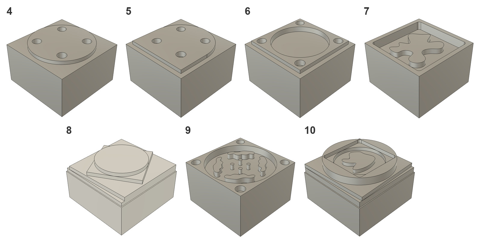
Parts 4–10 as the data set renders them, one .png file per part. Every wall is vertical and every
floor flat (dilemma 4).
What the agent built
One project per part, built entirely through HiNC's web API in the order of the project construction workflow, each value read back after it was written, then saved and reloaded. The last column says where each value came from.
| Item | Value | Origin |
|---|---|---|
| NC program | as published, byte for byte, played unchanged | read |
| Target model | the STEP meshed to STL and moved into program coordinates: (40.5, 40.5, −53) for parts 4, 7, 9; (41, 41, −53) for 5, 6, 10; (28.534, 40.962, −51.056) for 8 | derived from the program's own motion (dilemmas 1, 2) |
| Stock | a box flush with the model's sides and bottom and 1 mm above its top: 80 × 80 × 51 mm (parts 4, 8, 9) or 80 × 80 × 53 mm (5, 6, 7, 10) | derived; the stated 50 mm does not fit (dilemma 3) |
| Program zero | G54 at the stock's top, 0.5 or 1 mm outside the block's front-left corner, as the translation above implies |
derived |
| Controller | HiNC's Fanuc runner | chosen; there is no LinuxCNC runner (dilemma 5) |
| Machine | a generic three-axis machine with no shapes, its table moving in X and Y and its head in Z; travel X −800..0, Y −500..0, Z −500..0. The published machine moves all three axes on the head; for a three-axis program the tool's path relative to the part is the same | chosen |
| Fixture | a 160 × 120 × 20 mm plate under the stock | chosen |
| Material | aluminium alloy 6061-T6 with its cutting parameters, from HiNC's library | chosen; the data set names none |
| Tool | Ø6 flat end mill; 3 flutes, 13 mm flute, 57 mm long, 45° helix, 12° rake, 10° relief, carbide | diameter and corner radius read; the rest chosen |
| Holder | shrink-fit chuck: Ø21 nose tapering to Ø30 over 55 mm, Ø44 body, Ø63.5 flange; 80 mm gauge length | chosen |
| Stick-out | 20 mm (parts 4–7, 9) and 25 mm (8, 10): the larger of the flute length and the deepest cut, plus 5 mm, rounded up to 5 mm | derived by rule (dilemmas 6, 7) |
| Spindle | a generic 24,000 rpm, 7.5 kW spindle | chosen; the programs run at up to 18,000 rpm (dilemma 8) |
| Mission | one program; collision check on; geometry comparison at the end; a coarse run at a 1 mm mesh, then an acceptance run at 0.25 mm | chosen |
| Pass criteria | steps, contact with the stock, every line executed, comparison built, messages accounted for | chosen, before the first run |
Part by part, the design mesh and the tool (mm):
| Part | Design mesh, closed | Stick-out, tool length | Deepest cut | Holder nose above the stock top at the deepest cut |
|---|---|---|---|---|
| 4 | 1,892 triangles | 20, 100 | Z-8 | 12 |
| 5 | 1,532 triangles | 20, 100 | Z-7 | 13 |
| 6 | 1,856 triangles | 20, 100 | Z-7 | 13 |
| 7 | 5,522 triangles | 20, 100 | Z-11 | 9 |
| 8 | 712 triangles | 25, 105 | Z-17 | 8 |
| 9 | 28,544 triangles | 20, 100 | Z-9 | 11 |
| 10 | 4,344 triangles | 25, 105 | Z-19 | 6 |
How the agent managed the work
- Pass criteria written down before the runs. A replay passed only on evidence read back from HiNC: a step count, the “touched the stock” flag at 1, every NC line executed, the geometry comparison built, and a message list with nothing unexplained. A small checker applied these rules to every run, so a finished run that proved nothing could not pass.
- Coarse before fine, small before large. Each part ran first at a 1 mm mesh, then at 0.25 mm. The two largest programs (parts 7 and 9) were first played as excerpts of their first two operations, to prove the set-up before committing the time and memory to the whole program.
- Estimates before runs. Steps were estimated as cutting time × spindle speed, memory at about 5 KB per step (Memory Planning). Runs went one at a time to a 32-thread server.
- One set-up for all ten parts. The build script was taken from the peer agent that did parts 1–3 and only parameterised, so both batches share every choice that is not part-specific; the dialect handling and the tool rule are the peer agent's, confirmed with it before this agent built.
- Adversarial review. The written instructions for each part were checked, claim by claim, by reviewer agents told to refute them — two rounds, seven reviewers each — and this page by one more.
- A blind build. A peer agent got only the shared build guide and part 10's folder — no scripts, no notes — and rebuilt the project.
- Sharing one server. A HiNC service holds one open project for everyone connected to it. The agent and three peer agents worked on showcase cases at once, each on its own service, and said so to the others.
- Where a person stepped in.
- The owner's standing rule for the showcase — every tool in a realistic holder, at the shortest stick-out that reaches — fixed the holder and the stick-out rule.
- The owner named the service the agent should use, and gave it an account when its own rules refused to read one from deployment files (dilemma 19).
- The owner changed what a showcase case is for: from a build instruction for students to this record of the work. The agent then measured part 7's left material from HiNC's own result and took the pictures on this page.
The dilemmas
1. Where is program zero?
- Situation. Nothing in the data set says where the program's
G54is. The STEP models are centred on their own origin: X and Y from −40 to 40, the top face at Z 52 (part 8 is the exception: X from −27.534 to 52.466, the top at Z 50.056). - Risk. A guessed zero moves every cut. The simulation still runs, and the geometry comparison then blames the program for a set-up error.
- How it was noticed. The agent's first guess, a shift of 40 from symmetry, disagreed with the holes' positions in the program.
- Resolution. The zero was read out of the program's motion. For Z, every floor of the model coincides exactly with a depth the program cuts to, and the model's top lands on the facing pass's depth, Z-1. For X and Y, the Ø10 holes are milled by the Ø6 tool on a 2 mm-radius helix, so every helix centre is a hole axis. Matching single arcs was ambiguous — the four holes of a part can be swapped — so the agent matched the mean of the four helix centres against the mean of the four model hole axes. Part 9 was matched through the centre of its Ø75 pocket's finishing circle, and parts 7, 8 and 10 through the finishing passes that run along straight walls, 3 mm (the tool radius) from the model's walls and on the right side of them.
- Evidence that it held. The fits are exact: the helix centres fall on the moved model's hole axes, and the finishing passes run 3.0 mm from the moved walls. The adaptive clearings peak at their layer depth (dilemma 12), and part 7's machined workpiece matches the design everywhere except at the bay tips the tool cannot reach (dilemma 14).
2. The same data set, three different placements
- Situation. Part 4 came out at (40.5, 40.5), like parts 1–3. Part 5 looked like part 4.
- Risk. Copying part 4's numbers to part 5 would place part 5 half a millimetre off. No message would flag it; the geometry comparison would show it only as the program's error.
- How it was noticed. The placement check was run for every part — hole helices for parts 4, 5 and 6, the pocket's finishing circle for part 9, finishing passes along straight walls for 7, 8 and 10: parts 5, 6 and 10 came out at (41, 41), and part 8, whose model origin is not at its centre, at (28.534, 40.962).
- Resolution. Each part carries its own translation.
- Evidence that it held. For all four holes of parts 4, 5 and 6 the helix centres equal the moved model's hole axes exactly, and for 7, 8 and 10 the finishing passes run 3.0 mm from the moved walls.
The placement part by part, with the stock box it gives, the fixture mount at the centre of the
stock's bottom face, and the G54 that HiNC's program-zero call then wrote (mm, program coordinates):
| Part | Matched on | Model moved by | Stock X / Y / Z | Fixture mount | G54 |
|---|---|---|---|---|---|
| 4 | the four Ø10 holes: every helix centre (radius 2) on a model hole axis | (40.5, 40.5, −53) | 0.5..80.5 / 0.5..80.5 / −51..0 | (40.5, 40.5, −51) | (−440.5, −290.5, −529) |
| 5 | the same, all four holes | (41, 41, −53) | 1..81 / 1..81 / −53..0 | (41, 41, −53) | (−441, −291, −527) |
| 6 | the same, all four holes | (41, 41, −53) | 1..81 / 1..81 / −53..0 | (41, 41, −53) | (−441, −291, −527) |
| 7 | the finishing passes along the pocket's straight walls, 3 mm (the tool radius) off them; all six matches agree | (40.5, 40.5, −53) | 0.5..80.5 / 0.5..80.5 / −53..0 | (40.5, 40.5, −53) | (−440.5, −290.5, −527) |
| 8 | the finishing passes along straight walls; the model's centre, (12.466, 0.038) in its own coordinates, lands on (41, 41) | (28.534, 40.962, −51.056) | 1..81 / 1..81 / −51..0 | (41, 41, −51) | (−441, −291, −529) |
| 9 | the centre of the Ø75 pocket's finishing circle | (40.5, 40.5, −53) | 0.5..80.5 / 0.5..80.5 / −51..0 | (40.5, 40.5, −51) | (−440.5, −290.5, −529) |
| 10 | the finishing passes along straight walls; all five matches agree | (41, 41, −53) | 1..81 / 1..81 / −53..0 | (41, 41, −53) | (−441, −291, −527) |
3. The stated stock does not fit the models
- Situation. The data set says 80 × 80 × 50 mm. The programs face 1 mm off the top, and the models below that face are 50 or 52 mm tall.
- Risk. A 50 mm stock would end above the model's bottom, and HiNC's comparison of the machined part with the design would report 1–3 mm of “missing” material that no program could have left.
- How it was noticed. The model heights were measured when the stock box was first computed.
- Resolution. The stock is flush with the model's sides and bottom and 1 mm above its top: 51 or 53 mm tall. The change and its reason are recorded with each case.
- Evidence that it held. The facing pass reads a 1.0 mm cut in every part, and nothing in the comparison flags the part's sides or bottom.
4. “Freeform” — surfaces or outlines?
- Situation. The data set lists “negative freeform” features in parts 7, 9 and 10.
- Risk. Planning for 3D freeform surfaces means a ball end mill, a fine mesh to show curvature, and a different acceptance.
- How it was noticed. Before planning, the agent looked at the renderings and sliced the models.
- Resolution. The walls are vertical, the floors flat, and the outlines are free-form splines; every operation in the programs is a 2D one with a flat end mill. They are 2.5D features. The mesh question became whether the width resolves the smallest feature — part 9's Ø4 pins, sixteen cells across at 0.25 mm.
- Evidence that it held. Part 7's island walls, cut with the flat end mill, match the design at every height except at the bay tips the tool cannot reach and one mark the design's own mesh causes (dilemma 14).
5. A program posted for LinuxCNC (inferred), on a controller HiNC does not have
- Situation. The programs use
G64 P0.01 Q0.01,G91.1and the.ngcextension, which point to a LinuxCNC post-processor. HiNC's controllers are Fanuc, Siemens, Heidenhain, Syntec and Mazak. - Risk. Rewriting the programs would put the agent's edits between the published program and the result.
- How it was noticed. The dialect was checked before any build, together with the peer agent doing parts 1–3.
- Resolution. The programs play unchanged on the Fanuc runner.
G91.1means “arc centres are incremental”, which Fanuc always assumes;G64 P Qis a path-blending tolerance, which the simulation does not model. HiNC reports both asParsing--Unconsumedand plays the same path. - Evidence that it held. In all fourteen replays every NC line executed, and the only warnings
were the three
Parsing--Unconsumed; theG18andG19arcs (in the X-Z and Y-Z planes),G53and the%markers raised nothing.
6. A tool that is “Ø6” and nothing more
- Situation. The only tool data is
T1 D=6. CR=0. - Risk. A tool with no holder, or with more stick-out than it needs, simulates without complaint and misleads anyone who looks at the result.
- How it was noticed. The owner's standing rule for the showcase.
- Resolution. A Ø6 three-flute carbide end mill with a 13 mm flute in a shrink-fit holder, and a stick-out equal to the larger of the flute length and the deepest cut, plus 5 mm, rounded up to 5 mm: 20 mm for parts 4–7 and 9.
- Evidence that it held. HiNC's tool-offset table reads back 80 mm gauge plus stick-out (100 and 105 mm), and both pictures show the holder above the stock.
7. The long tool that was not needed
- Situation. Parts 8 and 10 cut down to Z-17 and Z-19. The agent read that as walls 16 and 18 mm tall — longer than the 13 mm flute — and gave both parts a long tool (24 mm flute) at a 30 mm stick-out. Both replays passed.
- Risk. A tool 5 mm longer than needed is less stiff, and this page would have recommended it.
- How it was noticed. A reviewer agent measured the walls on the model: they are stepped, and the tallest single wall is 8 mm in part 8 (Z-9 to Z-17) and 10 mm in part 10 (Z-9 to Z-19).
- Resolution. Both parts were rebuilt with the standard tool at a 25 mm stick-out and replayed.
- Evidence that it held. The step counts rose by 8 and the simulated time by 0.03 s; depths, forces and messages stayed the same; the final contours' peak depths (8 and 10 mm) stay inside the 13 mm flute; and at the deepest point the holder's nose is 8 mm (part 8) and 6 mm (part 10) above the stock's top.
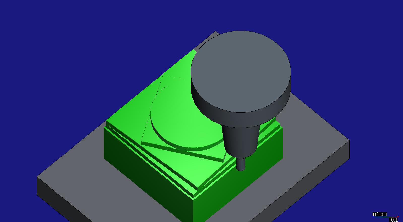
Part 8, HiNC 3.2.41, stopped at the last block of the final contour (Z-17).
8. A spindle that is too slow
- Situation. The programs run at 18,000 rpm (the hole milling of parts 4, 5, 6 and 9 at 16,000); the spindles in HiNC's library stop at 12,000.
- Risk. A spindle below the programmed speed makes the power and torque figures meaningless.
- How it was noticed. While choosing the spindle.
- Resolution. A generic 24,000 rpm spindle was defined for the showcase cases and loaded into each project.
- Evidence that it held. Each project reads the spindle back by name, its 24,000 rpm is above every speed the programs call, and no run reported a missing physics input.
9. How much memory, and for how long?
- Situation. The programs range from 63 kB to 1.8 MB.
- Risk. A simulation that runs out of memory stops near the end, after most of its time.
- How it was noticed. Planned before the first run.
- Resolution. Part 9's path, at its feeds and spindle speeds, estimates to about 408,000 steps and 2 GB of step results. Parts 7 and 9 were checked on excerpts first.
- Evidence that it held. The measured step counts came within −5 % to +7 % of these estimates (part 9: 435,627), and every run finished.
Each part's memory, worked from its measured steps at about 5 KB a step, plus about 1 GB base and an assumed 0.3 GB for the cut surfaces' mesh at 0.25 mm (of the step estimates made beforehand, the record keeps two: about 137,000 for part 4 and 408,000 for part 9):
| Part | Feed-path cutting time | Steps | Step results | Estimated peak |
|---|---|---|---|---|
| 4 | 7.4 min | 131,253 | 0.66 GB | 2.0 GB |
| 5 | 6.8 min | 120,610 | 0.60 GB | 1.9 GB |
| 6 | 9.9 min | 176,026 | 0.88 GB | 2.2 GB |
| 7 | 16.3 min | 316,161 | 1.58 GB | 2.9 GB |
| 8 | 10.1 min | 192,851 | 0.96 GB | 2.3 GB |
| 9 | 22.3 min | 435,627 | 2.18 GB | 3.5 GB |
| 10 | 12.7 min | 239,526 | 1.20 GB | 2.5 GB |
The two excerpts, played at 1 mm: each program up to, not including, its third operation's comment,
then a comment line marking the cut, M5, G53 G0 Z0., M30 and %; both touched the stock and
raised only the three expected warnings:
| Part | Operations played | Lines | Steps | Depth peak | Force peak |
|---|---|---|---|---|---|
| 7 | the facing PLANEN3 and the pocket opening 2D-TASCHE2 |
717 | 98,852 | 2.0 mm | 134 N, in the pocket opening; 54 N in the facing |
| 9 | the facing PLANEN2 and the corner holes' 2D-TASCHE1 |
736 | 107,776 | 4.0 mm, in the hole milling | 54 N, in the facing; 51 N in the hole milling |
10. “Finished” is not “passed”
- Situation. A replay that never mounts a tool produces no steps and still ends “Finished”; the
end-of-play
Play-Touch--Nonewarning needs steps, so often no message says so. - Risk. Accepting a run that cut nothing.
- How it was noticed. Known from the replay acceptance workflow.
- Resolution. Every run was accepted only on the pass criteria above, read back from HiNC.
- Evidence that it held. The checker, once corrected (dilemma 11), passed all fourteen runs.
11. A check that failed for the wrong reason
- Situation. Part 7's first full replay failed the agent's own check: it expected four
Parsing--Unconsumedwarnings, one forG91.1and one perG64line, and HiNC reported three. - Risk. Chasing a build error that does not exist, or loosening the check until it proves nothing.
- How it was noticed. The checker failed on the message count while every other check passed.
- Resolution. The agent read the messages before blaming the build. HiNC reports the first
occurrence of a warning on its own and folds all the later ones into a single entry on the last
line,
[repeated 3x in this run, first at Sn=16], whose count includes the first. Parts 1–6 have one or twoG64lines, where both rules give the same count. The check was corrected: three warnings per replay from twoG64lines up (part 1, with one, reports two). - Evidence that it held. Parts 8, 9 and 10, with 7, 5 and 9
G64lines, each report exactly three, the last one reading[repeated 7x …],[repeated 5x …]and[repeated 9x …].
Part by part (G91.1 is reported at line 8 and the first G64 at line 16; the third entry lands on
the last G64 line, and each play also lists one Sys-Init--FileLines note and nothing else):
| Part | G64 lines |
Third entry |
|---|---|---|
| 4 | 2: 16, 308 | line 308, [repeated 2x in this run, first at Sn=16] |
| 5 | 2: 16, 315 | line 315, [repeated 2x …] |
| 6 | 2: 16, 315 | line 315, [repeated 2x …] |
| 7 | 3: 16, 308, 38,286 | line 38,286, [repeated 3x …] |
| 8 | 7: 16, 315, 3,528, 3,545, 10,711, 10,752, 11,834 | line 11,834, [repeated 7x …] |
| 9 | 5: 16, 309, 734, 906, 68,036 | line 68,036, [repeated 5x …] |
| 10 | 9: 16, 315, 4,147, 4,168, 5,671, 6,796, 12,581, 12,610, 14,154 | line 14,154, [repeated 9x …] |
12. A depth that looked like a datum error
- Situation. Part 5 at 0.25 mm reported a peak cutting depth of 5.89 mm. The program clears in 2 mm layers, and at 1 mm the same part read 2.0 mm.
- Risk. A wrong Z zero looks exactly like this.
- How it was noticed. The peak was compared with the programmed layer depth, as every run's was.
- Resolution. The run was split by operation: each operation's first NC line maps to its first simulation step, and the peaks were read per step range. The 5.89 mm came from the hole milling, whose peak force is 20 N against the clearing's 107 N. Part 4's holes — the same helix, 7 mm deep — read 0.69 mm at the same width, and part 5's read 1.44 mm at 1 mm. So it is not a cut of that depth; the likely reading is the tool's side against the finished hole wall, which the fine mesh registers over the wall's height (inferred, not traced step by step). The depth datum is taken from the adaptive clearing operations.
- Evidence that it held. In every part the adaptive clearings named as the datum peak at 2 mm in both runs, except part 9's, cut in 1.5 mm layers, which reads 1.5 mm at 0.25 mm and 2.0 mm at 1 mm.
13. Finishing passes that take a whole wall
- Situation. The final contour of parts 7–10 reads deeper than any layer: 5, 8, 8 and 10 mm.
- Risk. Mistaking it for a datum error, or not noticing the load it carries.
- How it was noticed. In the per-operation peaks of dilemma 12.
- Resolution. In parts 8 and 10 the final contour is one pass at the bottom: the 78 mm square's wall rises to the step above it on the two sides where that step is flush, and the pass meets all 8 or 10 mm of it at once. In parts 7 and 9 it is two passes (Z-6 then Z-11, Z-6 then Z-9), and the lower pass meets the 5 mm of island wall below the first (part 7) or the whole 8 mm pocket wall (part 9) (inferred from the model and the program).
- Evidence that it held. Each peak equals the wall height left for that pass, and they are the same at 1 mm and 0.25 mm.
14. The comparison has a picture, not numbers
- Situation. The geometry comparison colours the machined part, but the web API gives no way to read its values.
- Risk. Claiming “material is left at the island's bay tips” from geometry alone, without HiNC having shown it.
- How it was noticed. The claim was first written from the model and the tool radius; a reviewer marked it as inferred.
- Resolution. The agent exported HiNC's machined workpiece as STL after a 0.25 mm replay and compared it with the design slice by slice.
- Evidence that it held. At every height of the island (Z-5.5 to Z-10.9) three spots are left, about 2.0, 1.8 and 0.6 mm² in plan and up to 0.7, 0.65 and 0.28 mm thick — the three bay tips, as the geometry predicted — and nothing is over-cut. A fourth, thinner mark (up to 0.2 mm) near X59 Y52 comes from the design STL itself, one of whose facets lies inside the true wall. The comparison on screen marks the three bay tips (the picture above).
15. A screenshot shows the tool where the run ended
- Situation. Selecting a step in the web client highlights it but does not move the tool; the 3D view shows the tool where the replay ended, retracted above the part.
- Risk. A picture without the tool at work, or with the holder out of sight.
- How it was noticed. The first captures showed the tool far above the part.
- Resolution. For each picture the agent played the saved project up to a chosen NC line (the
program's lines up to it plus
M30), captured the view, then reloaded the project so nothing was saved. - Evidence that it held. The two pictures show the tool at the chosen lines; the saved projects are unchanged.
16. The agent's own written claims
- Situation. Each part's instructions were written by the agent from its measurements.
- Risk. A plausible sentence that nobody checked becomes the published fact.
- How it was noticed. By the adversarial review rounds.
- Resolution. Among what they caught: an island given as 55 × 45 mm that measures 49 × 52 mm; the tall wall of parts 8 and 10 placed on the wrong sides; a 3° angle copied from part 8 into part 10, where the edges run at 2.2° and 2.3°; a check that “proved” a helical entry with a number a straight plunge would give too; author affiliations the record does not state; and a licence argument that reached the right answer for the wrong reason. All were corrected.
- Evidence that it held. The first round checked 839 claims and returned 76; after the fixes the second checked 580 and returned 32, smaller ones, which were fixed as well; the blind build then matched every number.
17. What the blind build found
- Situation. A peer agent rebuilt part 10 from the shared guide and the part's folder alone.
- Risk. Instructions that only work for the agent that wrote them.
- How it was noticed. It was the purpose of the blind build.
- Resolution. It reported two traps, both added to the shared guide: a mistyped GET route answers
“200 OK” with the web client's page instead of an error (a mistyped POST answers 405); and a list
entry read back after a play shows that play's run-time values: the Machining Motion Resolution
entry reads the feed per spindle revolution the play left and an infinite rotary step, which the
JSON sends as the string
"Infinity", while the project saves only that entry'sScaleandMinLinearResolution_mm. - Evidence that it held. Its numbers matched the reference on every row: steps, executed lines, per-operation depths, simulated time, program zero and tool length.
18. Sharing a server and a repository with other agents
- Situation. Several peer agents built showcase cases at the same time, on one server and in shared working copies.
- Risk. One agent's project load or reset stops another's run; one agent's commit sweeps up another's files; line endings are rewritten on commit, so the published files no longer match the data set's checksums.
- How it was noticed. A peer agent's run was closed mid-way by an unknown client and the question came to this agent; the shared checkout converts line endings by default.
- Resolution. Each agent took its own service and announced it; this agent's client was fixed to its own. Commits staged exact paths only. The source files were marked “no line-ending conversion”. When a project someone else had left open was in the way, the agent reopened it when done.
- Evidence that it held. None of this agent's runs was interrupted, and the committed source files match the checksums the data set publishes.
19. A login the agent could not read for itself
- Situation. The service required a login.
- Risk. Taking credentials from deployment files would bypass the owner.
- How it was noticed. The agent's own safety rules refused to read them.
- Resolution. The agent asked the owner, who gave it an account.
- Evidence that it held. Every call from then on used that account alone.
Results and benefits
The fourteen replays' numbers were measured on HiNC 3.2.45; part 7's measurement and the two pictures were made on 3.2.41, and the excerpts (dilemma 9) and the long-tool runs (dilemma 7), played while the cases were built, on 3.2.39.
| Part | Steps | Simulated time* | Replay at 1 / 0.25 mm | Depth peak at 1 / 0.25 mm | Depth datum (clearing) |
|---|---|---|---|---|---|
| 4 | 131,253 | 7.6 min | 25 / 70 s | 2.0 / 2.0 mm | 2 mm |
| 5 | 120,610 | 7.0 min | 25 / 60 s | 2.0 / 5.89 mm (hole milling, dilemma 12) | 2 mm |
| 6 | 176,026 | 10.0 min | 35 / 95 s | 2.0 / 5.89 mm (hole milling) | 2 mm |
| 7 | 316,161 | 16.5 min | 65 / 135 s | 5.0 / 5.0 mm (final contour) | 2 mm |
| 8 | 192,851 | 10.4 min | 35 / 90 s | 8.0 / 8.0 mm (final contour) | 2 mm |
| 9 | 435,627 | 22.6 min | 85 / 165 s | 8.0 / 8.0 mm (final contour) | 1.5 mm at 0.25 mm |
| 10 | 239,526 | 13.0 min | 40 / 100 s | 10.0 / 10.0 mm (final contour) | 2 mm |
*The program's path over its feed rates with rapids, as simulated; no acceleration.
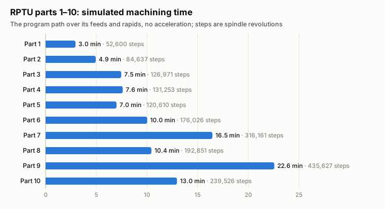
The simulated machining time and the steps of all ten parts; parts 4–10's values are in the table above, parts 1–3's on their own page.
All fourteen replays passed: steps, contact with the stock, every NC line executed, the comparison
built, and only the three Parsing--Unconsumed warnings. HiNC's collision check, which covers the
fixture and also the holder and the shank against the stock, reported no contact in any replay; the
machine has no geometry, so nothing on its side is checked.
Each program operation by operation, as the agent read it: the line of the comment that opens the operation, its steps (the same at both resolutions), and the peaks over them at 1 mm / 0.25 mm, one value where both runs agree:
| Part | Operation (line) | What it cuts | Steps | Depth peak (mm) | Force peak (N) |
|---|---|---|---|---|---|
| 4 | PLANEN2 (11) |
the top face, 1 mm off, at Z-1 | 47,002 | 1.0 | 54 |
| 4 | 2D ADAPTIVE2 (307) |
around the Ø70 disc in 2 mm layers at Z-3 and Z-5, all posted as short G1 segments (3,107 lines); the disc's wall takes about 370 of them a layer |
30,127 | 2.0 (datum) | 107 |
| 4 | 2D-TASCHE1 (3,414) |
the four Ø10 holes, on a helix descending 0.44 mm a turn, at S16000 | 54,124 | 1.44 / 0.69 | 45 / 20 |
| 5 | PLANEN2 (11) |
the top face, 1 mm off, at Z-1 | 48,514 | 1.0 | 54 |
| 5 | 2D ADAPTIVE2 (314) |
around the D-shaped plate in 2 mm layers | 23,483 | 2.0 (datum) | 107 |
| 5 | 2D-TASCHE1 (2,267) |
the four Ø10 holes, helically, at S16000 | 48,613 | 1.44 / 5.89 | 45 / 20 |
| 6 | PLANEN2 (11) |
the top face, 1 mm off, at Z-1 | 48,514 | 1.0 | 54 |
| 6 | 2D ADAPTIVE3 (314) |
around the raised square, down to Z-5 | 16,935 | 2.0 (datum) | 102 |
| 6 | 2D ADAPTIVE4 (978) |
the Ø60 pocket in three 2 mm layers, each entered on a helix | 61,952 | 2.0 (datum) | 111 / 107 |
| 6 | 2D-TASCHE2 (6,369) |
the four Ø10 holes, helically, at S16000 | 48,625 | 1.44 / 5.89 | 45 / 20 |
| 7 | PLANEN3 (11) |
the top face, 1 mm off, at Z-1 | 47,000 | 1.0 | 54 |
| 7 | 2D-TASCHE2 (307) |
the pocket, down to the island's top, at Z-3 and Z-5 | 51,543 | 2.0 (datum) | 134 |
| 7 | 2D ADAPTIVE2 (713) |
around the island in five 2 mm layers, Z-3 to Z-11 | 201,830 | 2.0 (datum) | 114 / 111 |
| 7 | 2D-KONTUR3 (38,285) |
the pocket wall from the faced top to the island's top, one pass at Z-5 | 2,836 | 4.0 | 223 / 218 |
| 7 | 2D-KONTUR2 (38,305) |
the pocket walls and the island, passes at Z-6 and Z-11 | 12,952 | 5.0 | 290 / 281 |
| 8 | PLANEN2 (11) |
the top face, 1 mm off, at Z-1 | 48,512 | 1.0 | 54 |
| 8 | 2D ADAPTIVE6 (314) |
around the Ø54 disc, Z-1 to Z-5 | 46,116 | 2.0 (datum) | 107 |
| 8 | 2D-KONTUR1 (3,527) |
the disc's wall | 2,285 | 4.0 | 167 / 138 |
| 8 | 2D ADAPTIVE7 (3,544) |
around the 54 mm square turned 30°, down to Z-9 | 65,463 | 2.0 (datum) | 111 / 107 |
| 8 | 2D-KONTUR2 (10,710) |
the turned square's wall | 2,931 | 4.0 | 108 / 82 |
| 8 | 2D ADAPTIVE9 (10,751) |
the 1 mm rim, down to Z-17, before the step above it | 12,762 | 2.0 (datum) | 84 / 69 |
| 8 | 2D ADAPTIVE8 (11,312) |
around the inclined step, down to Z-13 | 7,782 | 2.0 (datum) | 107 / 102 |
| 8 | 2D-KONTUR5 (11,833) |
the inclined step's front and left edges | 2,444 | 4.0 | 139 / 102 |
| 8 | 2D-KONTUR4 (11,868) |
the 78 mm square's wall at Z-17, 8 mm high on the back and right, where the inclined step is flush with it | 4,556 | 8.0 | 192 / 156 |
| 9 | PLANEN2 (11) |
the top face, 1 mm off, at Z-1 | 47,002 | 1.0 | 54 |
| 9 | 2D-TASCHE1 (307) |
the four corner holes, helically in 0.58 mm steps, at S16000 | 60,498 | 4.0 / 3.5 | 51 / 23 |
| 9 | 2D-KONTUR3 (732) |
the holes' walls, passes at Z-5 and Z-7, back at S18000 | 5,996 | 4.0 | 210 / 189 |
| 9 | 2D-TASCHE2 (905) |
the pocket, down to the islands' tops | 17,699 | 2.0 | 115 |
| 9 | 2D ADAPTIVE8 (960) |
around the islands and pins, down to Z-9 in 1.5 mm layers | 278,447 | 2.0 / 1.5 (datum) | 114 / 93 |
| 9 | 2D-KONTUR1 (68,035) |
the pocket wall, the islands and the pins, passes at Z-6 and Z-9 | 25,985 | 8.0 | 210 / 165 |
| 10 | PLANEN2 (11) |
the top face, 1 mm off, at Z-1 | 48,511 | 1.0 | 54 |
| 10 | 2D ADAPTIVE3 (314) |
the square pocket, down to Z-5 | 46,486 | 2.0 (datum) | 111 / 107 |
| 10 | 2D-KONTUR1 (4,146) |
the square pocket's 4 mm wall | 2,264 | 4.0 | 223 / 215 |
| 10 | 2D-TASCHE2 (4,167) |
the circular pocket around the island, layers at Z-5.6, -7.2, -8.8 and -9 | 33,448 | 3.8 | 138 / 114 |
| 10 | 2D-KONTUR2 (5,670) |
the island's outline and the Ø52.3 wall, at Z-7 and Z-9 | 7,360 | 6.0 | 120 |
| 10 | 2D ADAPTIVE5 (6,795) |
around the Ø74 disc | 58,678 | 2.0 (datum) | 107 |
| 10 | 2D-KONTUR3 (12,580) |
the disc's 8 mm wall, passes at Z-5 and Z-9 | 5,914 | 4.0 | 167 / 138 |
| 10 | 2D ADAPTIVE7 (12,609) |
the 1 mm rim, down to Z-19, before the step inside it | 19,138 | 2.0 (datum) | 84 / 69 |
| 10 | 2D ADAPTIVE6 (13,450) |
around the inclined step, Z-9 to Z-13 | 10,630 | 2.0 (datum) | 107 / 102 |
| 10 | 2D-KONTUR4 (14,153) |
the inclined step's wall | 2,448 | 4.0 | 139 / 126 |
| 10 | 2D-KONTUR6 (14,188) |
the 78 mm square's wall at Z-19, 10 mm high on the back and left, where the inclined step is flush with it | 4,649 | 10.0 | 192 / 156 |
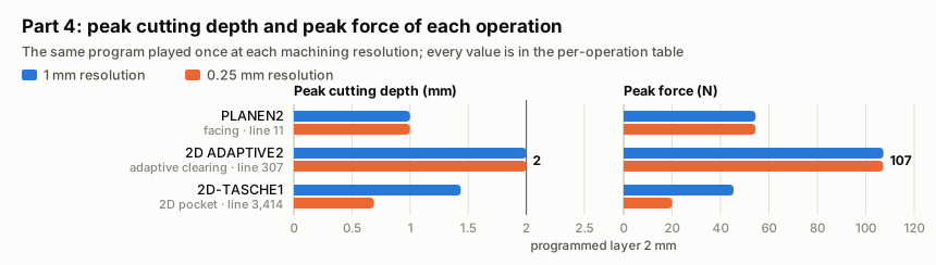
Part 4: each operation's peak cutting depth and peak force at 1 mm and 0.25 mm, against the 2 mm clearing layer; every value is in the table above.
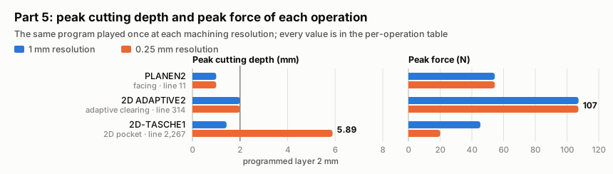
Part 5: each operation's peak cutting depth and peak force at 1 mm and 0.25 mm, against the 2 mm clearing layer; every value is in the table above.
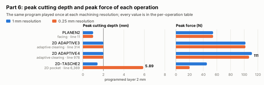
Part 6: each operation's peak cutting depth and peak force at 1 mm and 0.25 mm, against the 2 mm clearing layer; every value is in the table above.
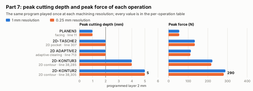
Part 7: each operation's peak cutting depth and peak force at 1 mm and 0.25 mm, against the 2 mm clearing layer; every value is in the table above.
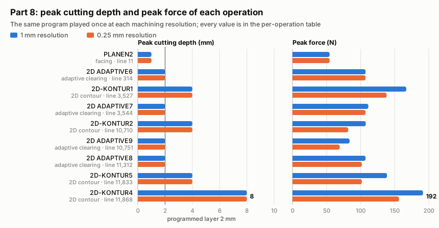
Part 8: each operation's peak cutting depth and peak force at 1 mm and 0.25 mm, against the 2 mm clearing layer; every value is in the table above.
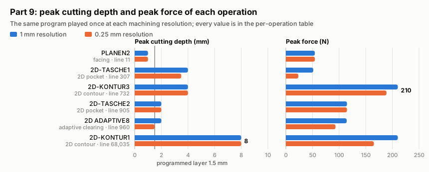
Part 9: each operation's peak cutting depth and peak force at 1 mm and 0.25 mm, against the 1.5 mm clearing layer; every value is in the table above.
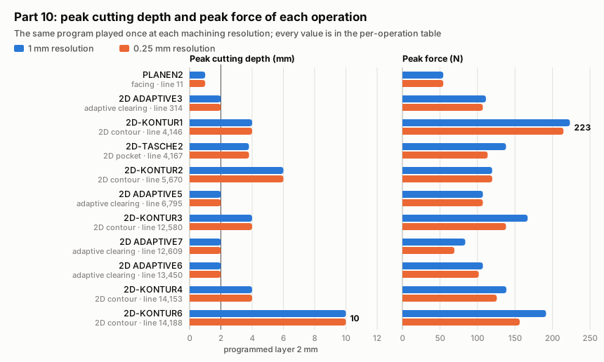
Part 10: each operation's peak cutting depth and peak force at 1 mm and 0.25 mm, against the 2 mm clearing layer; every value is in the table above.
For a machining engineer
- Part 7's program cannot finish its island. Its three bay tips keep about 2.0, 1.8 and 0.6 mm² of material in plan over the island's full 6 mm height, up to 0.7 mm thick: the bays narrow to tips of about 1.4–1.8 mm radius, tighter than the Ø6 tool's 3 mm radius. If the design matters there, a rest-machining pass with a smaller tool is needed.
- Thin walls in part 6. The holes come within 2.5 mm of the raised square's sides and 3.9 mm of the pocket's wall; worth an inspection on a real part.
- Shorter tools are enough. A 25 mm stick-out reaches everything in parts 8 and 10; the obvious long tool at 30 mm is 5 mm longer than needed. At the deepest cut the holder clears the stock by 8 and 6 mm.
- Where the load is. Clearing operations peak at about 84–134 N (1 mm runs; 138 N in part 10's pocketing). The highest peaks are on wall-finishing contours: 290 N on part 7's final contour, 223 N on part 10's first contour (the square pocket's 4 mm wall) and on part 7's pocket wall, 210 N on part 9's hole finishing and final contour, 192 N on the final contour of parts 8 and 10. The 0.25 mm runs read the same or up to about 27 % lower. If deflection or finish matters, those are the passes to split into axial steps.
- Setting up. The program zero sits 0.5 or 1 mm outside the block's corner, depending on the part; touching off on the corner would shift those parts by that much.
- The data set itself. The stated 50 mm block is too low for every model here, and part 10's feature list names four holes the model does not have (its four radius-3 features are the square pocket's corners).
For a teacher or a student
- A simulation that “finished” has proved nothing until it shows steps, contact, executed lines and a clean message list.
- Program zero, stock and tool can be read out of a CAM program's own motion, and should be checked there rather than guessed: in this data set the zero moved between parts.
- One peak value over a whole run can mislead. Split it by operation and compare each with what that operation was programmed to do.
- A data set's description is a claim, not a measurement: here the block height, one feature list and the word “freeform” all needed checking.
- Choose the tool by the tallest single wall and the stick-out by the deepest cut.
For someone weighing whether this approach is worth using
- What it cost. The fourteen replays on this page took about 17 minutes of server time on a 32-thread machine. Building the cases, with the excerpts, the long-tool runs later replaced, the measurement of part 7 and the pictures, took about 40 minutes of server time. The estimated peak memory per run was 1.9–3.5 GB (not measured). The two review rounds took about 40 minutes each and the blind build about 13 minutes, all run by agents.
- What it caught that a single pass would not have. A zero that moves between parts; a stock the data set states wrongly; a tool longer than needed; a depth reading that looked like a datum error; and 76 and then 32 wrong or unclear written claims.
- What it did not replace. A person set the rules the agent worked to, supplied the account, and redirected the work; and nothing here was cut.
Honest limits
- All simulated. The agent cut nothing. Run numbers are HiNC's; the estimates, the holder-nose heights in the part table of What the agent built and part 7's left-material areas are the agent's own geometry, arithmetic or off-line measurement, while HiNC's collision check found no contact between the holder or the shank and the stock in any replay.
- The agent's choices, not the authors'. Material, machine, fixture, spindle, tool geometry beyond the diameter, and the holder are the agent's choices. Forces, power and times depend on them.
- The stock differs from the stated 80 × 80 × 50 mm for the reason in dilemma 3.
- Cycle times have no acceleration model, and the
G64blending the real controller would apply is not simulated. - Inferred explanations are marked as such: the hole-milling depth reading (dilemma 12) and where the final contours meet the whole wall (dilemma 13).
- Part 7's left-material areas come from the agent's off-line slicing of HiNC's exported workpiece; HiNC's own comparison values cannot be read through the API.
- Forces differ between the 1 mm and 0.25 mm runs, by up to about 27 % in clearing and finishing and up to 56 % in the hole milling, whose peaks are low (45 → 20 N).
- Memory per run was estimated, not measured.
What a reader can take to their own case
- Derive program zero from the program: match hole helices, pocket circles or finishing walls against the model, over the whole feature set. A check that the moved model's outline equals the stock's only means something when the stock was given independently.
- Check a stated stock against the model and the facing depth before using it.
- Look at the model before believing a feature list.
- Play the program unchanged when the controller's meaning matches, and list the warnings that remain with the reason each is harmless.
- Choose the tool by the tallest single wall, the stick-out by the deepest cut, and check the holder clearance.
- Estimate steps and memory before the first run; prove the set-up on an excerpt of a large program.
- Write the pass criteria down before running, and read every run against them.
- Read peaks per operation; take the depth datum from a clearing operation.
- When a result looks wrong, read HiNC's messages and the geometry before changing the build.
- Have someone else rebuild the case from your instructions, and have your written claims checked.
Source and licence
M. Schmitz, J. Mertes, F. Schillinger, M. Wagner, Benchmark Dataset of 10 Multi-Feature Models for
Single-Setup 3-Axis Milling, Zenodo, version 1, 2025, https://doi.org/10.5281/zenodo.17035762
(record: https://zenodo.org/records/17035762). Search terms if the link moves:
Benchmark Dataset of 10 Multi-Feature Models for Single-Setup 3-Axis Milling, zenodo 17035762.
Licensed under Creative Commons Attribution 4.0 International. This site offers no download; fetch the files from the record.
Model, NC program and rendering: M. Schmitz, J. Mertes, F. Schillinger, M. Wagner, “Benchmark Dataset of 10 Multi-Feature Models for Single-Setup 3-Axis Milling”, parts 4–10, https://doi.org/10.5281/zenodo.17035762, licensed CC BY 4.0 (https://creativecommons.org/licenses/by/4.0/), provided without warranty.
What was changed: the models were meshed to STL and moved into program coordinates; the NC programs
were played as published in every full replay; the two datum-check excerpts of parts 7 and 9
(dilemma 9) run each program up to, not including, its third operation's comment and end with a
comment line, M5, G53 G0 Z0., M30 and %; and for the two pictures the programs were cut off
at a chosen line with M30 appended (dilemma 15). The simulation set-up — stock, placement, machine,
fixture, tool geometry, holder, material, spindle — is the agent's, as described above; the stock is
51 or 53 mm tall instead of the stated 50 mm (dilemma 3). The pictures on this page are HiNC
simulations of these parts and the charts are drawn from HiNC's replays of them, except the
renderings in The case: the data set's own, cropped, arranged and numbered.
A file fetched from the record can be checked against the one simulated here by its SHA-256, as each part's source notes give it:
| Part | File | SHA-256 |
|---|---|---|
| 4 | 4.ngc |
6240d35afb5e7de046e0249b23072db63f3a20d0aecb756de2419c91f697b1f6 |
| 4 | 4.step |
9779d88de7a615c439a76582341eb8244c2c73acc3e67c64c8332856e19437da |
| 4 | 4.png |
852a37b8bef2c5fa08fa1b6b4d8ed337b8c3b60db879b485462270800130f651 |
| 5 | 5.ngc |
d268fec818e49cbc329969d5ccc29334ca2f0ad8851b1f288caafe6ca60dbf5e |
| 5 | 5.step |
2e77b32274a0b7ab62dcf6ccb8fc47077a8968cce0e3cd466de7abad1cd693f7 |
| 5 | 5.png |
06684bcae0e31ea2bd877b75e73bb8ca4e616883228c9932f417e338e7220706 |
| 6 | 6.ngc |
318245efdccabd466cb53b6a0349242fcda79f82feb7c776187d03338c746d96 |
| 6 | 6.step |
30328dbe66955e34db199c9a36f0674548941c59164c12e48ea3bf4bca5eade7 |
| 6 | 6.png |
392457b9ed3d44dced973098e6ac22e4f84a2d9d2284227fac0af1bce6204534 |
| 7 | 7.ngc |
df9c904dd52e5908006b37744abbff6a9f9cf4094eaf3602dfe3f97e147e6860 |
| 7 | 7.step |
1fdc0a1ccfdf92f6bee6e67c8e29c0308dafee104025923315a58a0998f9cec3 |
| 7 | 7.png |
b93436d7bb4ef3ffaa0692e7126b3fd16bc3b8462c19a48c4e20a43cddfb9842 |
| 8 | 8.ngc |
57b637a6533710dc9e11cc90945edea39bc3d0792d1e7ba7273805dd3af6dfb3 |
| 8 | 8.step |
bb7f3809b3e5610dfde77aaf4cd388426bd06a47267cf021587f6bca23822bb7 |
| 8 | 8.png |
781d89c0dd409571fbe04161102dc5a56e39914692d0e77834d6e5adccc948d9 |
| 9 | 9.ngc |
d944a8d0d40f0c97e5d0f64c097785561503b61f8b1b0eb7b5682f84925445da |
| 9 | 9.step |
3658eb09d100e75cc57e0e18fb7850eb0de456ac141c6b8a17e21141f8edfd32 |
| 9 | 9.png |
c5f99a9dedd360e4a7636a5ee2abb139b3f7c4179b743120eee9809117f56174 |
| 10 | 10.ngc |
4b90bb4a916bcda7f4812298ae1aabe907b2fefbcd18e76e2f901709d4e942b9 |
| 10 | 10.step |
91c23f1fb78ab88b50e9bf46af2f5a08774a56a772d66d8922801a6fbe2001ab |
| 10 | 10.png |
45b0870f7b08e2f9f5f16c84ac7f9d505cfa4129e9e3816a17725ed0ba40323c |