Tool marks on an aluminium block: Ideal Mode against Feedback Mode
The part
A 70 × 50 × 50 mm block of Al6061-T6, a common heat-treated aluminium alloy, and the four NC programs
of HiNC's demonstration project (named DemoStandardPath): a slot 40 mm long and 15 mm wide, a round slot
around a Ø10 boss (10 mm diameter; a round post left standing in it), both 5 mm deep, a side face milled along one edge,
and a sloped band along the opposite edge. In February 2019 the same tool paths cut a block in a cutting
experiment made with a partner, and photos of that block show tool marks.
Tool
One end mill for all four programs: Ø12 mm, three flutes (cutting edges), its bottom corners rounded to a
0.5 mm radius, sticking out 28 mm from a plain cylindrical holder (the part that grips the tool and fits
into the spindle) drawn in the project.
Data
No public source data: the demonstration project and the files of the experiment are not
published. This page shows HiNC's results and photos of the machined block only.
The question
HiNC, from Tech Coordinate, the company behind this website, is machining simulation software: it runs an NC
program on a model of the machine, cuts the part on screen and reports the cutting forces, the machining time,
collisions and how far the result is from the design. Looked at in thousandths of a millimetre, a milled floor
is not flat: the cutting force bends the tool, and the bend leaves marks. The photos of the block show arcs on
the slot's floor and a straight mark on one of its walls. Can HiNC show such marks, and where they fall, before
the part is cut?
HiNC computes a cut in one of two modes
(Ideal Mode and Feedback Mode).
Ideal Mode takes the tool as rigid: it cuts exactly where the program puts it, so the shape cut is the
program's shape. Feedback Mode works out from the cutting force how far the tool bends, its deflection, and
builds that bend into the shape it cuts. An AI agent, an AI program that carries out a whole job by itself,
played the four programs once in each mode, at a machining resolution of 0.03125 mm (HiNC builds the block
from small cubes, and this is the edge of the smallest;
machining resolution)
and one step per spindle revolution (a
step
is HiNC's unit of calculation). It compared each result with the design part, the 3D model of the finished
block, using HiNC's
geometry difference,
which colours every spot by how far it lies from a reference shape, and read it at four
visual radii,
the difference at which the colour turns full blue or full red: 1, 0.1, 0.01 and 0.001 mm. For the walls it
also used the shape Ideal Mode cut as the reference, which leaves only the difference between the two modes.
Positions below are the program's X and Y in mm: the block spans X 2–72 and Y 0–50, the long slot X 15–55
and Y 32.5–47.5.
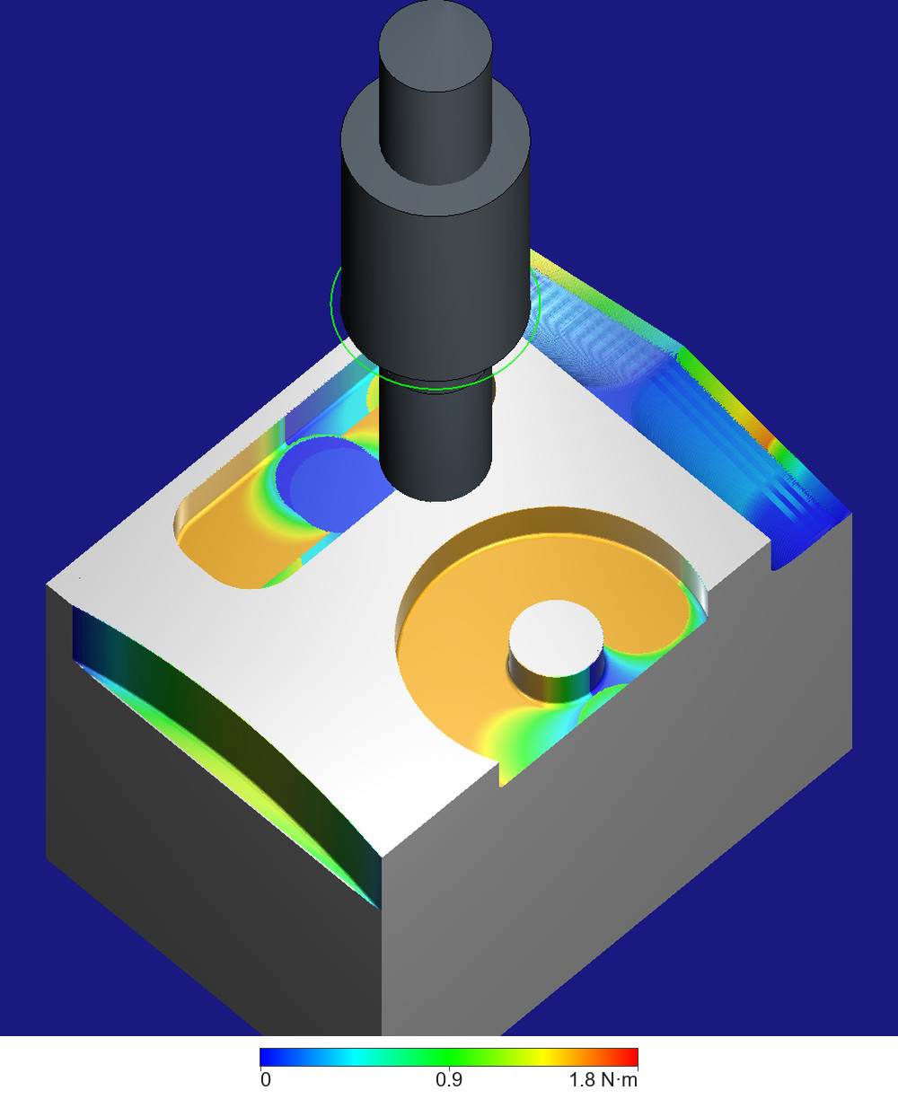
Ideal Mode: the block after the four programs, the tool parked above
it. Each cut face is coloured by the spindle torque (the twisting load the cut puts on
the spindle) of the step that cut it last, from blue at 0 to red at 1.8 N·m, the bar printed below; the
white top face and the grey sides are where these programs do not cut, and the dark blue around the
block is the screen's background. The wide grey cylinder is the holder; the tool sticks
out 28 mm below it, and the thin cylinder on top is the upper end of the same tool. The green
ring marks where a holder with built-in sensors would take its readings; this case has no such
measurement. The machine is hidden.
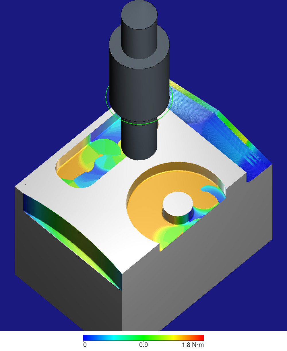
Feedback Mode, same view and colours. The long slot's floor breaks
into wedge-shaped patches, and so does the round slot's near the front: each spot shows the step that
cut it last, and in Feedback Mode the back half of the tool's bottom cuts again the floor its front
half has just cut, so the spot takes the later step's value.
Ideal Mode against Feedback Mode
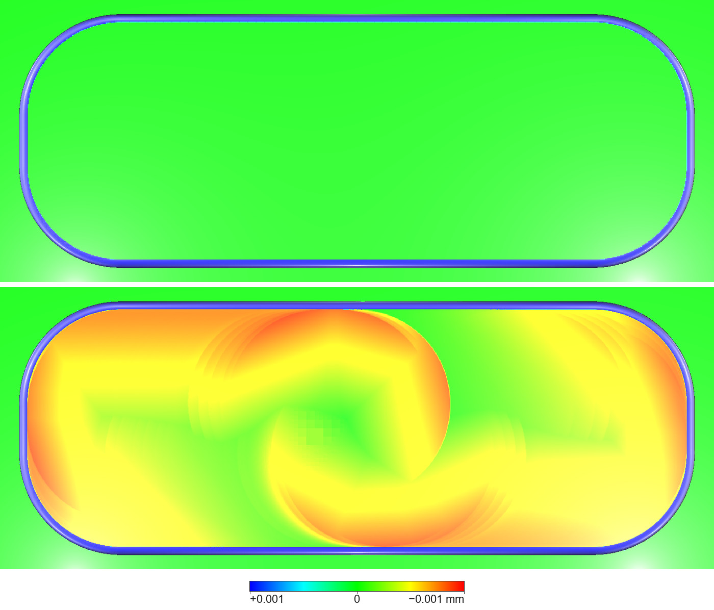
The long slot from above (+X to the right, +Y up), compared with the design
part at a visual radius of 0.001 mm: above Ideal Mode, below Feedback Mode. The colours follow the bar under
the picture: green, no difference; blue, material left compared with the reference, full blue at +0.001 mm
(1 µm); cyan, half of that; yellow to red, cut deeper than the reference, full red at −0.001 mm. In Ideal
Mode the floor is green: it lies exactly at the programmed depth. In Feedback Mode it lies 0.01 to 0.90 µm
deeper: arcs drawn by the edge of the tool's flat bottom, arcs and thin rings around the start hole in the
middle (where the tool spiralled down to depth), and the boundary between the slot's two lanes (the 15 mm slot is cut along two lines 3 mm apart). The
bright green around the slot is the top face; the blue ring along its edge is the 0.5 mm rounded corner the
tool leaves at the foot of the walls, where the design has a sharp corner; the white glow near the lower
corners is a reflection of the lighting. The small chequered patch near the start hole's centre in
Feedback Mode is in the simulation's data; its cause was not looked into.
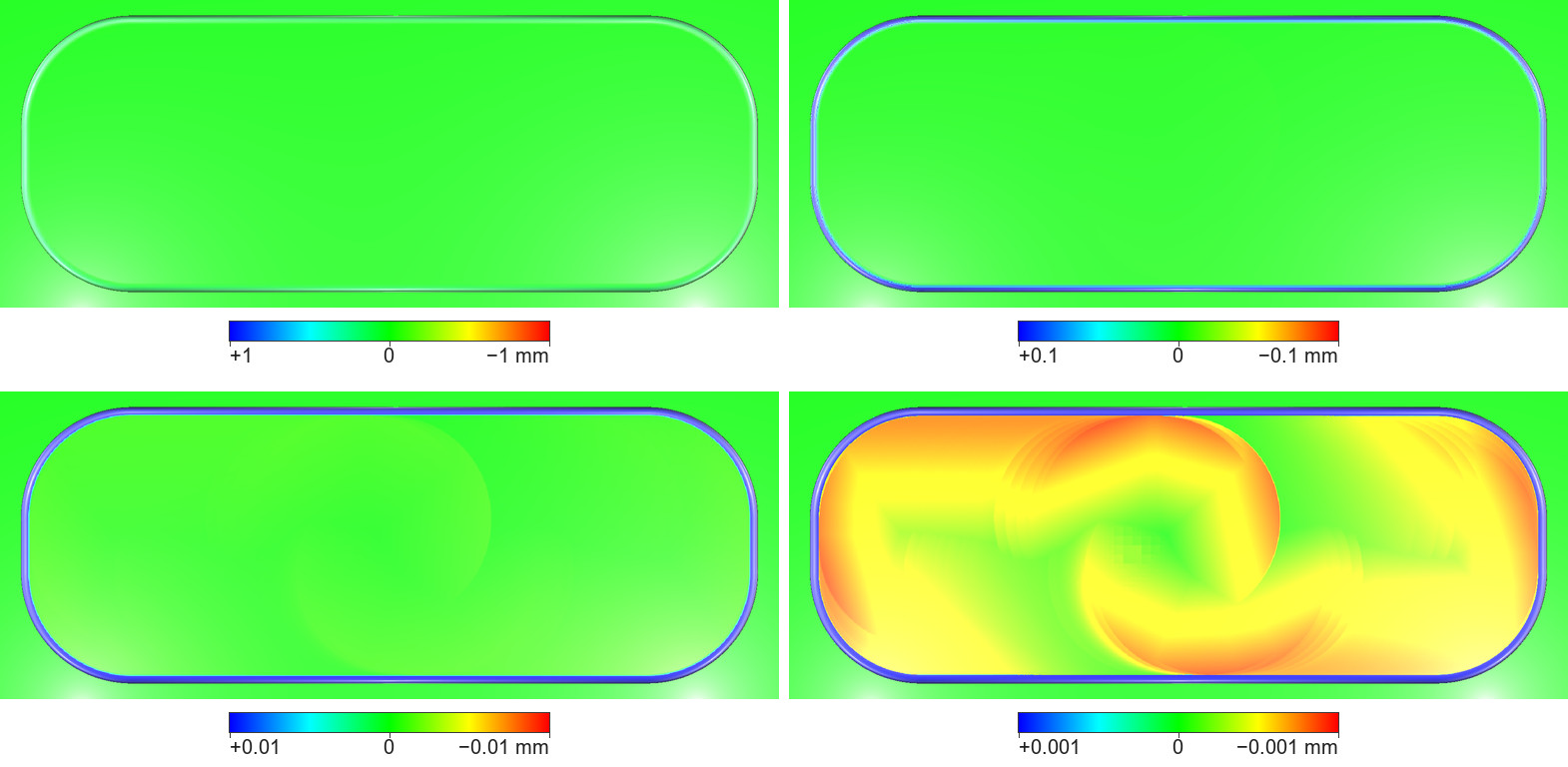
The same Feedback Mode view at four visual radii, each with its own colour
bar: top left 1 mm, top right 0.1 mm, bottom left 0.01 mm, bottom right 0.001 mm. At 1 mm the whole slot is
green: no section of the tool path is missing. From 0.1 mm the rounded foot of the walls turns blue. At
0.01 mm the floor is only faintly yellow-green, since 0.9 µm is 9 % of the scale. At 0.001 mm the marks
show. At 1 and 0.1 mm Ideal Mode looks the same as Feedback Mode.
An animated picture that switches every second, from the same camera,
between Ideal Mode and Feedback Mode: the long slot seen at a slant from the block's front (the −Y
side), looking down at about 56°, +X to the right, compared with the design at 0.001 mm, colours as
above. The white box at the top left names the mode in Chinese and English and gives the visual
radius; the dark blue band along the top is the screen's background. Ideal Mode: the floor and the
top face around the slot are the same green, no difference from the design; the far wall and the end
walls (the curved walls at the two ends of the slot) are dark green, close to no difference; the bright
blue line along the foot of the walls is the 0.5 mm rounded corner. Feedback Mode: the floor is yellow
to orange-red, and the edges of its arcs and patches are the marks; the far wall is blue on the left,
material left compared with the design, turns green at about X 35.5, the offset marked A further
down, and grows bluer again towards +X; the end walls are bluish. The white glare in the middle of the
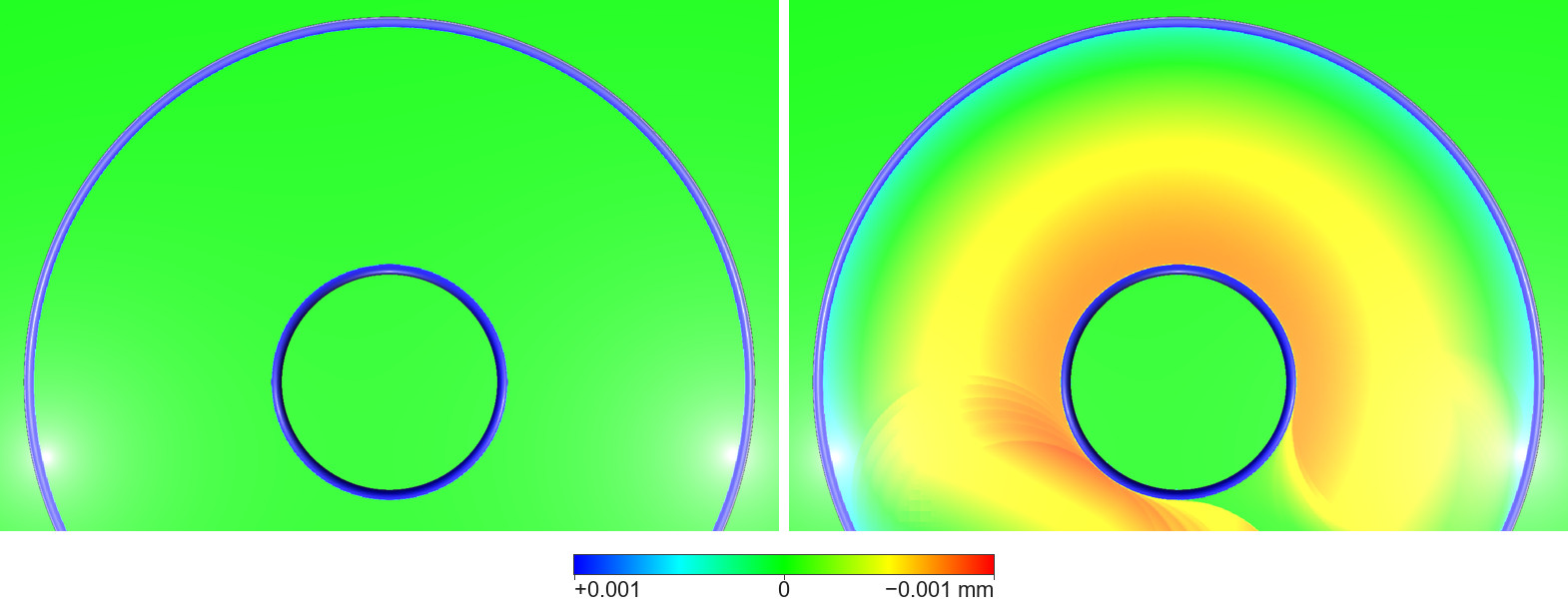
far wall in both is a reflection of the lighting.The round slot from above, compared with the design at 0.001 mm, colours as
above: left Ideal Mode, right Feedback Mode. The circle in the middle is the boss. In Ideal Mode the floor
is green. In Feedback Mode it shades from orange by the boss through yellow and green to cyan near the
outer wall: orange lies below the programmed depth, cyan above it, and the whole round slot's floor
lies between 0.88 µm below and 0.34 µm above. The arcs in front of the boss lie where the circle
starts and ends. The blue rings are the rounded feet of the boss and of the outer wall; the white glow at the lower
sides is a reflection of the lighting.
Against the photos
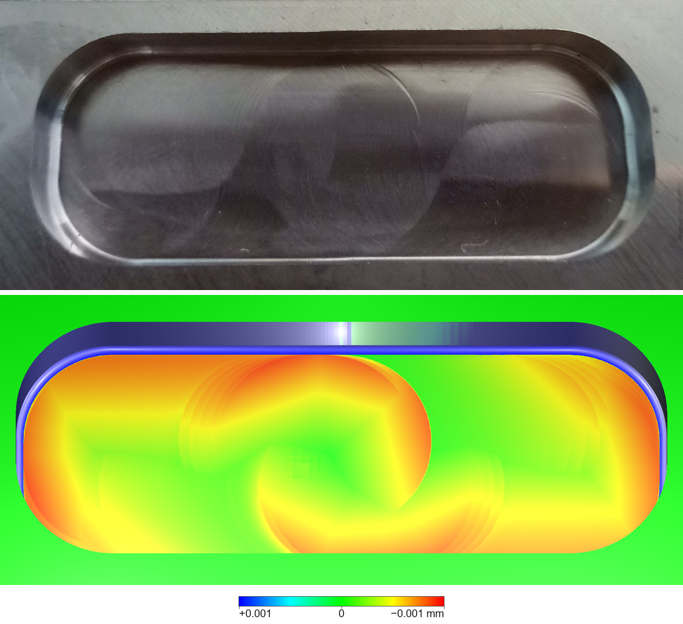
Above: the slot in a photo of the block, taken from its front and
steeply from above, cropped. Two large arcs cross the floor around the start hole in the middle,
smaller arcs lie in the right half, and a boundary runs between the two lanes. Below: Feedback Mode
from about the same side, against the design at 0.001 mm, colours as above. The arcs around the start
hole fall in the same place; where the photo has arcs in the right half, at about X 45 to 52, the
simulation too has arcs drawn by the edge of the tool's flat bottom. The chequered patch at the start
hole's centre is the one above. The far wall is blue on the left, turns green in the middle, at the
offset marked A further down, and grows bluer again to the right; the white flare there is a
reflection of the lighting.
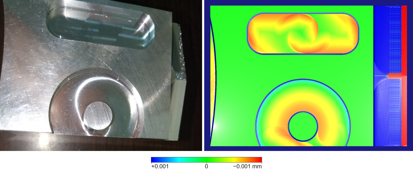
Left: the whole block in a photo from above, turned so that +X points
right: the long slot at the top, the round slot below, the sloped band along the right edge, torn
along the outer edge of its back half. The large arcs on the top face come from flattening the top before these
programs. Right: Feedback Mode from above, against the design at 0.001 mm: both slot floors carry marks;
the sloped band, blue and red on the right, is far from the design, beyond the colour scale; the
curved left edge is the side face seen from above; the dark blue around the block is the screen's
background. The simulation does not tear material.
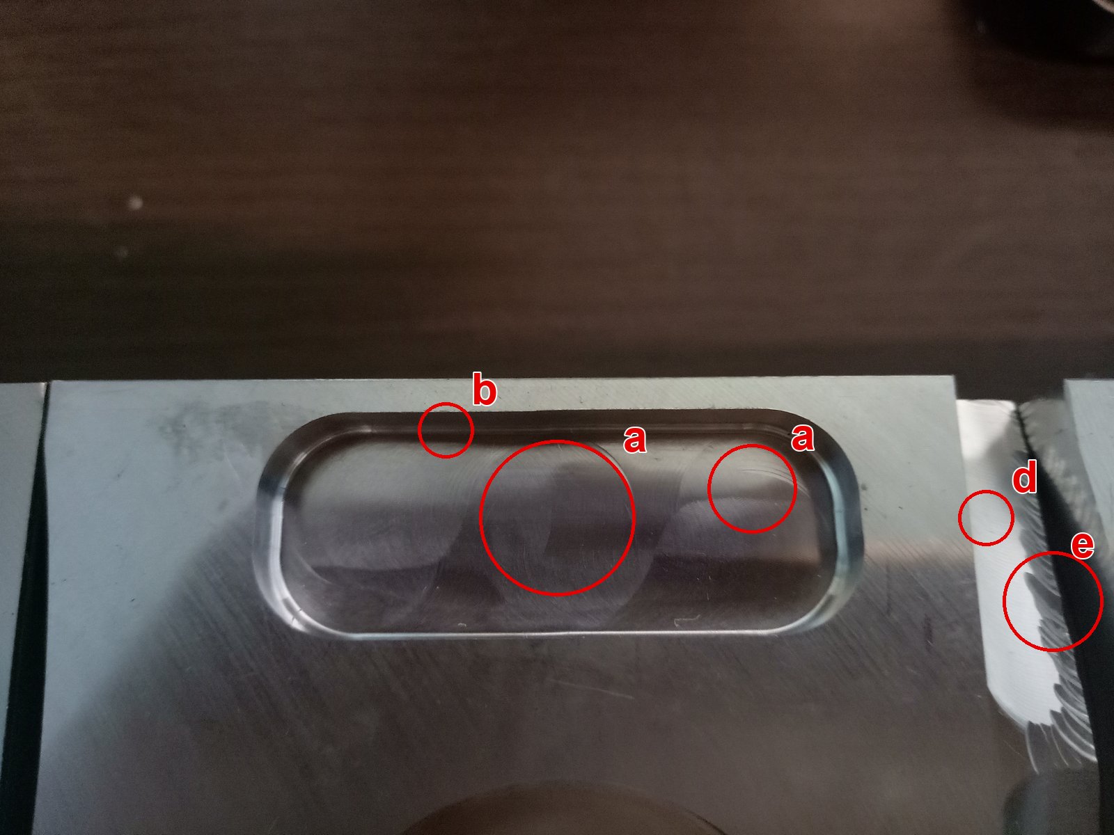
The target block in a photo; every photo on this page shows this
block. The camera is above the block's front, +X to the right and +Y up; the photo is turned
upright and cropped. The red circles and lowercase letters are ours: a, arcs left on the slot's
floor by the edge of the tool's flat bottom, two large crossing arcs in the middle matching the
start hole and smaller arcs to the right; b, a double line at the foot of the far wall; d, the
sloped band; e, the tearing along the band's outer edge. The narrow strip at the left edge is a
neighbouring block, and the small grey patch beyond the tearing at the top right looks like another;
the bottom edge in the middle is the top of the round slot's outer wall, and the dark brown above is
the background.
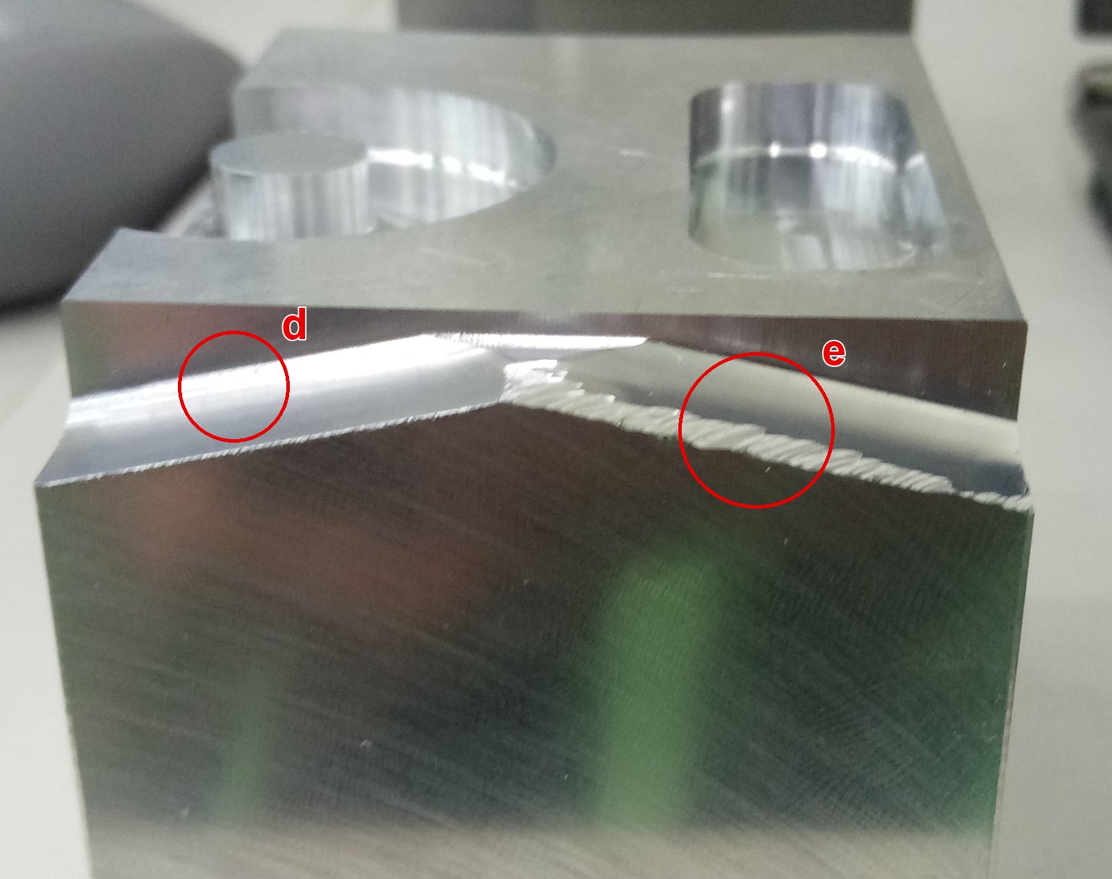
The right face (the +X side) of the same block, photographed on the
day it was cut, cropped. The camera is almost level, a little above; the block's front is on the
left and its back on the right, and the round slot with its boss (left) and the long slot (right)
show on the top face. The top edge is the ridge-shaped slope the sloped-band program cut (low at both
ends, high in the middle): d, its front half, smooth and bright; e, its back half, its top edge torn
into a saw tooth. The red circles and letters are ours; the green vertical streaks on the right
face are reflections of things nearby, and the grey, white and dark things around the block are
the background.
The photos and the simulation are compared for where the marks are, not for
their shape or depth, for the reasons in the problem "What a photograph can be compared on" below; the places
are matched by eye, without correcting the photos' perspective.
The walls: A, B and C
HiNC's product page shows three places on this slot's walls,
A, B and C, in a picture coloured by spindle torque. The tool cuts the slot in three straight passes (runs of
the tool along a line) after spiralling down at its centre: first along
Y 41.5 towards −X to X 21, then along Y 38.5 towards +X to X 49, then along Y 41.5 back to the centre. At
each turn the tool's centre moves 3 mm along X 21 or X 49 to the next pass, and that is when the end walls
are cut: two arcs of 6 mm radius with a short straight piece between them. The +Y long wall is cut by the
first and third passes, the −Y one by the second only. Compared with the shape
Ideal Mode cut, Feedback Mode leaves the long walls further into the slot by a median of 2.4 µm (the middle value: half
the wall stands further in, half less), and marks all three places.
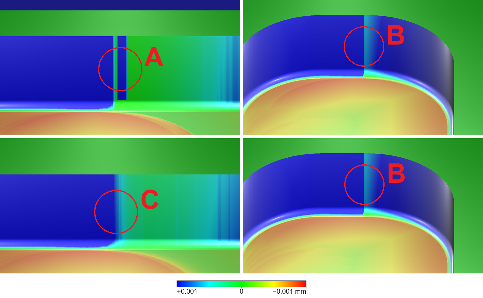
Feedback Mode against the shape Ideal Mode cut, 0.001 mm; green,
the same as Ideal Mode; blue, material left compared with it; yellow to orange, cut deeper than it.
In each view, from the top: the top face (dark green band), the wall, the rounded foot (bright line)
and the floor (yellow to orange: the Feedback Mode floor lies deeper than the Ideal Mode one); the
dark blue strip at the top of A is the screen's background. Top left, A: the +Y wall seen from the
slot's −Y side; blue on the left, 1.3 to 3.9 µm more material than Ideal Mode left, then a thin
green line and a narrow blue strip, then green with cyan vertical streaks to the right. Between
X 35.5 and 36 the material left drops from 3.9 µm to 0.01 µm, an offset near where the first pass,
cutting across the tool's full 12 mm width, meets the third, whose width of cut (how wide a strip
the tool cuts into sideways) is about 1.5 mm. Top right and bottom right, B: the −X and +X end
walls, each with a vertical line in the middle and the two sides left by different amounts; the
vertical line lies where the end of one pass, the turn between passes and the start of the next meet, and
which two of them meet there was not measured piece by piece. Bottom left, C: the −Y wall seen from
the +Y side (+X to the left), shading from blue to cyan-green with no sharp offset; around here the
second pass's width of cut grows from about 1 mm to about 10 mm, and between X 35 and 36.5 the
material left grows from about 1 µm to 3.2 µm, then falls back. The red circles and letters
are ours.
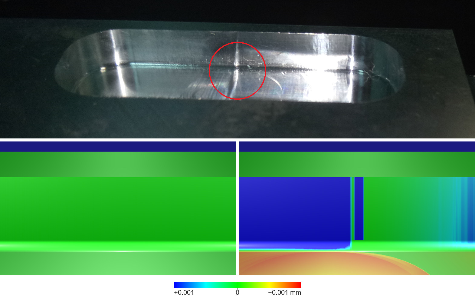
Above: the slot in another photo, from the front at a low angle
(about 30° up), cropped; the red circle marks the straight mark on the far wall, at about X 35.
Below: place A in HiNC, the far wall seen from the −Y side looking down at about 28°, +X to the
right, both against the shape Ideal Mode cut at 0.001 mm: left, Ideal Mode itself, all green, a
check that the reference reads zero; right, Feedback Mode, with the offset, and below it the floor
in yellow to orange, cut deeper than in Ideal Mode. Each, from the top: the screen's background
(dark blue), the top face (dark green band), the wall, the rounded foot (bright green line) and the
floor; colours follow the bar under the picture.
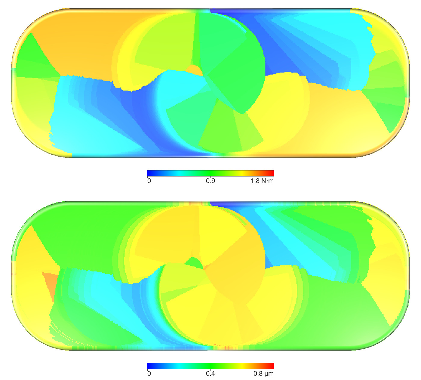
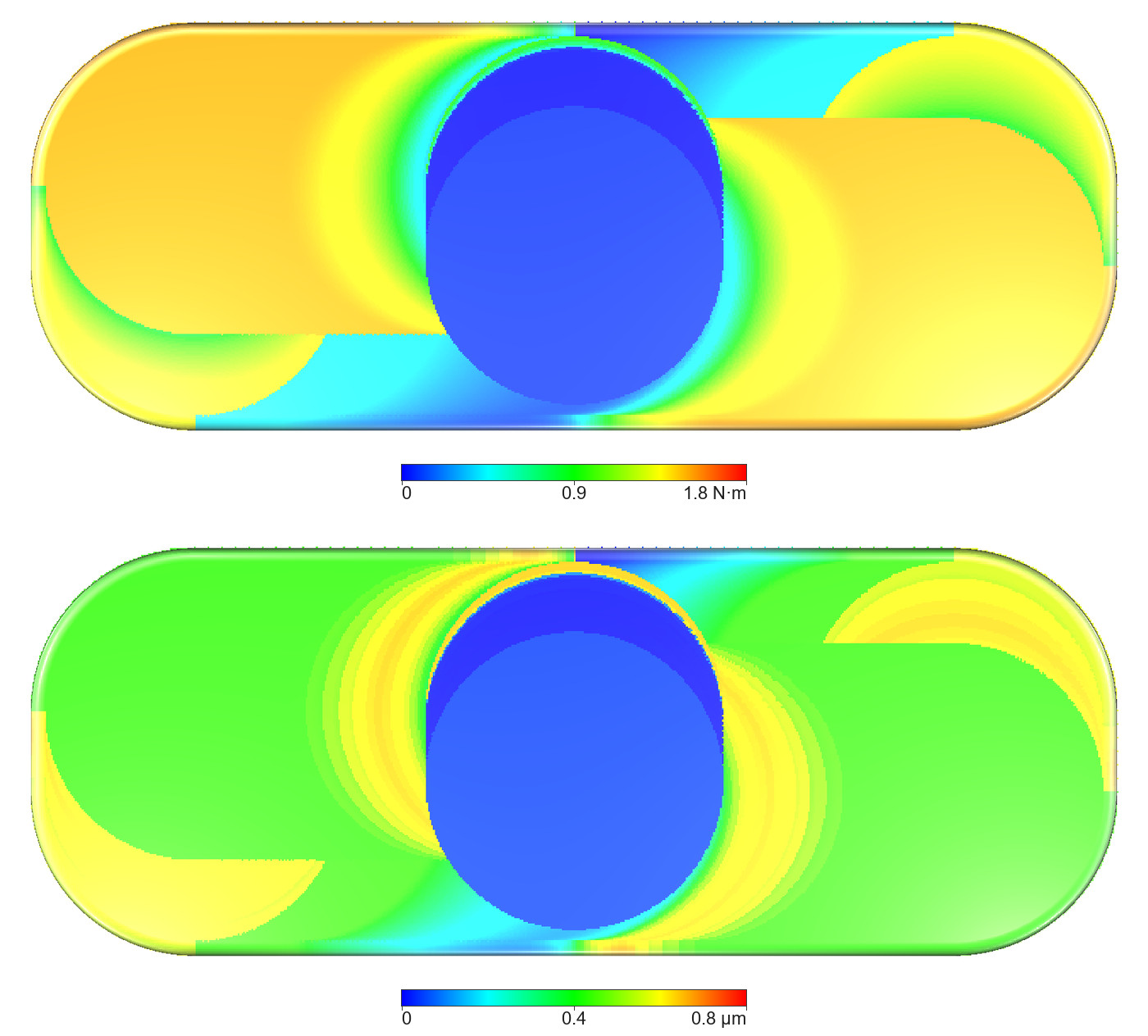
Coloured by each step's values
HiNC can also colour the part's surface by a value it computes for every step, as the product page's picture
does with spindle torque. The two pictures below show the long slot from above (+X to the right, +Y up),
captured before the geometry difference, whose colours would cover the steps' colours.
Feedback Mode. Each spot is coloured by a value of the step that
cut it last, blue for low and red for high. Above, the spindle torque, on a bar from 0 to
1.8 N·m. Below, the
re-cut depth
(a value HiNC computes for every step: how far the tool's deflection moves the outer edge of its
bottom along its axis, which is how deep the back half of the bottom cuts again the floor the front
half has cut), on a bar from 0 to 0.8 µm; it is a simplified reading of the marks the 0.001 mm
geometry difference shows, one value for a whole step, so the walls take it too. The top of each
bar is the largest step value of a trial play on a shortened copy of the slot program (1.74 N·m,
0.74 µm) rounded up. The white
beyond the rim is the top face, which has no step values. The floor breaks into wedges because in
Feedback Mode the back half of the tool's bottom cuts again the floor already cut, and the spot
takes the later step's value.
The same layout and bars in Ideal Mode. The colours run in smooth
bands, drawn the way the product page's picture is. The blue disc in the middle is the start hole's
floor: spiralling down, each step cuts very little, and the torque is close to 0 (about 0.06 N·m,
the median of those few thousand steps). The arcs on either side of the start hole are where the
three passes start and end. The re-cut depth below is not zero: Ideal Mode computes every step's
deflection and re-cut depth too (a median of about 0.4 µm on the three straight passes) but does
not build the deflection into the shape it cuts, so its floor still lies at the programmed depth
at every point. The white beyond the rim is again the top face.
Four of the problems it met
Which block is in the photos?
The experiment's photos show at least four blocks with both slots, in
aluminium and in stainless steel, cut with the original programs or with an optimised set. Only the
original programs cut the sloped band, and of the two blocks that have one, only the aluminium block
is torn along it. The experiment's notes say the band was first cut with too large a width of cut and damaged the part.
That tearing, in the photo of the right face above, identifies the block; HiNC does not simulate tearing, and the page does not claim it
predicted it.
What a photograph can be compared on
The photos and the simulation are compared only for where the marks fall:
the arcs around the start hole, and the straight mark on the far wall near X 35, near where two
passes meet. Shape and depth are not compared, for three reasons: a photo cannot measure depths of a
few µm; the places in the photos are worked out by eye from the slot's width, without correcting
the perspective; and how far the tool bends depends on its stick-out (how far it reaches out of its
holder) and its flute length (the length of the part that carries the cutting edges). The project
sets a 28 mm stick-out and a 20 mm flute length; there is no record of the stick-out on the day of
the experiment to check them against.
The walls need another reference
Against the design, the 0.5 mm rounded foot of every wall reads as material
left far beyond the 0.001 mm scale, since the design's corner is sharp, and the side face and the
sloped band differ from the design by more than 0.1 mm. To see the walls' marks clearly, the agent
exported the shape Ideal Mode cut and used it as the reference for the Feedback Mode result: only
what the bending adds is left. Ideal Mode against itself reads all green.
One step per revolution is enough here
HiNC can also take a step for each flute's cut, three per revolution with
this tool. On a shortened copy of the slot program, Feedback Mode took three to four times as long
that way, and the floor differed from the one-step-per-revolution play by −0.06 to +0.08 µm at 98 % of
the points (at most 0.55 µm); at 0.001 mm the pictures matched except for slight differences in the arcs at the two ends.
The full plays used one step per revolution.
The full record, the detailed version of this case on HiNC's documentation site, has more views
and the numbers behind them.
The result
Both plays ran the four programs to the end, with no collision and no rapid move (the machine's fastest
move, meant for the air) through material: 16,391 steps each, counting two short programs that only move the
tool through the air to frame the views and park it. In Ideal Mode the floors of both slots lie
exactly at the programmed depth at every point measured. In Feedback Mode the long slot's floor lies 0.01 to
0.90 µm below it (median 0.47 µm), and the round slot's from 0.88 µm below to 0.34 µm above (median 0.38 µm
below); the marks show at a visual radius of 0.001 mm, only faintly at 0.01 mm, and not at 0.1 or 1 mm, where
both modes look the same. On the walls Feedback Mode marks A, B and C. The arcs around the start hole and
the straight mark on the far wall sit where the photos show them. The agent measured these heights on the
shapes HiNC exported as STL files (the surface as small triangles), not off the colours, which agree with
them. A play took 21.6 minutes in Ideal Mode and 27.5 minutes in Feedback Mode, about 1.27 times as long, on
a 32-thread server (it runs 32 calculations at once) shared with other work, which can shift such times by
tens of percent; the peak memory was about 7.8 to 7.9 GB in both modes.
Key number
What it is
16,391
steps in each play, one per spindle revolution, at a machining resolution of 0.03125 mm: the four programs and two short ones that only move the tool through the air to frame the views and park it
0 µm
Ideal Mode: how far the floors of both slots lie below the programmed depth, at every point measured
0.01–0.90 µm
Feedback Mode: how far the long slot's floor lies below the programmed depth (median 0.47 µm)
0.88 µm below to 0.34 µm above
Feedback Mode: the round slot's floor against the programmed depth (median 0.38 µm below), higher near the outer wall
0.001 mm
the visual radius at which the marks show; at 0.01 mm they are faint, at 0.1 and 1 mm the two modes look the same
3.9 µm
the offset at A in the +Y wall, between X 35.5 and 36 mm, Feedback Mode against the shape Ideal Mode cut
2.4 µm
median of how much further into the slot Feedback Mode leaves the long slot's two long walls than Ideal Mode
5.5 mm
radius of the arcs the tool's edge leaves on the floor: the tool's 6 mm radius less its 0.5 mm corner
21.6 · 27.5 min
one play in Ideal Mode and in Feedback Mode on a shared 32-thread server, about 1.27 times as long; peak memory about 7.8–7.9 GB
What it brought
For a machining engineer: Ideal Mode checks the program's paths; Feedback Mode adds the
tool's bending and shows, before the part is cut, where it leaves marks: here arcs and the lane boundary,
under 1 µm deep, on the floor, an offset of about 4 µm in a wall near where two passes meet, and a gradual
change in a wall where a pass changes how wide it cuts.
For a teacher or a student: the same view at four visual radii, and the same view in the
two modes, separate what the program's path does from what the tool's bending adds; the marks in the photos
of a real block sit where Feedback Mode puts them.
For someone deciding whether to use an AI agent with HiNC: the agent ran the plays one at
a time on a shared server, checked after each play that the mode was set as intended, captured every view
from set camera positions, measured the exported shapes and matched every photo to the program feature it shows.
People chose the case and the photo of the target block.