Tool Marks on an Aluminium Demonstration Block: Ideal Mode against Feedback Mode at 0.001 mm, beside Photographs of the Block as Cut
HiNC's demonstration project cuts a ring-shaped pocket round a boss, a slot, a side face and a sloped band into an aluminium block with one Ø12 mm end mill. An AI agent played its four NC programs through HiNC's web API in Ideal Mode and in Feedback Mode, and compared each finished block with the design and with each other through HiNC's geometry difference (the Diff: the machined surface coloured by how far it lies from a reference). In Ideal Mode the tool is taken as one that does not bend, and the block comes out in the program's shape: at a visual radius of 0.001 mm (the deviation at which the Diff's colours saturate) the slot's floor reads one even green. In Feedback Mode HiNC shifts each step's cut by the tool's deflection under the cutting force, and the same view shows the tool marks, the lines and steps a cutter leaves on a machined surface: arcs of the cutter's edge round the slot's start hole and where each pass starts, the boundary between the slot's two lanes (the strips its passes cut side by side), and on the slot's far wall a step of 3.9 µm near where two passes meet. Photographs of the block, cut with the same programs in 2019, show marks in the same places; only the places are compared.
This case has no public source data: it starts from HiNC's own demonstration project and from photographs of a block cut in a cutting experiment run with a partner. The page shows the simulation results, the pictures and the explanation; no model, NC program or project is offered. Every number below was measured on HiNC 3.2.57 but one, from an earlier study of the same block and marked as such. Each dilemma gives its situation, the risk had it been missed, how it came to light, the resolution and the evidence that it held. The project the agent played was its working material and is not distributed.
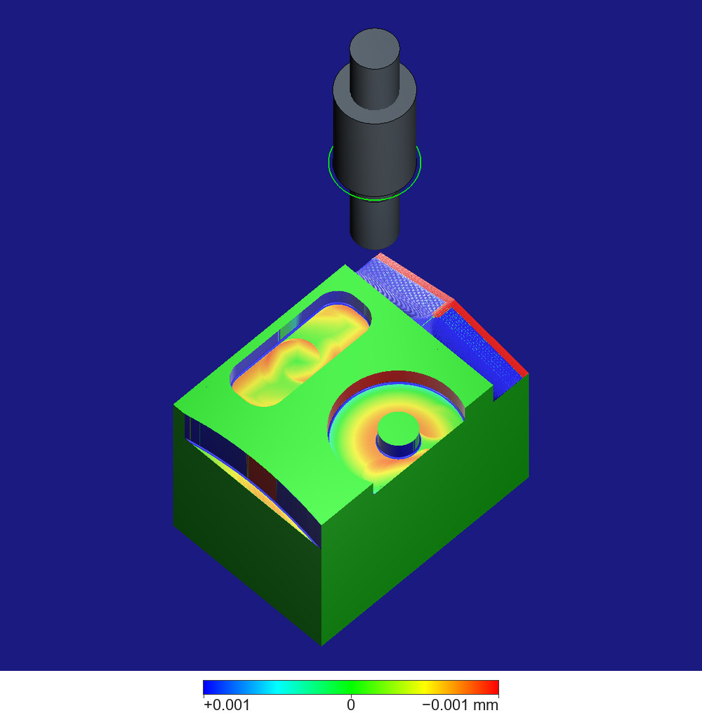
The block after Feedback Mode, compared with the design at a visual radius of 0.001 mm, seen from above its front-left corner. The colour bar under the picture runs from +0.001 mm (blue: material left where the design has none) through 0 (green) to −0.001 mm (red: cut deeper than the design); beyond either end the colour stays at the end's, and faces turned from the light show the same colours darker. The dark blue all round is the background of HiNC's view, not the block. Green: the top face and the uncut parts of the front and left faces, a difference of 0, as these programs do not cut them. Green to yellow and orange-red: the two floors, from almost on the design's floor to 0.9 µm below it; by the pocket's outer wall the floor turns green to cyan, up to 0.34 µm above it. Red-brown: the pocket's outer wall, cut further out than the design. Dark blue: the slot's walls and the boss's wall, which Feedback Mode leaves mostly about 2.5 µm proud; on the boss's front, right of its middle, the wall is dark green, almost at its programmed place, and the thin dark-blue vertical line there is the raised strip described under Honest limits, which this page does not count as a tool mark. Saturated blue and red: the sloped band at the upper right and the side-milled band along the top of the left face, where the design model is not the shape these programs cut, by 0.1 mm and more; the narrow yellow strip at the side face's foot is the step that program leaves, lowered like the floors. The thin blue line round each rim is the 0.5 mm wall-foot fillet the cutter's corner leaves and the design's sharp corner does not have. Above the far corner the tool T1, Ø12 mm, stands 28 mm out of the cylindrical holder the project defines (Ø20 mm, the wide grey cylinder); the narrow cylinder on top is the upper end of the cutter's shank, which the project models longer than the holder. The green ring at the holder's nose is where HiNC marks the observation point of a smart holder, a holder with a built-in sensor (Cutter), drawn because the physics options were shown; this case uses no smart holder. The machine is hidden. Captured on HiNC 3.2.57.
The case
HiNC's demonstration project holds an Al6061-T6 block 70 × 50 × 50 mm: X 2 to 72, Y 0 to 50 and Z −50 to 0 in the programs' coordinates, Z 0 being the top face, Y 0 the front face. It carries a design model of the finished block, four Fanuc programs that all use one tool, T1, and a machine. The programs, read from their own lines:
| Program | What it cuts |
|---|---|
Pocket, circle.ptp |
a ring-shaped pocket round a Ø10 mm boss centred at (35, 7): radius 5 to 17 mm, floor at Z −5, the tool centre on a circle of radius 11 mm; the outer wall breaks through the front face over X ≈ 19.5–50.5 |
Slot, drill_slot.ptp |
a slot X 15–55, Y 32.5–47.5 with its floor at Z −5. A helical entry at (35, 40), about 130 turns with the tool centre on a 1.1 mm radius, opens a start hole about 14 mm across (X ≈ 28–42); then three straight passes in two lanes: pass 1 along Y 41.5 towards −X to X 21, pass 2 along Y 38.5 towards +X to X 49, pass 3 along Y 41.5 back to X 35. Between passes 1 and 2 the tool centre moves a short way along X 21, between passes 2 and 3 along X 49; the slot's end walls are what the tool cuts as it turns there, two arcs of the tool's 6 mm radius with a short straight between them. The far long wall (Y 47.5) is cut by passes 1 and 3, which meet at X ≈ 35; the near long wall (Y 32.5) by pass 2 |
Side, side.ptp |
the top 10 mm of the left face (X 2) on a slightly curved path, the cut from 0 at either end to about 2.3 mm wide near Y 24, leaving a narrow step at Z −10 |
Slope, slide.ptp |
a band X 60–72 along the right edge, roof-shaped along Y: Z −5.8 to −5.9 at the front face, rising at about 12.5° to a flat top at Z −1.6 between Y 19.6 and 30.4, and down to Z −5.8 at the back; the tool centre steps 0.68 mm towards −X per pass |
The spindle turns at 5,000 rpm in every program; the feed is 500 mm/min in the pocket and the slot and 1,400 mm/min on the side and the slope, which with three flutes is 0.033 and 0.093 mm per tooth (derived). T1 is a Ø12 mm three-flute carbide end mill with a 0.5 mm corner radius, a 20 mm flute length and a 50° helix, 28 mm out of its holder.
In February 2019 the same four programs cut an aluminium block in a cutting experiment run with a partner; the project's copies differ from the experiment's in two lines only, adding a tool change on a line the experiment's leave empty and writing the spindle start's two words in the other order. The block was photographed on 14 and 18 February. HiNC's product owner asked for this case: Ideal Mode against Feedback Mode, the Feedback Mode result compared in a Diff fine enough to show tool marks, set beside the photograph he named of the block whose right edge is torn.
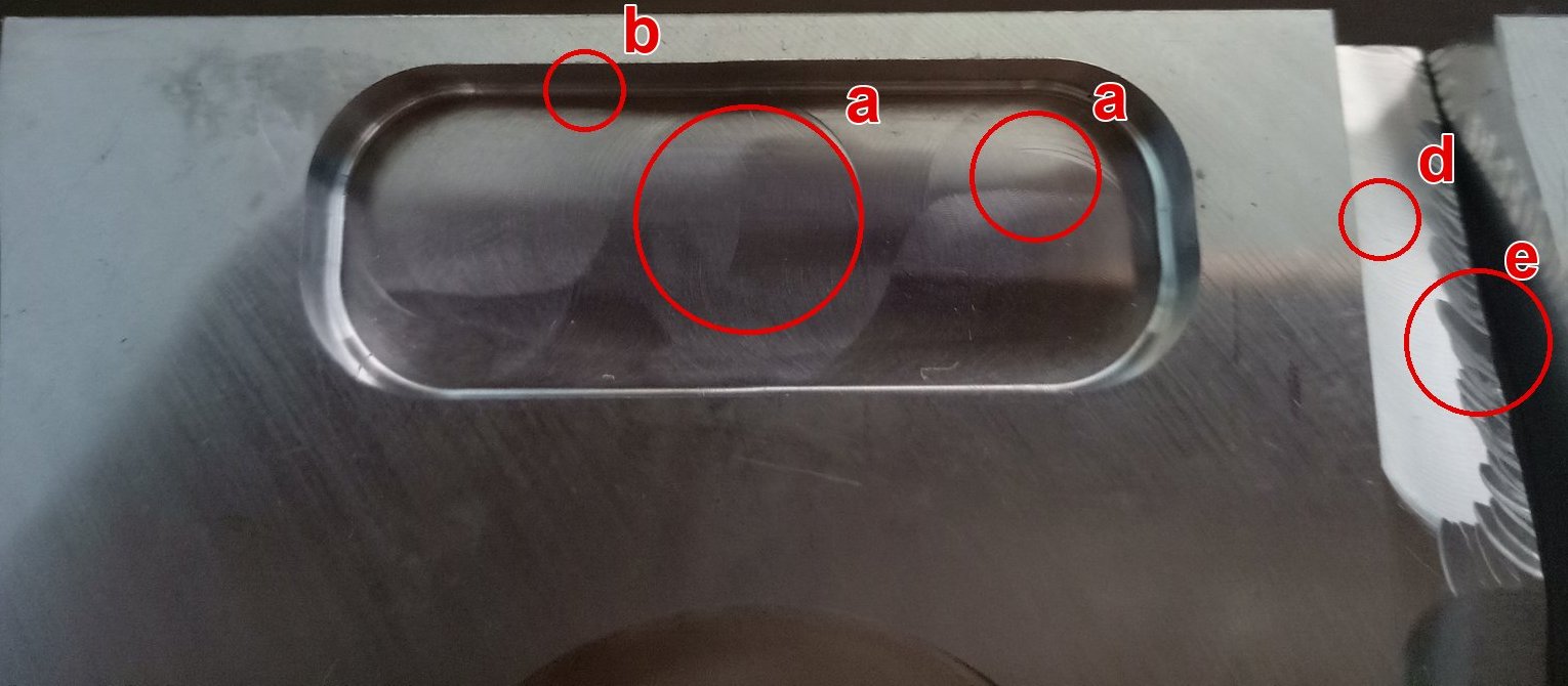
The block the owner named, photographed on 18 February 2019 from above its front face, +X to the right, cropped to the block. The red circles and letters are the agent's marks: a, curved marks on the slot's floor, the larger in the middle where the start hole was cut and smaller ones towards the +X end; b, a double line along the foot of the far wall; d, the sloped band the slope program cut; e, its outer side torn away. The dark curve at the bottom edge is the top of the ring-shaped pocket.
What the reader does not get: the project, its model and its programs. What the agent could not find: the original images of the three photographs, A, B and C, that HiNC's product page shows beside a slot coloured by spindle torque; they are not among the experiment's photographs and videos it searched (dilemma 2).
What the agent built
Everything went through HiNC's web API, following Driving the Web Service over HTTP and Replay Acceptance over the HTTP API. Each value is marked read (from the project or its programs), chosen (by the agent) or measured (in a play).
| Item | Value | Basis |
|---|---|---|
| Project | the demonstration project, copied and opened on a HiNC service of the agent's own; the project itself was never saved | Chosen |
| Physics | a Physics command added at the top of the mission: Enable Physics on, Feedback Mode off for the Ideal Mode play and on for the Feedback Mode play. Feedback Mode is two project switches, the chip-stock truncation and the deflection transformation; after every play the agent read both back: off and off, on and on | Chosen; switches measured |
| Machining resolution | 0.03125 mm, the edge of the cubes the simulated block is built from (Mesh Resolution) | Chosen: in an earlier study of the same block, the pocket's steady cross-sections at the project's own 0.015625 mm and at 0.03125 mm differed in floor height by at most 0.0024 µm; the finer took 4.6 times the time and 3.1 times the memory |
| Motion resolution | one step per spindle revolution, Feed Per Cycle; a step is HiNC's unit of computation | Chosen on the trial plays (dilemma 6) |
| Programs | the four, in order: pocket, slot, side, slope; then two of the agent's that cut nothing: one that feeds along a line 2 mm above each area, to frame the camera on, and one that parks the tool above the block, so that the holder stands in the pictures | Read; helpers chosen |
| Tool and holder | T1 and the cylindrical holder, Ø20 × 30 mm, as the project defines them | Read |
| Material | Al6061-T6, with the project's cutting-parameter file for it | Read |
| Machine, controller | the project's machine and its Fanuc controller model; the machine is hidden in every picture | Read |
| Collision check | on, as in the project | Read |
| References for the Diff | the project's design model, detection radius 1 mm (the distance up to which the Diff computes a deviation); and the Ideal Mode block exported as STL, detection radius 0.05 mm | Read; second reference and radii chosen (dilemmas 3 and 5) |
| Visual radii | 1, 0.1, 0.01 and 0.001 mm on one comparison, as Reading the Difference at Several Visual Radii describes | Chosen |
| Block coloured by step | before the Diff, which replaces those colours: the spindle torque (HiNC's Avg Abs Torque, the step's average absolute torque, N·m) on a scale of 0–1.8 N·m, and the re-cut depth on 0–0.8 µm; each upper end rounded up from the largest value of the trial plays, 1.74 N·m and 0.74 µm | Chosen |
| Graphic Cache | the memory budget of the block's rendering cache (Graphic Cache): 1,200 MB in the plays and on the services that drew the Diff; 600 MB for the step colours drawn on the playing service | Chosen (dilemma 9) |
How the agent managed the work
- No pass criteria. The case asks what the two modes show on the same programs, not whether a program passes, so none were written. What was fixed beforehand: both modes on the same project, resolution and programs, and every picture of both shot from the same camera.
- Small before large. Three trial plays of a shortened slot program came first, each from a whole block at 0.03125 mm: the helical entry cut down to its last three turns, the rest of the depth in one straight move to Z −4.813, then the three passes as written. They chose the motion resolution (dilemma 6) and showed the wall step at X ≈ 35.5 for the first time.
- One play at a time on a shared server. The plays ran one after another on a 32-thread server other agents were using, each under a lock the Showcase agents share. During each play the agent read the alarms, the step count and the memory every 60 seconds; after it, the two Feedback Mode switches.
- Measured outside HiNC too. The finished blocks were exported as STL and measured by the agent's own script: the floors' heights, the walls' positions, three cross-sections of the slot, and the slot's steps one by one. The Diff's colours agree with those numbers.
- Where a person stepped in. HiNC's product owner chose the case and named the photograph of the target block.
The dilemmas
1. Which block in the photographs is the target
- Situation. The experiment's photographs show at least four blocks with the same slot and pocket: aluminium and stainless steel, cut with the original programs and with optimized ones.
- Risk. Comparing the simulation with a block cut by other programs or in another material, such as the stainless-steel block, whose large wall-foot fillets match the experiment's record of a cutter with a 3 mm corner radius on it.
- How it was noticed. Sorting the photographs before choosing any.
- Resolution. Only the original programs include the slope. Two of the four blocks have the sloped band, and only one of them is torn along it: the aluminium block the owner named. Its clean pocket rim, the bright colour of aluminium and its place between two other blocks on the table agree.
- Evidence it held. Every photograph on this page and on the results page shows the torn band, or comes from the same series of shots of that block.
2. What a photograph can be compared on
- Situation. HiNC puts the marks' depths in fractions of a micrometre to a few micrometres, which a photograph cannot measure. The places on the photographs are judged by eye, without correcting their perspective. And the deflection that sets the marks' depths follows the tool's stick-out and flute length: the project sets the tool 28 mm out of its holder with a 20 mm flute length, while how far it stood out on the day of the experiment is not recorded and cannot be checked.
- Risk. Reading the shape and depth of the photographed arcs as a check of HiNC's.
- How it was noticed. Planning the comparison with the photographs.
- Resolution. Only the places of the marks are compared: where the arcs lie, where a line runs along a wall. The arcs' shape, width and depth are not. The same goes for the product page's photographs A, B and C: their original images are not among the experiment's photographs, so this page does not say which block or which picture they show, only that the places they point at — the middle of the far wall, both end walls, the middle of the near wall — are where the simulation's wall marks lie.
- Evidence it held. By eye on the photographs, without correcting their perspective: a ring of arcs as wide as the start hole (X ≈ 28–42), arcs at X ≈ 45–52, and a straight mark on the far wall at X ≈ 35; the simulation puts its arcs and its wall step there (results).
3. The design model hides the walls' marks
- Situation. Against the design, Ideal Mode reads the slot's floor at 0, but the fillet at every wall foot, the side face and the sloped band lie 0.1 mm and more off the design in places: the design has sharp inner corners, and its side face and slope are not the shape these four programs cut. At 0.001 mm those surfaces are saturated in both modes.
- Risk. A mark lost in a saturated colour, or a saturated colour read as a mark.
- How it was noticed. The trial plays' views against the design, in both modes.
- Resolution. A second reference: Ideal Mode's finished block, exported as STL. Feedback Mode compared with it shows only what the two modes cut differently.
- Evidence it held. Ideal Mode compared with its own block reads green everywhere; Feedback Mode compared with it shows the wall marks A, B and C. The slot's long walls themselves sit on the design in Ideal Mode, so the step A shows against the design too.
4. A new reference does not reach a comparison in an open session
- Situation. After a play, the agent replaced the Diff's reference with the exported Ideal Mode block, but the next Diff still compared with the design model.
- Risk. Pictures labelled as compared with the Ideal Mode block that are compared with the design.
- How it was noticed. The new comparison looked like the old one.
- Resolution. A separate service for every comparison with the Ideal Mode block: it sets the reference first, reads the finished Feedback Mode block from the file the play saved (Recording a Play and Keeping the Workpiece), plays the framing program that cuts nothing, and only then compares.
- Evidence it held. The Ideal Mode block read back and compared with itself reads 0 everywhere; reading the saved blocks back also showed that HiNC reads back the block files it saves.
5. A 1 mm detection radius against a fine reference does not finish
- Situation. The exported blocks are STLs of millions of triangles: about 2.5 million for the shortened slot program of the trial plays, 8.1 million for the whole Ideal Mode block.
- Risk. A comparison that holds the server's cores for as long as a play.
- How it was noticed. With the 1 mm detection radius of the design comparison it ran over 9 minutes on 27 cores without finishing, and was stopped.
- Resolution. A detection radius of 0.05 mm: the two modes differ by micrometres, and a detection radius well above that is enough. Comparisons with the Ideal Mode block are shown at 0.01 and 0.001 mm only.
- Evidence it held. Each comparison with the whole Ideal Mode block then took 4 to 13 seconds. The first slow comparison overlapped the trial play at one step per tooth. The second time the agent ran the slow comparison by mistake, it overlapped the first whole Ideal Mode play, whose time is therefore long; a second Ideal Mode play was run to time it.
6. One step per revolution, or one per tooth
- Situation. HiNC can compute a step per spindle revolution or per tooth.
- Risk. Marks that only one step per tooth draws, or four times the run time for nothing.
- How it was noticed. Planning the whole plays.
- Resolution. The shortened slot program played in Feedback Mode both ways. The floors compared grid point by grid point differ by −0.06 to +0.08 µm between the 1st and the 99th percentile, at most 0.55 µm; at 0.001 mm the patterns match except for slight differences in the arcs at the two ends of the slot. One step per tooth took about three to four times as long, which for the whole block the agent estimated at one to two hours a mode. The whole plays use one step per revolution.
- Evidence it held. See the trial table under The plays.
7. The same picture from two plays
- Situation. The two modes are two plays, and two services draw their comparisons.
- Risk. Two pictures that differ by a few pixels of camera, read as a difference of the cut.
- How it was noticed. Planning the comparison pictures.
- Resolution. Every view starts from the default view, limits the display to one line of the framing program, fits the view to it, then applies a fixed zoom and turn. That depends on the program's points, not on what was cut. The parking program, last in each play, puts the tool and holder above the block, since selecting a step does not move the tool.
- Evidence it held. In every pair of pictures on the results page the background, and the tool where it shows, coincide pixel for pixel between the two modes; only the block's colours differ.
8. A step's line number is not the program's N number
- Situation. The step file's line number counts lines in the file; the programs number their blocks with N words.
- Risk. Places and numbers attributed to the wrong block.
- How it was noticed. Matching the slot's steps to its passes.
- Resolution. Every step is matched to its block by the N number at the start of its line text.
- Evidence it held. The slot's steps fall into the three passes at the tool-centre positions the program states.
9. A graphics card shared with another agent
- Situation. The server's graphics card has 4 GB; another agent's HiNC service held 2.4–2.7 GB of it. After the first whole Ideal Mode play, opening the canvas failed for lack of graphics memory and the service ended.
- Risk. A lost play.
- How it was noticed. The service stopped while the agent was drawing the coloured block.
- Resolution. The play's results — the saved block, its STL and its step file — had been written before; only the Ideal Mode pictures coloured by step were missing, and the second Ideal Mode play drew them. From then on the services that drew comparisons rendered in software, the playing service drew the step colours with a Graphic Cache of 600 MB, and a canvas was opened only once 2 GB of graphics memory was free.
- Evidence it held. Every later play and comparison completed.
10. The torn edge is not in the simulation
- Situation. The target block's right edge is torn along the sloped band, on its outer half (X ≈ 64–72) and its back slope (Y ≈ 25–50), where none of the other three programs reaches. The experiment's notes record that the slope program's width of cut was too large and damaged the part, and that the tool was then offset by 2 mm; so the band as cut is not quite the shape of the project's program either, and neither the photographs nor the notes tell which pass tore it.
- Risk. Presenting the tear as something HiNC predicts, or looking for it in the simulation.
- How it was noticed. Identifying the block (dilemma 1).
- Resolution. The tear only identifies the block. HiNC removes the material the tool sweeps; it does not tear a part, and this page does not claim that it foresaw the damage. The slope program's forces were not read in this case.
- Evidence it held. The simulated band is the program's roof shape (the whole-block picture under What each mode shows).
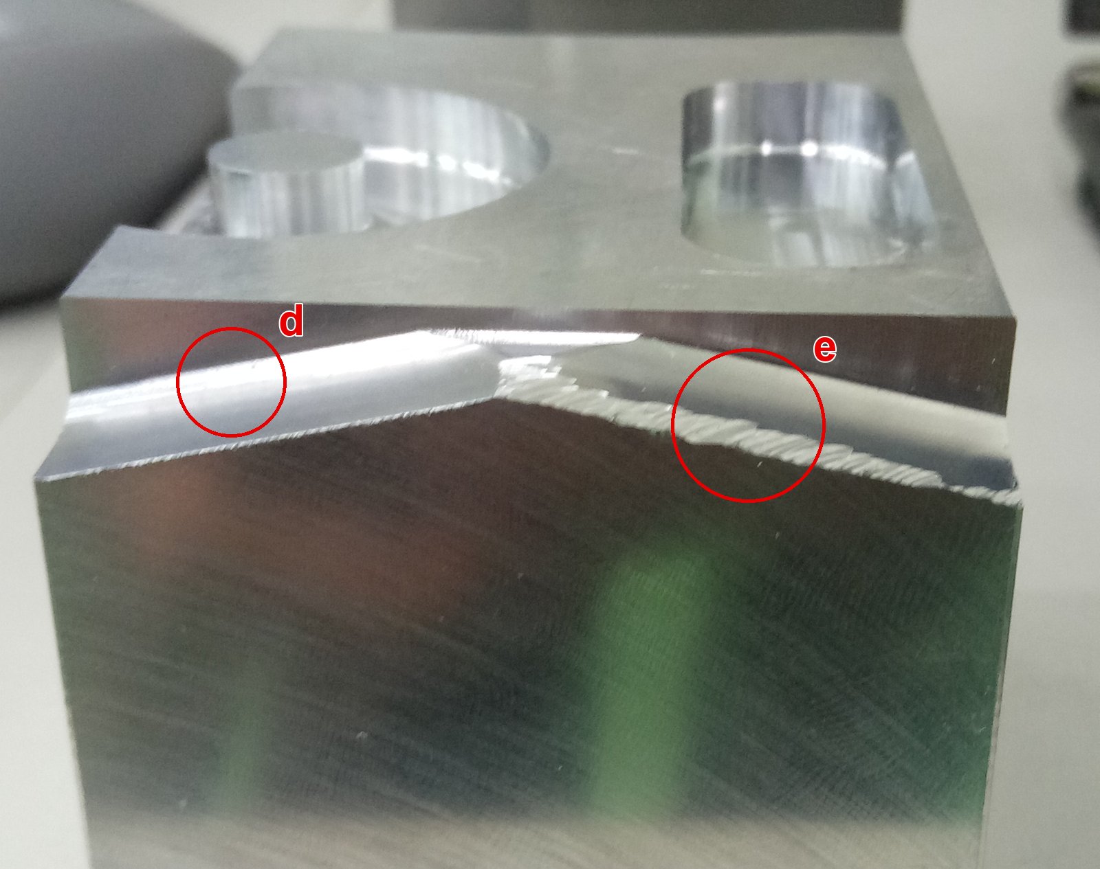
The target block from its right face (+X), photographed on 14 February 2019, the day it was cut, almost level and a little from above, cropped to the block. The front face (Y 0) is to the left and the back (Y 50) to the right; over the top face the pocket with its boss shows on the left and the slot on the right. Along the top edge runs the roof-shaped band the slope program cut: d, its front slope, bright and smooth; e, its back slope, its top edge torn into saw teeth. The red circles and letters are the agent's marks. The broad face below is the right face itself, its green and brown tints reflections, and the blurred shapes behind the block are the background. The simulation does not grow a tear; this photograph only identifies the block.
Results and benefits
The results are on Tool Marks on an Aluminium Demonstration Block: Results and Benefits, all from the plays on HiNC 3.2.57 at 0.03125 mm and one step per spindle revolution. Each part is summed up below in one sentence.
The plays
Feedback Mode took about 1.27 times as long as Ideal Mode, since each of its steps waits for the cutting force of the step before it. More.
What each mode shows
Compared with the design at 0.001 mm, the Ideal Mode floors read as the program's shape, while the Feedback Mode floors lie up to 0.9 µm below it, with the slot's marks where the photographs show them. More.
The floors
Measured on the exported blocks, the Ideal Mode floors lie at the programmed height at every vertex, and the Feedback Mode floors mostly 0.3 to 0.9 µm below it. More.
Where the marks lie
The arcs lie where the tool's deflection differs between neighbouring steps, the two lanes meet in a ridge, the slot's long walls and the boss stand about 2.5 µm proud of Ideal Mode's while the pocket's outer wall lies about 2.5 µm further out, and the slot's far wall carries a 3.91 µm step. More.
The block coloured by step
Coloured by the spindle torque of the step that cut it last, the Ideal Mode block shows smooth bands along the passes, and the Feedback Mode floors break into patches. More.
What it tells
Ideal Mode says whether the program cuts the shape, and Feedback Mode, read at 0.01 and 0.001 mm, says where the cutting force changes enough to leave a mark and how deep HiNC makes it. More.
Honest limits
- A raised strip on the boss's front, not a tool mark. In Feedback Mode the boss's wall between 273° and 276° (about X 35.4, Y 2.0, on the boss's front) stands up to 10.9 µm proud of the programmed wall, the medians of the four 1° bins being 3.1, 8.1, 8.3 and 2.3 µm; between 270° and 272° and from 277° on the medians are 0.02–0.25 µm, and Ideal Mode reads 0.01–0.04 µm there. Its cause is not known; it may be a defect in HiNC, and it is being looked into. This page does not count it as a tool mark. In the oblique views, the picture at the head of this page among them, it shows as a thin dark-blue vertical line on the boss's front; from above it cannot be seen.
- Only the places in the photographs compare. A photograph cannot measure depths of micrometres; the places were judged by eye on photographs whose perspective was not corrected; and the deflection follows the tool's stick-out and flute length, while how far the tool stood out on the day of the experiment is not recorded (the project sets 28 mm out and a 20 mm flute length). So the arcs' shape and depth are not compared.
- The product page's photographs A, B and C. Their original images are not among the experiment's photographs; this page does not say which block or which picture they show.
- The torn edge is not simulated. HiNC removes what the tool sweeps; the tear only identifies the block.
- The cutting data's force-model version is unknown. HiNC warns that the project's cutting-parameter file does not say which force-model version it was fitted under; between versions the same coefficients give forces that differ by up to about a quarter in the feed direction (Workpiece). The deflections, and the depths of the marks, follow from those forces.
- The depths are the agent's measurement. The floors' and walls' numbers come from the exported blocks on a 0.03125 mm grid, not from the Diff, whose colours agree with them.
- A checkered patch near the start hole's centre. It is in the Feedback Mode data; its cause was not looked into.
- Times from a shared server. Other agents' work ran during both plays; the times carry noise of some tens of percent.
- One tool and a plain holder. The project's only tool and its cylindrical holder; no second agent rebuilt the case.
What a reader can take to their own case
- Look for tool marks at the fine radii in Feedback Mode. At 0.01 and 0.001 mm Ideal Mode shows the program's shape and nothing else; tool marks need the cut shifted by the tool's deflection.
- Compare with the Ideal Mode result where the design is not the program's shape. It removes what the two modes share — fillets the design lacks, faces the design draws otherwise — and leaves what the deflection changes.
- Keep the detection radius near what is being looked for. Against a fine STL of the other mode's result, a radius of a few tens of micrometres finished in seconds where 1 mm had not finished after 9 minutes.
- Frame both plays on the program, not on pixels. A line of a program that cuts nothing gives the same camera in every play and on every service.
- Try the motion resolution on a shortened program. Here one step per tooth showed nearly the same marks as one per revolution for three to four times the time.
Source and licence
This case has no public source data. It is built on HiNC's own demonstration project and on photographs of an aluminium block that the same four programs cut in February 2019, in a cutting experiment run with a partner. Neither the model, the NC programs nor the project is offered, and there is no licence to give; the photographs are cropped to the block and carry no metadata. No backup copy of source files is offered, since none is published.