Tool Marks on an Aluminium Demonstration Block: Results and Benefits
The results of the aluminium demonstration block case: the two plays, what each mode shows against the design and the photographs, the floors, where the marks lie, the block coloured by step and what it tells. The case, the set-up, the dilemmas and the honest limits are on the case page.
Results and benefits
All numbers are from the plays on HiNC 3.2.57, at 0.03125 mm and one step per spindle revolution, on a shared 32-thread server.
The plays
| Ideal Mode | Feedback Mode | Ideal Mode, second play | |
|---|---|---|---|
| Steps | 16,391 | 16,391 | 16,391 |
| Run time | 1,754 s, long: the agent's own slow comparison ran beside it (dilemma 5) | 1,647 s (27.5 min) | 1,296 s (21.6 min) |
| Highest memory | 7.84 GB | 7.88 GB | 7.80 GB |
| Chip-stock truncation / deflection transformation, read back | off / off | on / on | off / off |
| Collisions, rapid moves that cut | 0, 0 | 0, 0 | 0, 0 |
Feedback Mode took about 1.27 times as long as Ideal Mode (1,647 against 1,296 s): each of its steps
waits for the cutting force of the step before it, so its steps cannot be computed overlapping.
Other agents' work ran on the server during both plays, so the times carry noise of some tens of
percent. The memory is
nearly the same. The steps per program: pocket 1,090, slot 11,068 (most of them the helical entry;
7,075 in Ideal Mode and 7,076 in Feedback Mode touch the block), side 311, slope 3,122, framing 767,
parking 33. Every play gave the same three warnings: the project's cutting-parameter file does not
say which force-model version it was fitted under (CuttingPara-PhysicsModelVersion--Missing), the
machine has no stroke limits set (StrokeLimit--Unconfigured), and the framing program's 767 steps
touch nothing (Tool-Touch--None), which is what it is for.
The trial plays of the shortened slot program, from a whole block each:
| Mode | One step per | Steps | Run time | Highest memory | Slot floor minus the programmed Z −5 (µm) |
|---|---|---|---|---|---|
| Ideal | revolution | 1,239 | 296 s | 4.55 GB | 0 at every vertex |
| Feedback | revolution | 1,239 | 366 s | 4.67 GB | −0.93 to −0.01, median −0.48 |
| Feedback | tooth | 3,365 | 1,464 s, about 9 min of it beside another comparison of the agent's | 5.80 GB | −0.89 to −0.01, median −0.48 |
What each mode shows
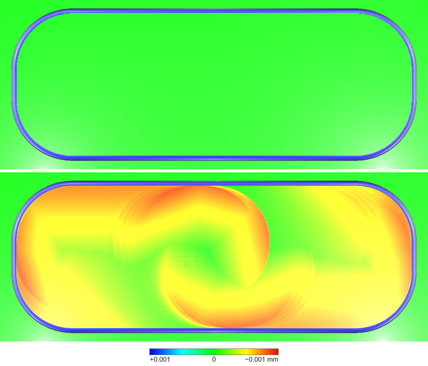
The slot from above, +X to the right, compared with the design at a visual radius of 0.001 mm: Ideal Mode above, Feedback Mode below; the bar is the same as at the head of the case page. In Ideal Mode the floor reads as green as the uncut top face round it: the program's shape. In Feedback Mode the floor is 0.01–0.90 µm below its programmed height (green where it is lowered least, orange-red where most), by a different amount from step to step, and the edges between those amounts are the marks: the arcs of the cutter's edge round the start hole in the middle and at the two ends, and the boundary between the two lanes, along the slot. The blue line round the rim in both is the wall-foot fillet; the white glow in the lower corners is the light's reflection. The small checkered patch near the start hole's centre in Feedback Mode is in the data; its cause was not looked into.
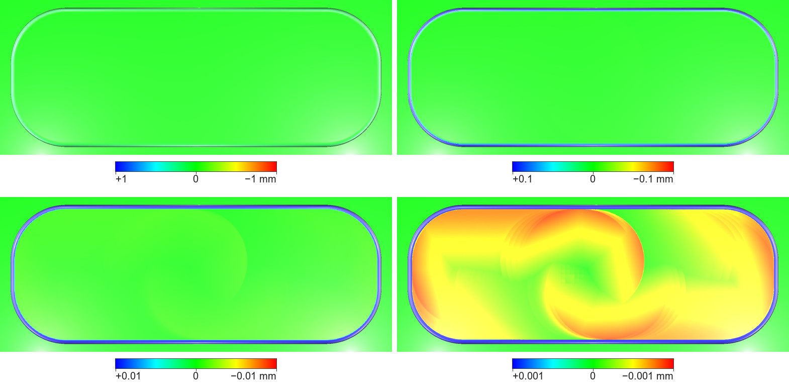
One comparison of the Feedback Mode slot with the design, read at four visual radii: 1 mm (top left), 0.1 mm (top right), 0.01 mm (bottom left) and 0.001 mm (bottom right); the bar under each panel prints its ±r. At 1 and 0.1 mm the two modes look the same. At 0.01 mm the deepest floor, 0.9 µm, is only 9 % of the colour range and shows as a faint yellow-green and the start hole's outline. At 0.001 mm the marks appear. The rim's fillet is faint at 1 mm and saturated blue from 0.1 mm down.
The slot seen from the block's front, looking down at about 56°, compared with the design at 0.001 mm, switching between Ideal Mode and Feedback Mode every second; the label at the top left names the mode in Chinese and English and the visual radius, the bar is the same as at the head of the case page, and the dark-blue band along the top is the view's background. In Ideal Mode the floor and the far wall read as the design (the wall dark green, being turned from the light); in Feedback Mode the floor carries the marks, the end walls are blue, and the far wall is blue up to X ≈ 35.5, green just right of it — the step A — and bluer again towards the +X end. The white glare in the middle of the far wall is the light's reflection; the blue line along the wall's foot is the wall-foot fillet.
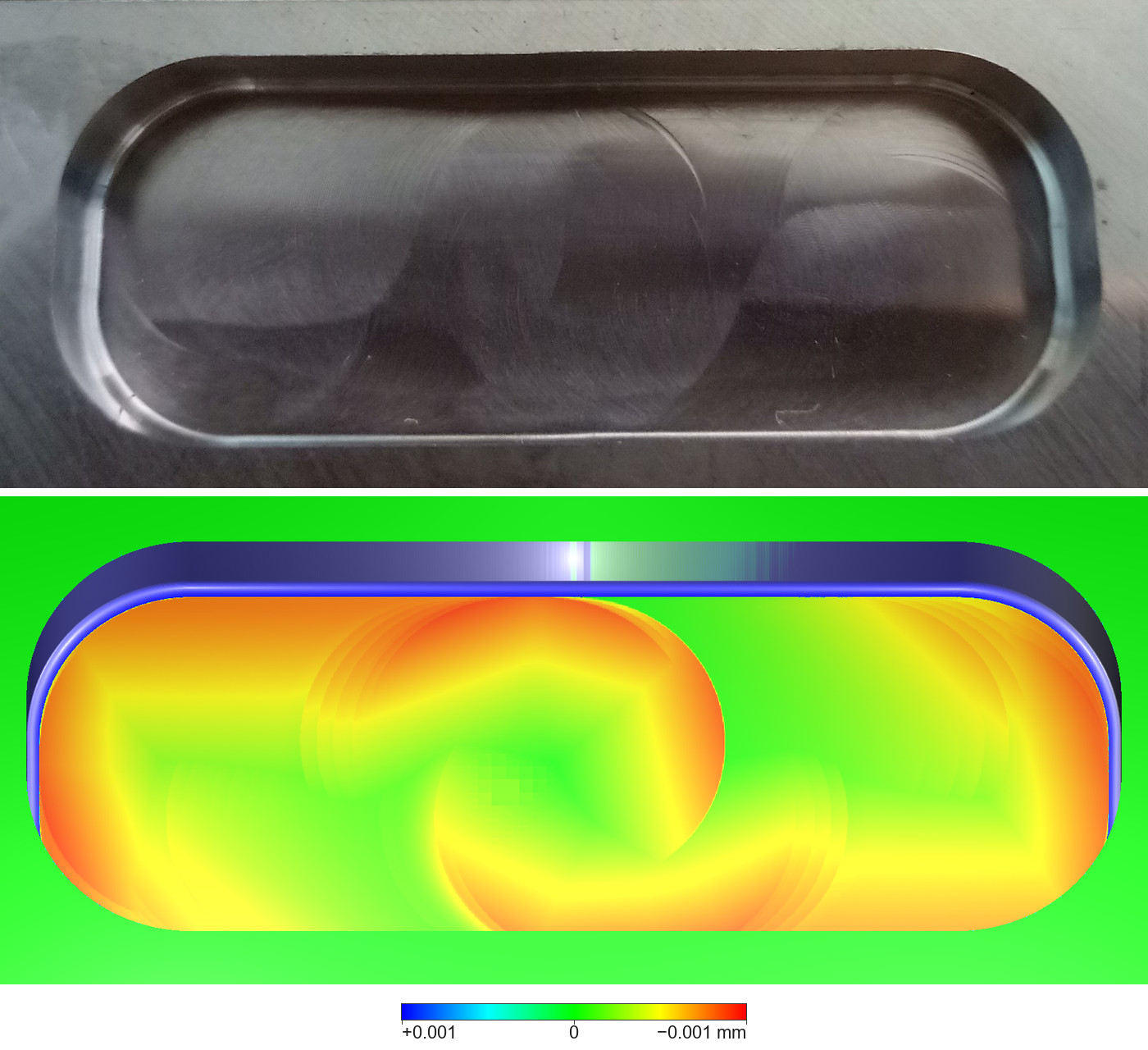
Above, the photograph of the target block's slot (18 February 2019), from the front, looking down at about 60–70° (judged by eye): two large arcs across the middle of the floor, smaller arcs in the right half and a boundary between the two lanes. Below, Feedback Mode compared with the design at 0.001 mm, looking down at about 56°: the arcs round the start hole and at the +X end lie where the photograph shows them; the far wall is blue left of X ≈ 35.5, where Feedback Mode leaves it up to 3.9 µm further into the slot, green just right of it, and bluer again towards the +X end; the white glare on the far wall is the light's reflection, and the blue line along its foot is the wall-foot fillet. Only the places compare (dilemma 2).
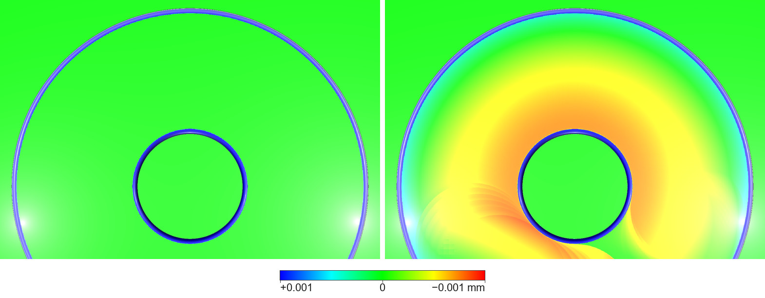
The ring-shaped pocket from above, +X to the right, the front face at the bottom, compared with the design at 0.001 mm: Ideal Mode left, Feedback Mode right. In Feedback Mode the floor runs from orange by the boss through yellow and green to cyan by the outer wall, orange lying below the programmed height and cyan above it; over the whole pocket the floor lies between 0.88 µm below and 0.34 µm above it. The arcs in front of the boss are where the cut starts and ends, and the green by the boss's lower right is the last stretch of the circle, where the floor and the boss's wall lie almost at their programmed place. The green outside the pocket and on top of the boss is the uncut top face. The blue lines round the boss and the outer wall are their wall-foot fillets; the white glows near the corners are reflections.
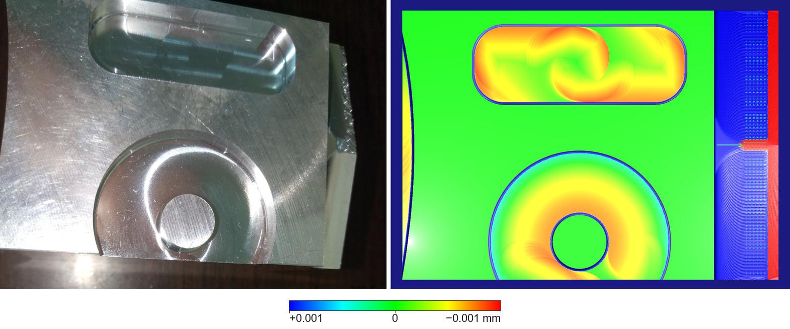
The whole block from above, +X to the right. Left, the photograph (18 February 2019): the pocket's floor shows a bright band left of the boss and the pocket's gap in the front face; along the right edge the sloped band, torn on its back half; the large arcs on the top face were left by facing the block earlier, not by these programs. Right, Feedback Mode compared with the design at 0.001 mm, on the view's dark-blue background: both floors with their marks; the top face green, and the blue line round each rim the wall-foot fillet; the sloped band blue and red, as the design is not the shape the slope program cuts; the curve at the left edge is the side face seen edge-on, the yellow strip beyond it the step the side program leaves at its foot; the white glow at the lower left is a reflection.
The floors
The agent's own measurement of the exported blocks: the flat floor's vertices at Z −5 (in the slot within 6.95 mm of its centre line, in the pocket between radius 5.55 and 16.45 mm, about three million vertices each), against the programmed height. The STL stores coordinates as 32-bit numbers, fine to 0.5 nm at this height.
| Floor height minus the programmed Z −5 (µm) | Slot | |
|---|---|---|
| Ideal Mode | 0 at every vertex | 0 at every vertex |
| Feedback Mode | −0.90 to −0.01, median −0.47; 99.8 % of the vertices lower than −0.05 | −0.88 to +0.34, median −0.38; the side by the outer wall above the programmed height |
So at 0.001 mm the Ideal Mode floors read green and the Feedback Mode floors mostly yellow to orange-red (−0.3 to −0.9 µm); at 0.01 mm the Feedback Mode floors are a faint yellow-green, at most 9 % of the colour range; at 0.1 and 1 mm both modes look the same.
Where the marks lie
The arcs of the cutter's edge. Where the tool's deflection differs between two neighbouring steps, the floor keeps an arc of radius 5.5 mm — the tool's radius of 6 mm less its corner radius — along the cutter's edge at the boundary between the two steps: at the start of each pass, at the turns at both ends, and where the width of cut changes (pass 1 leaving the start hole, pass 2 crossing it). The agent picked out the steps of the slot's straight passes and of the links between them whose tip deflection differs from the step before by 0.5 µm or more: 22 steps. The largest, with the tool centre in the programs' coordinates:
| Tool centre (X, Y), mm | Where in the slot | Difference of tip deflection from the step before (µm) |
|---|---|---|
| (48.90, 41.50) | start of pass 3 | 3.32 * |
| (21.10, 38.50) | start of pass 2 | 3.32 * |
| (34.90, 41.50) | start of pass 1 | 3.15 * |
| (35.00, 41.20) | leaving the start hole for pass 1 | 2.92 * |
| (49.00, 38.60) | turn at the +X end | 1.28 * |
| (21.00, 41.40) | turn at the −X end | 1.28 * |
| (35.7–36.7, 38.50) | pass 2 crossing the start hole, the width of cut growing from about 9 to about 10 mm, five steps | 0.54–0.59 each |
| (34.3–33.3, 41.50) | pass 1 out of the start hole, the width of cut growing from about 5 to about 9 mm, five steps | 0.57–0.84 each |
The difference is the length of the difference between the two steps' tip deflections, X and Y, as HiNC's step data gives them in the tool's running frame (Milling Physics Coordinate Systems), which turns with the tool's direction of travel. *At these six places the direction of travel turns by 90° in that step and the frame turns with it, so the value subtracts the components of two different frames: it locates the place, and does not mean the deflection changed by that much. The last two rows lie within one straight pass, where the direction does not change, and read as they are.
The boundary between the two lanes. Across the slot, sampled every 0.0625 mm, the floors of the two lanes meet in a ridge:
| Section | Ridge at | Ridge height (µm) | Lowest floor (µm), at |
|---|---|---|---|
| X 27 | Y 39.06 | −0.15 | −0.76, Y 46.75 |
| X 35 | Y 39.38 | −0.07 | −0.84, Y 46.88 |
| X 43 | Y 41.19 | −0.12 | −0.76, Y 33.19 |
The walls. Feedback Mode against Ideal Mode, the walls' vertices between Z −4.4 and −0.6, the two exported blocks subtracted on the same grid points:
| Wall | Feedback Mode against Ideal Mode |
|---|---|
| Slot, both long walls | 2.38 µm further into the slot (median), more than 3.41 µm on 1 % of the vertices, at most 9.69 µm at a point whose place was not looked up: more material left |
| Boss | 2.49 µm proud (median): more material left |
| Pocket, outer wall | 2.54 µm further out (median), 1.13 to 2.89 µm: cut deeper |
| Side face | 1.17 µm more material left (median), at most 2.86 µm |
Along the walls, the slot's in 0.5 mm bins along X and the pocket's in 5° bins round its centre, each bin the mean of its vertices. The slot's two long walls between X 33 and 37, material Feedback Mode leaves beyond Ideal Mode's wall (µm):
| X (mm) | 33.0 | 33.5 | 34.0 | 34.5 | 35.0 | 35.5 | 36.0 | 36.5 | 37.0 |
|---|---|---|---|---|---|---|---|---|---|
| Far wall (Y 47.5), A | 3.16 | 3.18 | 2.81 | 1.93 | 1.30 | 3.92 | 0.01 | 0.03 | 0.05 |
| Near wall (Y 32.5), C | 0.23 | 0.27 | 0.30 | 0.48 | 0.95 | 1.94 | 2.80 | 3.23 | 3.15 |
- The far long wall (Y 47.5), A. Between X 35.5 and 36.0 it jumps from 3.92 µm into the slot to 0.01 µm, a step of 3.91 µm, near where pass 1 (towards −X) and pass 3 (back to X 35) meet. From X 21.5 to 31.5 the wall stands steady at about 2.55 µm in; from X 36 on it starts at 0.01 µm and moves in gradually, to about 1.5–1.7 µm at X 45–48.5.
- The near long wall (Y 32.5), C. Between X 35.0 and 36.5 it moves gradually from 0.95 to 3.23 µm into the slot, with no sharp step, then falls back and stays at about 2.55 µm from X 39 on. The near wall is cut by pass 2 alone, whose width of cut grows from about 1 mm at X 34 to about 10 mm at X 36.5 (about 6 mm at X 35).
- The end walls, B. Each has a vertical line in its middle, with different amounts left on its two sides. The −X end wall is cut by the end of pass 1, the link where the tool centre moves along X 21 from Y 41.5 to 38.5, and the start of pass 2; the +X end wall by the end of pass 2, the link along X 49 and the start of pass 3. The line lies where these parts meet; which two of them meet at it was not measured part by part.
- The pocket. The pocket program starts at 270° (counted from +X, counter-clockwise; 270° faces the block's front) and runs clockwise round the boss. Most of the boss stands about 2.55 µm proud of Ideal Mode's wall; between 215° and 245°, shortly after the start, up to 3.2 µm; between 280° and 345°, before the end, only 0.03–1.8 µm. Most of the outer wall lies about 2.55 µm further out. The raised strip at 273°–276° is measured on its own (Honest limits).
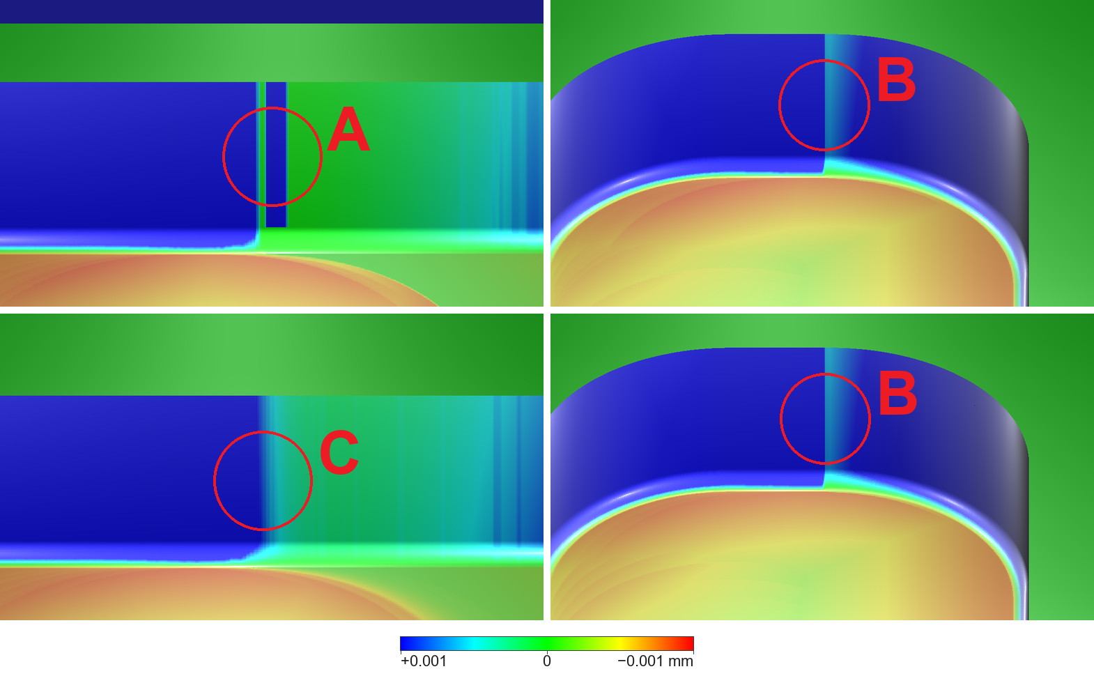
The slot's walls in Feedback Mode, compared with the Ideal Mode result at 0.001 mm; blue is material left that Ideal Mode removed, red material removed that Ideal Mode keeps; the bar is the same as at the head of the case page. Each panel, from the top: the block's top face (green band), the wall, the light green and cyan line of the wall-foot fillet, and the floor (orange, yellow and green, lower than Ideal Mode's); the dark-blue strip above panel A is the view's background. Top left, A: the far wall seen from the slot's near side, +X to the right: blue on the left, then a thin green line and a narrow blue strip at X ≈ 35.5, the step, and green to cyan with vertical streaks to the right. Top right and bottom right, B: the −X and the +X end walls, each seen from inside the slot, with a vertical line in its middle. Bottom left, C: the near wall seen from the far side, +X to the left: blue on the left, changing gradually to green and cyan with no sharp step. The red circles and letters mark the places A, B and C of HiNC's product page.
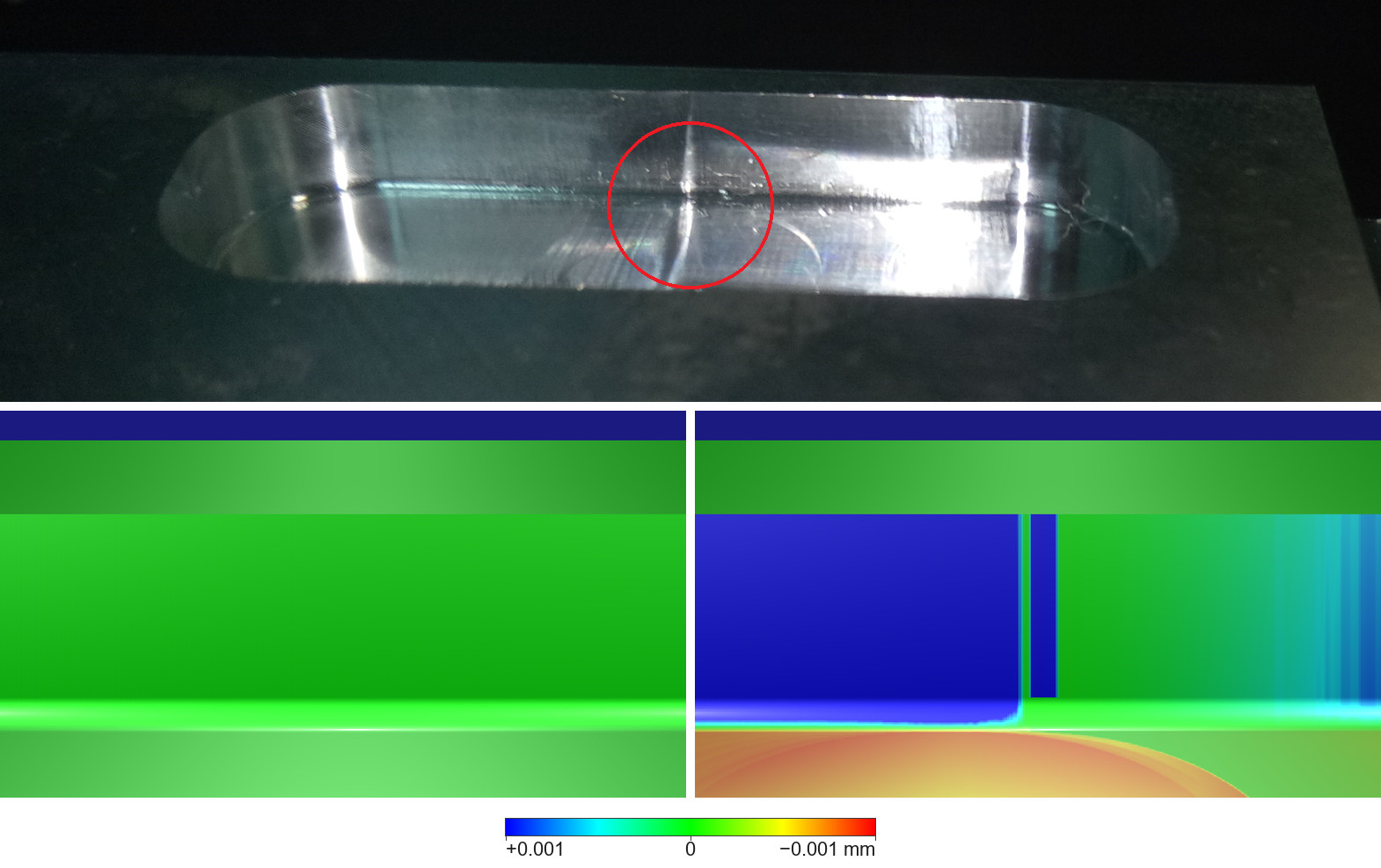
The far wall at A. Above, a photograph of the target block's slot (18 February 2019) from the front at a low angle, cropped; the red circle marks the straight mark on the far wall at X ≈ 35, near where the program's passes 1 and 3 meet; the dark line running along the wall's foot is the line b of the marked photograph under The case, the broad bright bands towards both ends are the light reflected where the wall bends into the end walls, and the curved line on the floor just right of the circle is an arc on the slot's floor. Below, the same place compared with the Ideal Mode result at 0.001 mm, on the bar of the head of the case page, the dark-blue band at the top being the view's background: Ideal Mode left, all green, as a reference compared with itself should read; Feedback Mode right, the wall as in panel A above and the floor orange to yellow, lower than Ideal Mode's.
The block coloured by step
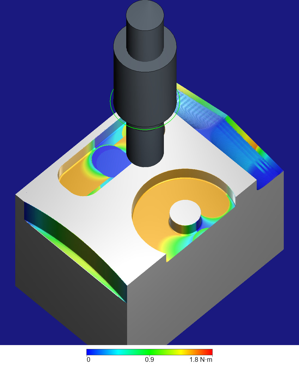
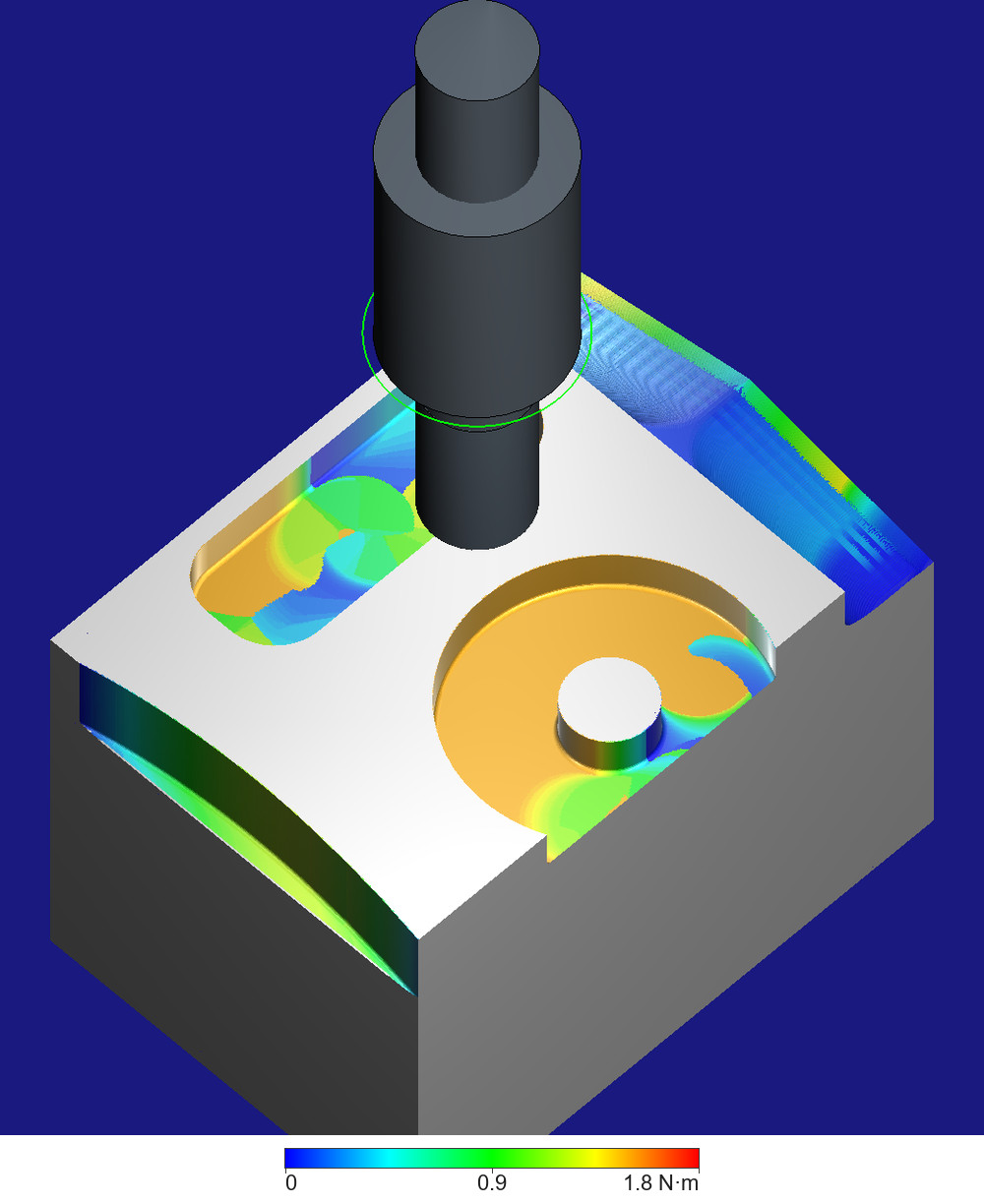
The whole block after Ideal Mode (first picture) and after Feedback Mode (second), seen at a slant from above its front-left corner before the Diff, each cut face coloured by the spindle torque of the step that cut it last, on the bar under each picture from 0 (blue) to 1.8 N·m (red). The top face and the outer faces, which no step cut, are white and grey; the dark blue round the block is the view's background. In Ideal Mode the pocket's floor and most of the slot's are orange, the full-width cuts; the slot's start hole is a blue disc, last cut by the helical entry's light steps; blue and green bands mark where each cut starts and ends; the sloped band, cut 0.68 mm at a time, is mostly blue, and the side face green to yellow. In Feedback Mode the slot's floor breaks into patches, and so does the pocket's floor in front of the boss, for the reason given under the next picture. The tool and its holder are drawn as in the picture at the head of the case page, green ring included; the machine is hidden.
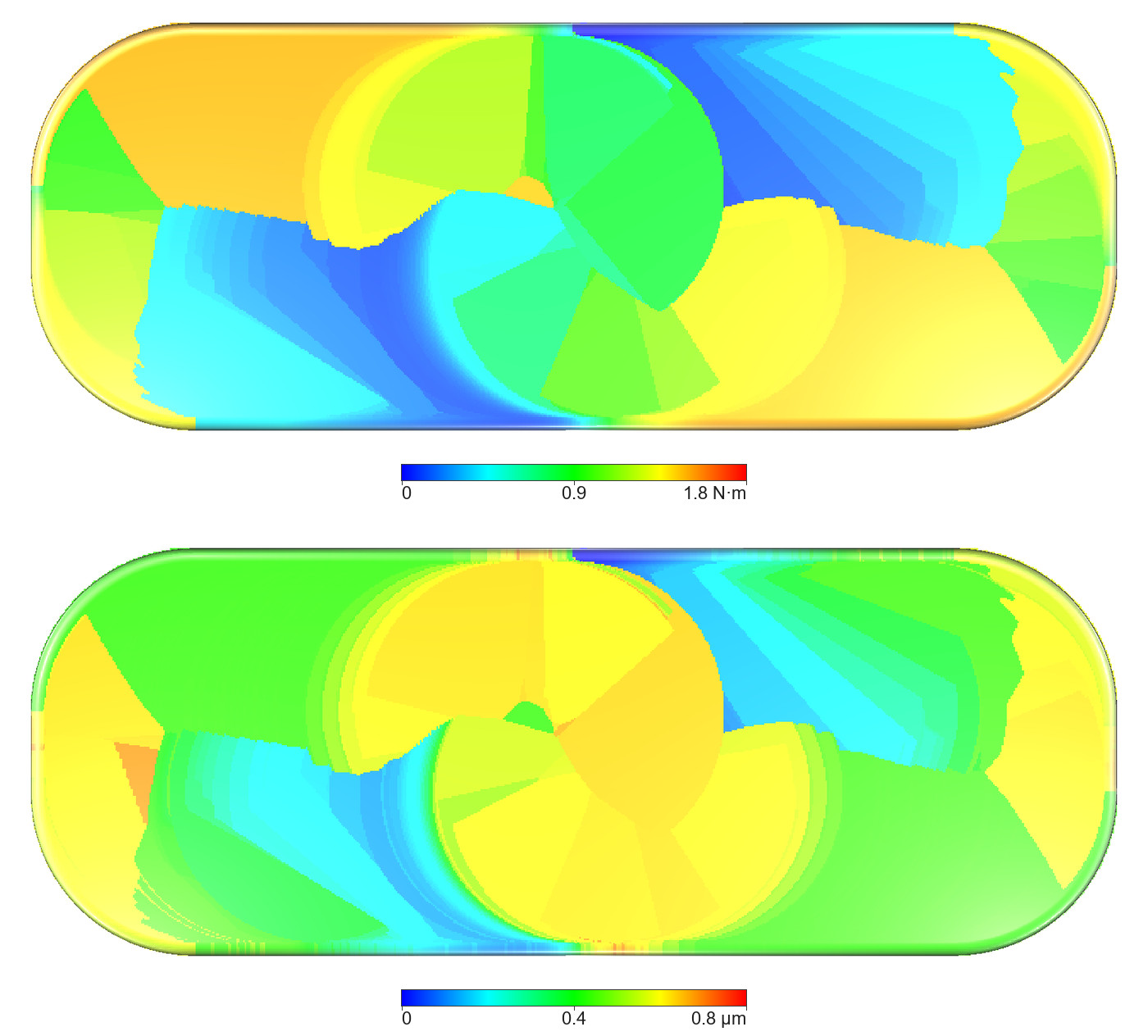
The Feedback Mode slot from above, +X to the right, before the Diff, each point coloured by a value of the step that cut it last: above, the spindle torque, 0 to 1.8 N·m; below, the re-cut depth, 0 to 0.8 µm, a simplified reading of the depth of the marks, one value per step (blue the lowest, red the highest). The floor breaks into wedges: in Feedback Mode a later step that re-cuts a sliver of floor becomes the last step there. The walls take the colour of their last step too. The white beyond the rim is the top face, which no step cut.
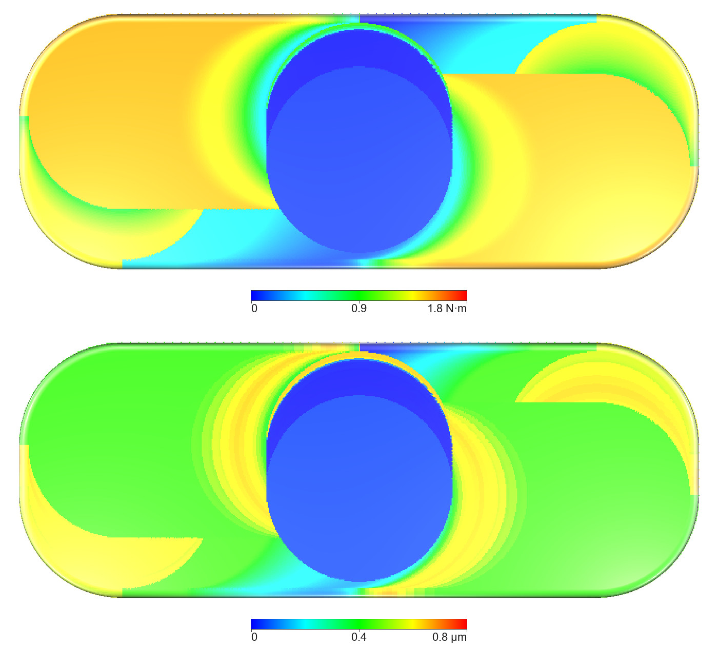
The same views after Ideal Mode, on the same scales: smooth bands along the passes and round the start hole, as in the figure of HiNC's product page; the arcs either side of the start hole are where the three passes start and end. The start hole itself is a blue disc, last cut by the helical entry's steps, each of which removes little and carries a torque near 0 (a median of about 0.06 N·m over those few thousand steps). The re-cut depth below is not 0: Ideal Mode computes each step's deflection and re-cut depth too, a median of about 0.4 µm on the three straight passes, but does not let the deflection move the cut, so its floor stays at the programmed height at every point.
The slot's steps by pass, Feedback Mode, medians; the tip deflection is in the tool's running frame, X along the feed and Z along the tool (Milling Physics Coordinate Systems):
| Pass | Width of cut (mm) | Spindle torque (N·m) | Tip deflection X, Y (µm) | Re-cut depth (µm) |
|---|---|---|---|---|
| 1 (Y 41.5, towards −X) | 12.0 | 1.50 | −0.73, +2.81 | 0.43 |
| 2 (Y 38.5, towards +X) | 6.67: about 3.3 at X 21–25, under 1 crossing the start hole, growing from X 34.5, the full 12 from X 40.5 | 0.44 (at most 1.50) | +0.61, +2.01 | 0.43 (at most 0.70) |
| 3 (Y 41.5, towards −X) | 1.53 | 0.21 (at most 0.44) | +1.20, +0.77 | 0.25 (at most 0.50) |
The spindle torque is the mean of each step's absolute torque; the tip deflection is how far the cutting force pushes the tool's tip from its programmed place; the re-cut depth is the depth HiNC computes for each step's re-cut of the floor. Ideal Mode computes the same forces and deflections step by step (pass 1: −0.73, +2.81 µm, as in Feedback Mode) but does not let them move the cut.
What it tells
For a machining engineer. Ideal Mode says whether the program cuts the shape; Feedback Mode, read at 0.01 and 0.001 mm, says where the cutting force changes enough to leave a mark and how deep HiNC makes it: under 1 µm on these floors, at the start and end of each pass, where the width of cut changes and where the passes' lanes meet, and 3.9 µm on the far wall near where two passes join. The 2019 photographs show marks at these places on the slot's floor and far wall.
For a teacher or a student. Why a mark appears where the force changes: with the cut shifted by the tool's deflection step by step, a change of deflection between two steps leaves a step in the floor along the cutter's edge, an arc; and that a wall can keep a step near where two passes meet. Also how a comparison's colour range decides what it can show: the same result is plain green at 0.1 mm and full of marks at 0.001 mm.
For someone weighing the approach. Two whole plays of 22 to 28 minutes and under 8 GB each on a shared server, Feedback Mode about 1.27 times the time of Ideal Mode; one comparison per reference and visual radius in seconds, once the detection radius was right; and photographs of the real block that put the marks in the same places.
Source and licence
This case has no public source data. It is built on HiNC's own demonstration project and on photographs of an aluminium block that the same four programs cut in February 2019, in a cutting experiment run with a partner. Neither the model, the NC programs nor the project is offered, and there is no licence to give; the photographs are cropped to the block and carry no metadata. No backup copy of source files is offered, since none is published.
See Also
- Tool Marks on an Aluminium Demonstration Block — the case these results belong to: the demonstration project, the photographs, the set-up, the dilemmas and the honest limits
- Showcase — the other cases and how a case page reads