Attaching and Building the Machine Chain
How a machine's kinematic chain gets into a project and is built there: attaching a chain file to the Machine Tool item, binding its roles, reshaping a shipped machine in the Topology column, taking the numbers from CAD or a catalogue, a machine with no model, a worked example and a machine laid on its side. Where the item is, checking what is attached and the machine's error terms are on Building Virtual Machine Tools.
Attaching a chain to a project
A chain file is not a project's machine until it is loaded onto one. The Machine Tool item's Object
Management (⋮) menu is where a chain arrives and leaves:
| Entry | What it does |
|---|---|
| Load | Picks a .MachineTool or .mt file from the project or the administrator directory and installs it as the project's chain |
| New ClMillingDevice | Attaches a CL-driven blank device instead — the one chain type that needs no file, because it has nothing to configure |
| Save As | Writes the attached chain out as a .MachineTool or .mt file, its role bindings included |
| Copy / Paste | Carry the chain between projects as XML |
| XML Mode | Shows the attached chain as XML and installs the result of an edit (Apply); Cancel leaves it as it was |
Every chain type other than the CL-driven device arrives by Load, Paste or XML. Installing one re-attaches the fixture and workpiece mounts and rebuilds the Control Tree, so the rest of the equipment follows the new machine without being touched.
Tip
Load opens on the shipped machines. This menu's picker has two roots, the project folder and
the administrator directory, and on this item it opens in the administrator directory's
Resource → MachineTool folder, where the shipped chains are: the folders CT-350.default and
Table-B1.default, each a five-axis machine with its shapes — open the folder and pick the .mt
inside — and Empty-wXYOZSt.default.mt, a bare three-axis chain with none. A chain file of your
own inside the project is one root switch away.
A Load from a file also re-points what the project saves. A chain picked from inside the project folder is remembered as a path relative to that folder. One picked from the shipped resource library is first copied into the project, under the same relative path and with its shapes, and the project refers to that copy — so editing the chain and saving the project never writes over the shared machine. Loading the same shipped machine again writes it over that copy at once, and the edits made to the copy are lost: Save As an edited machine under a name of its own before starting over from its preset. New ClMillingDevice clears that reference instead, so the fresh chain is saved inside the project rather than over the file the previous one came from. Paste and an XML apply leave the reference exactly as it was.
Roles
The Roles panel at the end of the item's panel says which element of the attached chain plays each part. Each row is a role with a dropdown over the chain's own anchors or branches and a Pick on the graph button: press it, and the next click on a matching element in the Topology column binds it.
| Role | Kind | What binds to it |
|---|---|---|
| Table Mount, Tool Mount | anchor, required | The worktable-end anchor that fixtures and workpieces attach to, and the tool-end anchor that tools attach to |
| Axis X, Axis Y, Axis Z | branch, optional, needs DynamicTranslation | The branch that carries that linear axis |
| Axis A, Axis B, Axis C | branch, optional, needs DynamicRotation | The branch that carries that rotary axis |
| Spindle | branch, optional, needs DynamicRotation | The branch that turns the tool about its own axis — the one arriving where the tool mount hangs from, turning about the tool mount's −Z through its origin. A run turns it to the spindle angle while the spindle stands (after M05, at an oriented stop); it is not an axis of the NC program |
A machine without a given axis leaves that row empty, and so does a machine whose spindle branch carries no rotation: its spindle simply does not turn on the canvas. Binding an axis or the spindle to a branch carrying the wrong transformer kind is refused, and so is binding one element to two roles, or binding an axis or the spindle to a branch marked as an error term — the rows' dropdowns leave marked branches out. Under the rows the server's checks are listed, or All checks pass.: a mount not bound, a role bound to an element outside the chain's own assembly, one element playing two roles, a mount no branch chain reaches from the root, an axis or spindle branch on the wrong transformer kind, an axis or spindle branch that is not on the chain between the table mount and the tool mount, or a spindle whose rotation does not run along the tool mount's Z axis through its origin — turning it would swing the tool, so move its Pivot onto the tool mount's origin. The error terms are checked too, each marked branch by the first check that fits: an axis or the spindle whose own branch is marked, a marked branch carrying a Dynamic Translation or Dynamic Rotation, a marked branch between the spindle branch and the tool mount, and any other marked branch that is no axis' or spindle's error term; the Fixture and Workpiece items' Roles panels report every marked branch of theirs, as neither part has error terms. Rebinding a role re-attaches the fixture and the workpiece and the canvas redraws.
The chain itself — its anchors, branches, transformers and shapes — is edited in the Topology
column: the graph draws the whole equipment with one cluster per part and the machine's role anchors
badged Machine Tool · Table Mount and Machine Tool · Tool Mount; click an anchor to rename
it, extend a new anchor from it, add a branch or give it a geometry, and click a branch to rename it
or change its transformer. Clicking the machine's cluster — titled with the chain's assembly name
followed by a Machine Tool badge — selects this item in the Control Tree, so the roles and the
graph sit side by side. A CL-driven ClMillingDevice has no editable topology or roles, and the
panel says so.
Building the chain
A machine is built by loading the shipped machine closest to it and reshaping it in the project. New ClMillingDevice is the only blank chain on offer, so a chain with X, Y, Z and rotary axes always starts from an existing machine — a loaded file, or one pasted or applied as XML.
- Load a starting point. Object Management → Load on the Machine Tool item opens on the
shipped machines, as above.
Empty-wXYOZSt.default.mtis a bare three-axis skeleton whose anchors areO,base,X,Y,Z,w,Sandt; the two folders hold a finished five-axis machine each. The load copies the machine into the project, so nothing that follows changes the shared file. - Reshape it in the Topology column. Click an anchor to rename it — the new name is committed when you press Enter or leave the field — to Extend a new anchor from it, to Add Branch to another anchor, or to delete it with a double-click on its delete button. Click a branch to rename it and pick its transformer. The card itself is described in Anchors and Roles.
- Give each axis branch a matching transformer. A linear axis is a branch carrying a Dynamic Translation, a rotary axis one carrying a Dynamic Rotation — the two kinds whose value a run varies. Every other branch — but the spindle's, which may carry a Dynamic Rotation too (step 4) — carries a static kind or No Transform; an error measured on the real machine is added afterwards, as an error term on the card of the axis or the spindle it belongs to, once that role is bound.
- Bind the roles in the Roles panel at the end of the Machine Tool item's panel, in the editor column: Table Mount to the worktable-end anchor that fixtures and workpieces connect to, Tool Mount to the tool-end anchor that tools connect to, each Axis row the machine has to the branch that drives it, and Spindle to the branch that turns the tool, when it carries a Dynamic Rotation. A shipped machine arrives with its roles already bound, and renaming an element keeps its role; deleting one gives its role up, with a notice naming the role, and that row is left to bind again.
- Give the anchors shapes. Optional: tick Geometry on an anchor's card and pick
Box3d,Cylindroid,StlFileorGeomCombination; the Transform picker under the kind moves or turns the shape into place, or leaves it as drawn with No Transform. Display color, above the shape, sets the colour that anchor's shape is drawn in; until it is set, the badge beside it reads auto. - Keep it. Saving the project keeps the edited chain in the project's own copy. For a file
another project on the same machine can load, use Object Management → Save As, which writes a
.MachineToolor.mtfile with the role bindings in it.
Names a machine file is read by
A chain in a project holds its roles by identity: an anchor or a branch keeps its role whatever it is renamed to, and Save As writes the bindings into the file, so a file saved that way loads with the same bindings whatever its elements are called. A machine tool file that records no roles — the shipped machines, and files written by earlier releases — takes them from the names of its anchors and branches as it loads, and a file saved with its Table Mount or Tool Mount unbound looks for that mount by name the same way. For such a file the names below are not labels but what makes the machine work at all:
- The motion axes are named on the branches. A branch named
X,YorZis taken as that linear axis, one namedA,BorCas that rotary axis. Use each keyword at most once — a machine without a given axis simply has no branch carrying that keyword. - The transformer kind is read with the name. A branch named
X,YorZmust carry a Dynamic Translation, and one namedA,BorCa Dynamic Rotation. A branch correctly named but left on a static transformer is bound to its axis row yet contributes no axis — the Roles panel flags it under the rows — and the machine ends up with one fewer axis than it looks like it has. - The end anchors are
wandt.w, the worktable-end anchor, is taken as the Table Mount, andt, the tool-end anchor, as the Tool Mount. A machine file missing either still loads, with a message for each end anchor it lacks, but it cannot move: simulating it stops with a message naming the missing keyword, the worktable end first. Oandbasename the ground anchor and the machine base. They bind no role, but the collision pairs below leave them out only when they are spelled exactly.- The spindle is found by place, not by name. The branch arriving at the anchor the tool mount
hangs from —
Son the shipped machines — is taken as the Spindle when it carries a Dynamic Rotation turning about the tool mount's −Z through its origin, whatever the branch is called. A spindle branch on No Transform, or on a static offset, is no spindle: the machine plays as it did, its spindle not turned on the canvas. A rotation that misses the tool axis is not taken either, and the load says so, as turning it would swing the tool around.
Important
Spell every keyword exactly as written. The motion axes are upper-case X, Y, Z, A, B,
C; the ground anchor is upper-case O; and the base and the two end anchors are lower-case
base, t and w. The exact spelling is always found first. When no anchor or branch carries it
but exactly one differs from it only in letter case, the machine still takes that one, and the load
reports it: The machine tool takes the anchor [W] as its end anchor ‘w’, a name it matches only
ignoring letter case; rename it to ‘w’. When several do, none is taken, and the load names them.
An end anchor nothing matches leaves the machine without it — The machine tool has no end anchor
‘w’: no anchor carries that name. — and its generated collision pairs are skipped. O and base
get no such tolerance: they are only dropped from the collision walk below when spelled exactly.
Branch direction is free: the motion, the axis keywords and the default collision pairs all read a
branch the same way round. Pointing every branch away from the ground anchor is a readability
convention — it makes the structure read outwards, ground → base → motion axes → the t and w end
anchors. On an axis branch, direction also decides which side of the axis its
error term goes on.
The names also decide what can collide with what. A machine file asking for its collision pairs
to be generated is answered by walking the chain twice, from the root anchor — O on the shipped
machines — to the tool mount and to the table mount. That walk needs both end anchors, so a machine
missing one loads without its generated pairs, with a message saying so; a file that lists its
collision pairs explicitly keeps them. Either way every run on the machine stops at its start,
naming the missing end anchor.
Everything named on the way becomes a collidable component; the two end anchors the machine took,
whatever their spelling, and O and base are dropped from both walks, the tool holder, cutter shank and cutter flute are added to the tool side and the
fixture and workpiece to the table side, and every pair across the two sides is generated except
workpiece against cutter flute — that one is the cut, not a collision.
Where the numbers come from
The most convenient approach is to assemble the machine in CAD, position the moving elements at the machine origin — the position at which every machine coordinate reads zero, generally the home position — and then:
- Export the main components as individual STL files from that one coordinate system, and set each into its anchor.
- Measure, in the same CAD coordinate system, the tool-end anchor, the worktable-end anchor and a point on each rotary axis' pivot, and enter those coordinates into the topology.
- Expect the axis directions from the base to the worktable end to come out negative. That is relative motion rather than a mistake: moving the table one way moves the tool the other way through the chain.
- Keep these as the design values. An error measured on the real machine — a squareness, a rotary axis' pivot offset — does not go into them: it is added as an error term on the card of the axis it belongs to.
Keep the meshes coarse. A machine carrying too much mesh is slower to open and slower to check for collisions, so export the components at the resolution a picture of the machine needs rather than at the resolution CAD produced them at.
With no CAD assembly to measure, the catalogue is enough — see A machine with no model below.
A machine with no model
A machine that is neither in the resource library nor available as a CAD assembly can still be
simulated, with a chain that carries no shapes. What a program cuts depends on the axes, their
directions and the work offsets, not on what the machine looks like, so a shapeless chain gives up
only the drawing of the machine and collisions against its body. The holder, the cutter shank and
the flute are still checked against the fixture, and the holder and the shank against the stock (the
flute against the stock is the cut, and is checked only before the program gives the spindle a
speed), because those
collision pairs come from the chain's names rather than from its shapes. Before 3.2.42 the pairs
against the stock were generated but not evaluated — the running workpiece was never handed to the
collision check, so a holder or shank that entered the stock raised no message, and the
Showcase cases checked that clearance from the geometry instead; from 3.2.42
the engine evaluates them and reports Collided(Workpiece,ToolHolder) and
Collided(Workpiece,CutterShank).
The catalogue supplies the rest: the travel of each axis, which axes the table carries and which the head carries, and the spindle-nose-to-table distance. The figures below are for a machine with 800 × 500 × 500 mm of travel whose spindle nose reaches from 600 mm down to 100 mm above the table.
- Lay out the axes. A vertical machining centre whose table carries X and Y and whose head
carries Z is
[O][Y][X][w];[O][Z][S][t]in Machine Chain Code, with the table-side axes pointing negative —(-1, 0, 0)and(0, -1, 0)— and Z positive,(0, 0, 1). An axis that the column or the head carries goes on thetside instead, pointing positive. The resource library'sMachineToolfolder ships a shapeless three-axis chain with the same axes on the same sides and pointing the same ways,Empty-wXYOZSt.default.mt—[O][base][X][Y][w];[base][Z][S][t], X stacked under Y, which makes no difference for linear axes — with its tool end 1000 mm above its worktable end. Load it on the Machine Tool item as above: it is usable as it stands when the work offsets are typed in from the machine, and a structure to reshape in the Topology column for another layout or for the other direction in step 3, leaving every anchor without a shape. - Treat the tool-end anchor as the spindle gauge line.
tis where the tool holder seats, and a tool's length offset (H) runs from there to the tip, so the chain carries no tool length of its own — the tool assembly adds it. - Place the two ends for the direction the work offsets come from. The two directions are
Program Zero Alignment.
- Work offsets typed in from the machine. The part is placed so that program zero meets them, and that placement absorbs both end offsets, so on a machine with no shapes they change nothing about the cut. Any plausible placement does, such as the one below. To check the placement, press P0 on a work-offset row the program does not use and compare it with the typed row; M0 returns the spare row to machine zero afterwards.
- Work offsets written from the model with P0. Now the two ends decide where machine zero lies
relative to the part, and so every offset P0 writes. A run starts at the home position —
machine zero unless Home / G28 Reference says otherwise — and a tool change sends Z to its
tool-change position, 0 unless Tool-Change Position says otherwise,
so
thas to stand abovewby more than the fixture, the stock and the longest tool stacked together. With the two ends at one point the tool hangs through the part at home, and the first rapid after the tool change drags it through the stock: a rapid-cut warning is raised, but the material is gone for the rest of the run. For the machine above, a static translation of(-400, -250, -600)on the branch arriving atw, against none on the branch arriving att, puts the table centre under the middle of the X and Y travel and the table top 600 mm below the tool end at home — the largest nose-to-table distance the catalogue gives. The shippedEmpty-wXYOZSt.default.mtis not such a chain: its branch arriving attalready carries(0, 0, 1000), so the same placement there is(-400, -250, 400)on the branch arriving atw. Left at-600, the table sits 1600 mm below the tool end, and every Z that P0 writes lies about 1000 mm beyond the Z travel of step 4.
- Enter the travel the way the controller reads it. On the common layout where every axis reads 0 at home and negative across its travel, this machine is X −800 to 0, Y −500 to 0 and Z −500 to 0, entered as − Limit and + Limit on the controller's Machine Limits (Stroke) leaf. Rapid Feedrates, Home / G28 Reference and Tool-Change Position sit beside it — see Controller. Read the machine's own machine-coordinate display rather than assume the layout; a machine whose axes read positive across their travel takes those numbers instead.
- Check the end anchors after a load. A machine tool file of your own is loaded the same way: put it in the project folder — with the File Explorer's Upload, for one on your own computer — and pick it with the Machine Tool item's Load from the project root. The load's own notice says nothing about the anchors: an end anchor the machine lacks or carries in the wrong letter case is written to the service's log — open the Log Viewer from the Help menu. A missing one also shows at once in the Roles panel, as a Table Mount or Tool Mount row left empty with Not bound; the mechanism needs this role. under the list, and is reported again among the messages of the next project load once the project is saved.
- Check the axes the chain actually carries. The controller's per-axis rows list X, Y and Z on every brand before any chain is attached, so a missing linear axis does not show there. Read the Roles panel instead: each axis the machine has is an Axis row bound to a branch, and an empty row is an axis the machine does not have. A branch that should drive an axis but was left on a static transformer drives nothing: taken by its name, it is flagged under the rows, and it cannot be bound to a row by hand until its transformer is changed — in the Topology column, click the branch and pick Dynamic Translation or Dynamic Rotation.
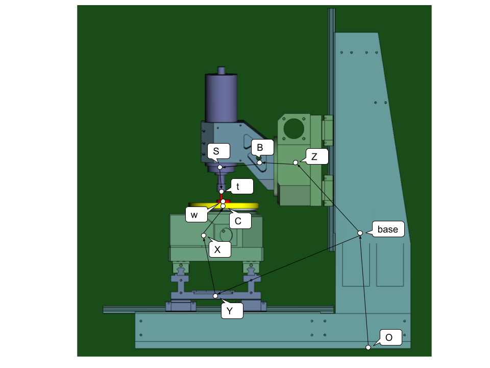
Example: a small five-axis vertical milling machine
A worked example, complete with its STLs: B1.zip. The same machine ships
as the Table-B1.default preset, so Load on the Machine Tool item opens it in a project as it
stands.
The machine it describes:
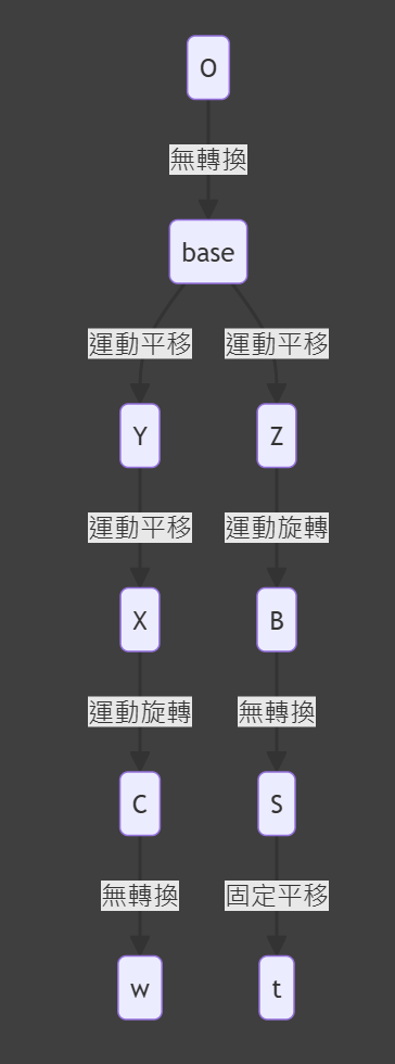
And the topology those anchors and branches form, as the Topology column draws the machine's cluster once the preset is loaded — each branch labelled with its transformer kind, after its name where it has one:
Laying a machine on its side
A horizontal machine is built exactly like a vertical one and then laid down:
- Create the topology from the machine's own axis coordinates.
- On the branch between the ground anchor and the machine base, set a rotation of 180 degrees about a normalized axis direction of (0, 1, 1).
A machine tool file can also carry this same connectivity as a short bracket notation for hand-editing the XML — the grammar is Machine Chain Code.
See Also
- Building Virtual Machine Tools — where the Machine Tool item is, what is attached, and the error terms an axis or the spindle can carry
- Anchors and Roles — the Topology column's anchor and branch card the steps above are performed in, and placing the fixture, workpiece and tool onto the chain built here
- Machine Chain Code — the bracket notation for the structure built here, and what it cannot express
- File Explorer — the browser the Object Management Load and Save As open, and where a chain file can be read or edited as text