The NUMISHEET 2025 T-Node Draw Die with the Spindle 0.01° out of Tram: Where the Two D10 Finishing Cutters Meet, the Cavity Walls Carry a 5.2 µm Step, Too Deep on One Wall and Material Left on the Other
The NUMISHEET 2025 industrial benchmark publishes the top surface of a deep-drawn part, the T-Node. In a product case of this Showcase that has no page of its own yet, an AI agent derived from that surface alone a lower draw die, the cavity and the binder face in a 320 × 350 × 150 mm block, wrote its four Fanuc programs as its own CAM and accepted the die in HiNC at 0.25 mm. Four cutters finish it: T1, a D32 R5 end mill with round inserts, face-mills the binder face and roughs; T2, a D16 ball, semi-finishes; and two D10 balls share the finishing by height, T4 at 35 mm stick-out above a tip height of z −25 and T3 at 65 mm below it. The base case split the finishing that way to hold down the long-neck ball's deflection; the price is 30 mm of difference in length between the two finishing cutters.
This page gives the case's three-axis machine one geometric error: the spindle housing tilted against
the Z travel by 0.01° in the XZ plane, 52.36 µm per 300 mm, a spindle head due for re-tramming. It sits
on one marked error term directly upstream of the spindle
branch. X and Y are touched off with T4, all four cutters take their length through G43, and not one
character of the four programs was changed. The whole die and a trimmed window were each played three
times at 0.25 mm on a HiNC 3.2.46 development build with error-term branches:
- Error terms off: the nominal run, whose cut is the ideal geometry of every comparison.
- Error terms on, marked: the controller does not know that the spindle is tilted, as on a machine whose spindle was never re-trammed. The programs are plain three-axis, which cut the error in whether it is marked or not, so no unmarked run was played.
- Error terms off again, with a Diff: the control, for the noise floor.
What came out:
- The tool tip. One constant per cutter, set by its length: in X, T1 −7.853982, T2 −6.108652, T4 −0.872665 and T3 −6.108652 µm, equal to the prediction (120 − L)·sin θ in every printed digit. On all 1,443,493 cutting steps of the whole die the tip lies on the prediction within 3.82 × 10⁻¹⁴ mm in each component, and the machine coordinates of the runs with the error on and off are the same bit for bit.
- The seam. T3's ball centre moves 30 mm × sin θ = 5.24 µm further than T4's. Below the seam, where T3 finishes, the left outer wall, which faces +X, is cut 5.18 µm too deep (median; predicted 5.22), and the right closing wall, which faces −X, keeps 5.15 µm of material (predicted 5.15). The faces T4 finishes read 0.00 µm (312,709 vertices, at most 0.077 µm, a search value and so an upper bound). One seam is too deep on one wall and keeps material on the other, and the step is not at the tip split z −25 but higher up the walls, at z −19.63 on the left outer wall and z −21.58 on the right closing wall: a ball meets a steep wall with its side, above its tip.
- The binder face. The tilted flat bottom of the D32 digs into the binder face, which only T1 face-milled, with its heel: median −1.61 µm (predicted −1.60), in rows 18.9 mm apart, −1.84 µm at the row centres and −0.89 µm between them; 99.78 % of 1,381 bins 0.25 mm wide lie in the model band. That band takes in the 1.05 mm the tool moves per spindle turn, which the analysis added; against the row model written before the play alone (±0.05 µm) it is 2.03 % (28 bins).
- The control. All 2,425,284 vertices within ±0.3 µm, at most 5.1 × 10⁻¹⁰ mm; the per-step series equal the nominal run's bit for bit.
- What was not expected. 18 vertices, measured exactly, read +8.01 to +12.67 µm, more than the 5.24 µm this error can move a finished face; their cause was not found (dilemma 7).
- The size. At a typical acceptance value of 0.003° the same formula gives a 1.57 µm step (scaled, not played). In the base case's acceptance, T3's own deflection has a median of 12.6 µm and a maximum of 132 µm over the whole die; the 0.01° step is 41.6 % and 3.97 % of them.
- The cost, on a shared 32-thread server: 2,037,526 steps, 3,258.1–3,488.2 s and a VmHWM of 9.68–13.01 GiB per whole-die run; the six runs together 13,923.4 s.
Everything here is simulated; no part was cut.
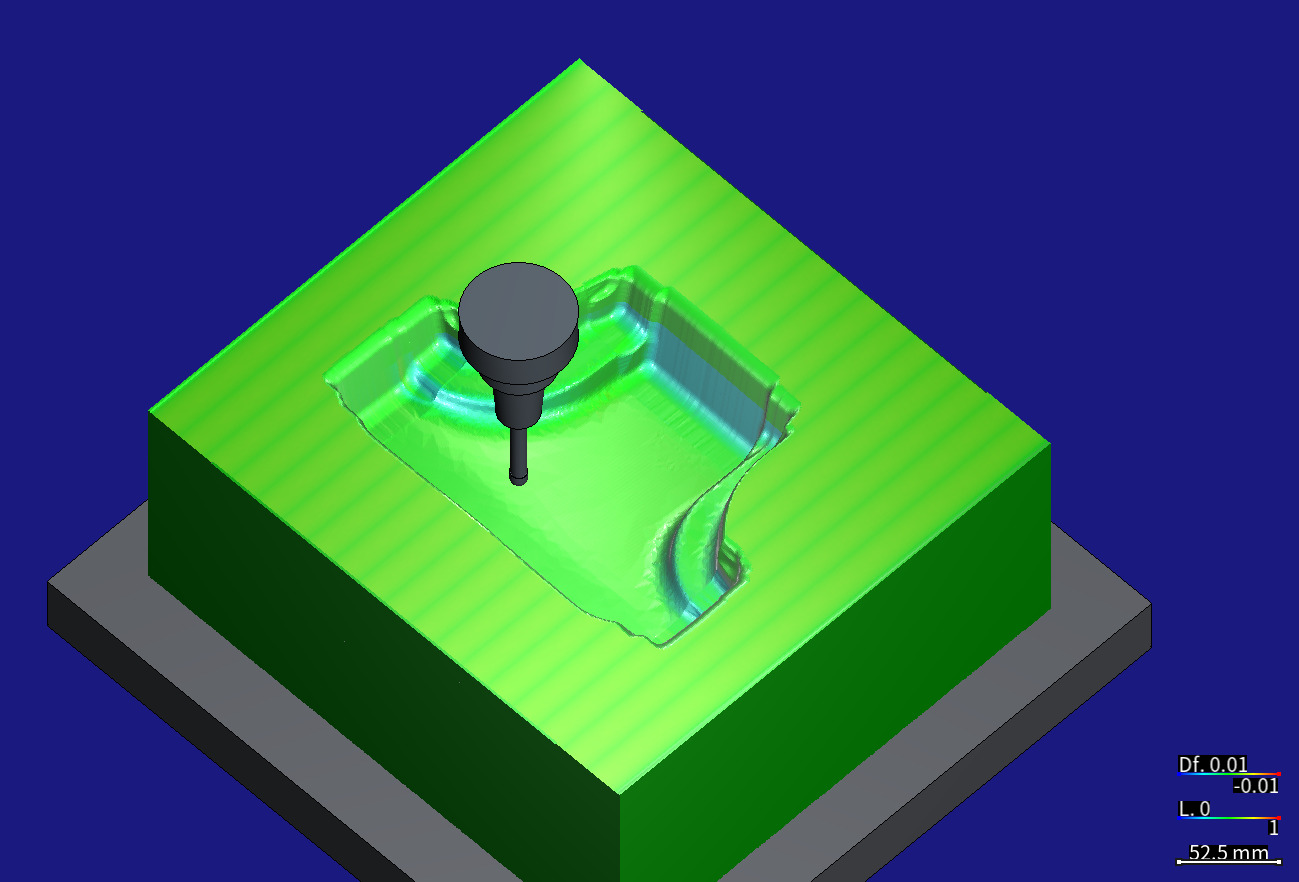
The die the run with the error terms on (marked) cut, put back on the canvas with its Diff (from above
on the −X side). The parking program pose/pose-t3-above.nc stops T3, the D10 long-neck ball at 65 mm
stick-out, and its BT40 shrink-fit holder above the cavity at (X −60, Y 0, Z 10); it only moves and
cuts nothing. The right closing wall faces the camera (it faces −X), and its lower part is blue-green,
material left; the binder face carries faint stripes along X. Diff colour scale ±0.01 mm (red = cut too
deep, blue = material left, green = 0, both signs weighted alike); 0.25 mm grid; a HiNC 3.2.46
development build with error-term branches.
| The whole die at 0.25 mm on a HiNC 3.2.46 development build with error-term branches, 0.01° | Predicted | Measured |
|---|---|---|
| Tip offset in X, T1 / T2 / T4 / T3 (µm) | −7.853982 / −6.108652 / −0.872665 / −6.108652 | the same in every printed digit |
| Tip minus the nominal tip minus the prediction, 1,443,493 cutting steps | 0 (the plan allowed 10⁻⁹ mm) | at most 3.82 × 10⁻¹⁴ mm per component |
| Machine coordinates, on against nominal | the same | the same at every step |
| Faces T4 finishes (cavity, z −18…−0.05), median | 0 | 0.000 µm |
| Left outer wall, lower part (faces +X, T3), median | −5.219 µm | −5.177 µm |
| Right closing wall, lower part (faces −X, T3), median | +5.149 µm | +5.148 µm |
| Step height, left outer wall / right closing wall | 5.22 / 5.15 µm | 5.23 / 5.15 µm |
| Step position on the wall, left / right | z −20.1 / −21.1 (design) | z −19.63 / −21.58 |
| Binder face (T1), median | −1.595 µm | −1.612 µm |
| Control against nominal, every vertex | at least 99 % within ±0.3 µm | 100 %, at most 5.1 × 10⁻¹⁰ mm |
| Server time / peak memory of a whole-die run | — | 3,258.1–3,488.2 s / 9.68–13.01 GiB |
The case
The base case, a product case of this Showcase without a page of its own yet (source and licence below), records how the agent made one feasible lower draw die for the benchmark part:
- from the target part's top surface, the only geometry the benchmark gives, it derived the cavity's die face and the binder face;
- acting as CAM, it wrote four programs and built the project through HiNC's web API;
- it accepted the whole die at 0.25 mm. That acceptance, with physics on and dated 2026-11-14, passed four of its six criteria: the long-neck D10 (T3) bends up to 132 µm with a median of 12.6 µm, so the force and deflection criterion failed, and another failed on the continuous power ratio of three single steps of T1.
Its machine was built as designed, with no error. This page puts a spindle tilt into the same machine to answer one question: with one touch-off, what does one tilt do to each of the four cutters, and where on the die does it show? What the agent was given:
- The accepted project and its programs.
- The whole die: four programs, played in the order T1, T2, T4, T3:
NC/T1-rough.nc(18,380 lines),NC/T2-semi.nc(134,751),NC/T4-finish-upper.nc(240,296) andNC/T3-finish-deep.nc(209,466). - The trimmed case: four programs
NC/trim-*.nc(5,847 / 31,010 / 39,128 / 39,210 lines) on the evaluation window x 20–100, y −90 to −10, which holds the right closing wall's upper and lower parts across the seam, the floor of the deep end and a stretch of binder face cut only by face milling (the binder strip that is judged lies outside the evaluation window, at x 102–125; see the trimmed case below). T2's window is 15 mm larger and T1's 30 mm, so that every cutter meets in the window the stock the cutter before it left in the whole die. - Fanuc,
G54(−500, −260, −410) withG43 Hn. The tool lengths come from the tool library (holder plus stick-out): H1 165, H2 155, H3 155, H4 125 mm. - Plain three-axis programs: no
G43.4,G68,G68.2,M128orTRAORI, and no CL playback. - T4 and T3 split at the tip height z −25, each running 0.5 mm past it, so both cut the band z −25.5 to −24.5.
- The program frame (
G54) is the die's frame: the block's centre, with the binder face at z 0.
- The whole die: four programs, played in the order T1, T2, T4, T3:
- The machine. The case's own copy of
Empty-wXYOZSt.default.mt: the table moves in X and Y, the head in Z; the spindle branchNewAnchor-006(Z→S, a Dynamic Rotation about (0, 0, −1) with its pivot at (0, 0, 1000)) carries the spindle role. The machine has no shapes. - HiNC's error terms. An axis or the spindle of the machine chain can be given an error term, a
static branch of its own just before the axis's branch, marked as an error term: it carries a measured
error rather than part of the design. The controller (
XyzabcSolver, which turns NC into machine coordinates) solves on the nominal chain, taking the marked branches as absent; while the project's Enable Error Terms switch is on, the simulated machine moves, cuts and checks collisions with them. So the error is cut into the part, as on a real machine whose controller does not know it. Each step's machine coordinates are the same with the switch on and off; the tool tip, the cut and the collisions differ. Without RTCP or a tilted working plane, every error in the chain is cut into the part, marked or not (What a mark changes). - Touch-off and P0. HiNC's P0 measures program zero on the nominal chain. A touch-off on a real
machine takes the constant shift the error causes at the touch-off pose into
G54(Work offsets on a machine with error terms). - A placement rule. HiNC's product owner ruled on 2026-10-06 that an error term goes only directly
upstream of a role branch, an axis X … C or the spindle, with one anchor for each error, named
<axis>err. - The request. HiNC's product owner asked for error-term showcases built on earlier cases, product cases and paper cases alike, with the heavy runs on a shared server.
What nothing states:
- Which error. The task description the designer agent received suggested a rotation inserted before the Z axis, expecting each cutter to move by a different amount; on this machine that leaves no step (dilemma 1).
- Where the touch-off is and where the pivot goes, so that
G54need not change (dilemma 2). - How large. A real size is small, a magnified one is not real (dilemma 3).
- At which height on the wall the step appears: not at the tip split z −25 (dilemma 4).
- Whether a 0.25 mm grid reads a binder face 1–2 µm deep, and whether the step per spindle turn leaves its own mark on it (dilemma 5).
What is new here:
- One error, four offsets. A spindle tilt moves each tip by its distance from the touch-off reference, and a touch-off can zero only one cutter; HiNC's per-step tool tip prints each cutter's constant offset.
- Where the two finishing cutters meet. The same seam is cut too deep on the wall facing +X and keeps material on the wall facing −X.
- The heel of a flat-bottomed cutter. The face mill's flat bottom tilts with the spindle, one side lower than the tip, and cuts a shallow hollow along every facing row of the binder face.
What the agent built
Each value is marked read (from the base case or a document), derived (computed from what was read) or chosen (the agent's or the plan's decision).
| Value | Source | |
|---|---|---|
| Meaning | The spindle housing, and with it the spindle axis, is tilted against the Z travel by θ in the XZ plane; the Z travel itself is straight and stays square to XY. Only the tool axis tilts, so a point further along the tool axis from the touch-off reference moves further sideways | chosen |
| Where | SpindleTram: Z→NewAnchor-006err, directly upstream of the spindle branch NewAnchor-006; a Static Rotation about (0, 1, 0), marked as an error term |
chosen: where the owner's ruling puts it; the manual places a three-axis machine's spindle-housing tilt between Z and the spindle branch |
| Value | 0.01°: sin θ = 1.745 × 10⁻⁴ (174.53 µrad), 52.36 µm per 300 mm | chosen: the plan reads “a spindle head due for re-tramming; a typical acceptance value is about 0.003° (15.7 µm per 300 mm)” (dilemma 3) |
| Pivot | (0, 0, 880) in the frame of the anchor Z: T4's ball centre |
derived (dilemma 2) |
| Work offset | G54 (−500, −260, −410) as in the base case; nothing typed in |
derived: the offset at the touch-off reference is 0 |
The chain, read back after the build.
- Table side
O→base→X→Y→w, tool sidebase→Z→NewAnchor-006err→S→t. SpindleTramruns fromZto the new anchorNewAnchor-006err, and its values read back as requested.- The spindle branch
NewAnchor-006now runs fromNewAnchor-006errtoS, with its Dynamic Rotation about (0, 0, −1) and its pivot (0, 0, 1000) unchanged; it still carries the spindle role, and the branch has a new guid. NewAnchor-001,X,Y,Z,NewAnchor-005andtooling-locationare unchanged.NewAnchor-006errhas no shape and takes part in no collision check.
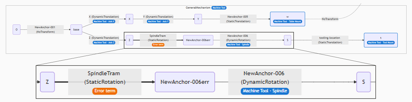
The machine-tool cluster (GeneralMechanism) in the Topology column of the Equipment page. Directly
upstream of the spindle branch NewAnchor-006 there is a new anchor, NewAnchor-006err;
SpindleTram (Z→NewAnchor-006err, a Static Rotation of 0.01° about (0, 1, 0) with its pivot at
(0, 0, 880) mm) is drawn bold with the orange Error term badge, and NewAnchor-006 is still the
spindle. Below, the stretch from Z to S of the same capture, magnified twice. A HiNC 3.2.46
development build with error-term branches, English interface.
How far the tips and the ball centres move: the prediction the plan and the design wrote before the
play. In the frame of the anchor Z:
- The anchor
Zisbasemoved by MC.Z along +z with no rotation, so its axes point the way the program axes do. The spindle axis lies at its x = y = 0;tooling-locationputs the tool mount t at (0, 0, 1000), the tool hangs down along −z, and its tip is at (0, 0, 1000 − L). - A check of the chain: with
G54andG43 H= L, MC.Z = Z_prog − 410 + L, so the tip stands at the height MC.Z + 1000 − L = Z_prog + 590 inbase, whatever the tool length. - The touch-off reference: X and Y are touched off with T4 against the block's sides, and a ball touches with its equator, so the reference is T4's ball centre, (0, 0, 1000 − 125 + 5) = (0, 0, 880). At the touch-off pose (T4 at program zero, MC (−500, −260, −285)) it stands at program (0, 0, 5).
- A rotation by θ about (0, 1, 0) with its pivot at the reference moves a point on the tool axis that lies v above it (below it when v is negative) by δ(v) = (v·sin θ, 0, −v·(1 − cos θ)), with v = 120 − L + s, where s is the point's height above the tip.
| Cutter | Tool length L (holder + stick-out) | v of the tip | Tip ΔX | v of the ball centre | Ball centre ΔX | What it finishes |
|---|---|---|---|---|---|---|
| T1, D32 R5 end mill with round inserts | 165 (100 + 65) | −45 | −7.854 µm | — | — | the binder face (face-milled to z 0) |
| T2, D16 ball | 155 (90 + 65) | −35 | −6.109 µm | −27 | −4.712 µm | only a few corners the D10 cannot reach |
| T4, D10 ball | 125 (90 + 35) | −5 | −0.873 µm | 0 | 0 | tip above z −25 |
| T3, D10 ball | 155 (90 + 65) | −35 | −6.109 µm | −30 | −5.236 µm | tip below z −25 |
- Within its own stretch, each cutter's tip offset is a constant, whatever X, Y and Z are; the Y component is 0, and the Z component at most 6.9 × 10⁻⁴ µm (T1), which can be neglected.
- The part's surface. A face cut by a ball is the ball-centre path moved, so along the face's outer
normal n it moves by d = δ_centre·n, positive = material left (Diff blue), negative = cut too deep
(Diff red):
- faces T4 finishes: 0;
- the left outer wall's lower part (faces +X, design normal n_x about +0.997): −29.9·sin θ = −5.22 µm, cut too deep;
- the right closing wall's lower part (faces −X, 10° draft, n_x about −0.984): +29.5·sin θ = +5.15 µm, material left;
- the floor of the deep end (n_x about +0.12): −3.6·sin θ = −0.63 µm;
- walls facing ±Y: 0, since the tilt lies in the XZ plane.
- The binder face is only face-milled by T1, along X, 18.941 mm between rows, with the row centres at y = −161 + 18.941k. The tilted D32 R5's flat core, 11 mm in radius, is lowest on its +X side, 11·sin θ below the tip; swept along X, it lies sin θ·√(11² − y′²) low at a distance y′ from the row centre, and of two neighbouring rows the deeper counts. The design predicted −0.98 to −1.92 µm with a mean of −1.64 µm on the binder's east strip, deepest at the row centres; the plan wrote “cut too deep by −1.0 to −1.9 µm, deepest at the row centres”.
- The seam. The step is 30·sin θ·|n_x| high, 5.22 µm on the left outer wall and 5.15 µm on the right closing wall (with the design's n_x of 0.997 and 0.984, as for the two lower parts above). The design placed it at z ≈ −20.1 on the left outer wall and z ≈ −21.1 on the right closing wall.
- At any other value, every number above scales with sin θ.
The runs:
| Run | Programs | Enable Error Terms | SpindleTram |
Purpose |
|---|---|---|---|---|
| t-nominal | the four trimmed programs | off | marked (not in effect) | nominal; its exported cut (1,867,092 triangles) is the ideal geometry of t-control and t-on |
| t-control | trimmed | off | marked (not in effect) | control, with a Diff |
| t-on | trimmed | on | marked | with a Diff; exported its cut (969,313 vertices) |
| f-nominal | the four whole-die programs | off | marked (not in effect) | nominal; its exported cut (4,673,638 triangles) set as the ideal geometry |
| f-on | whole die | on | marked | with a Diff; exported its cut (2,419,951 vertices) |
| f-control | whole die | off | marked (not in effect) | control, with a Diff; exported its cut (2,425,284 vertices) |
Common to every run:
- A 0.25 mm grid, the case's acceptance grid, and one step per spindle revolution (Feed Per Cycle); physics off, since this case looks at geometry only; collision detection on, with pause on failure off.
- The mission: the base mission's stock-record entries in the middle disabled, the per-step CSV and the shot files off.
- The work offset: every run plays on the project's own
G54(−500, −260, −410); nothing is typed in. - The Diff (Geometry Validation): a detection radius of 1 mm and a
colour scale (
DiffVisualRadius) of ±0.01 mm. - Recorded stock. The four on and control runs recorded their final stock, which the pictures put
back on the canvas with its Diff. The parking program
pose/pose-t3-above.ncused for the pictures of the holder was added to the project after the plays, as a disabled entry.
How the agent managed the work
- Criteria and predictions first. The plan, its predictions and six criteria were committed before the first play. The build ran at 21:49 on 2026-10-06, and the first run (t-nominal) started at 22:32.
- Trimmed before whole. The three trimmed runs checked the build, the per-step tip formula of the four cutters and that the machine coordinates equal the nominal run's; only the three whole-die runs hold the left outer wall and most of the binder face. Both sets use 0.25 mm, the case's acceptance grid, and play the four programs in one run, changing tools as the programs do.
- One run at a time, on a private HiNC instance on the shared server.
- The ideal geometry is the nominal cut. The nominal run exported its cut, which became the ideal geometry. The Diff then holds only what the error changes, not the marks the toolpath itself leaves.
- The part's numbers from vertex distances. The on and control runs exported their cuts too, and every vertex was given its signed distance to the nominal cut (see the results).
- Every number from the records. The agent's analysis scripts compute every number on this page from the run records, the base case's programs and its design model (used only for the face normals that tell walls, floors and the binder face apart), keep each number with its source, and draw the charts.
- Pictures in both interface languages, from the recorded stock put back on the canvas, not from a replay: the Diff from four cameras (the top and oblique views used; the right and left views see no cavity wall, dilemma 10), two pictures with the holder in view, and the topology graph.
- Where a person stepped in. HiNC's product owner asked for error-term showcases built on earlier cases and ruled where an error term may go. The error, its size and direction, its pivot, the predictions and the criteria are the agents' own: the designer agent worked out the kind of error, its direction, its pivot and the predictions, and the agent that ran the case wrote them into the plan with the criteria, playing one value, 0.01°, where the designer had proposed two, 0.003° and 0.15° (dilemma 3).
The criteria as committed before the first play:
| # | Criterion |
|---|---|
| 1 | Build: SpindleTram a marked Static Rotation on Z→NewAnchor-006err; the Spindle role on NewAnchor-006err→S, its values unchanged; the roles check empty; the case's files outside the error-term folder unchanged |
| 2 | Every run: Finished, every line of the four programs run, every cutter's section touching the stock, no collision; nothing added but the expected Diff--TargetNotClosed |
| 3 | On: on every cutting step |Cl − Cl_nominal − ΔCl(T)| ≤ 10⁻⁹ mm; MC the same as the nominal run's, step by step |
| 4 | Control: by mesh distance, at least 99 % of the vertices with |deviation| ≤ 0.3 µm |
| 5 | The part (on against nominal, by mesh distance): faces T4 finishes |median| ≤ 1.5 µm; the left outer wall's lower part median −5.2 ± 1.0 µm and the right closing wall's lower part +5.2 ± 1.0 µm (whole die only; the trimmed case reads the right wall alone); the binder face median −1.6 ± 0.5 µm |
| 6 | Cost: wall clock and VmHWM of every run |
The designer agent wrote a finer set of criteria as well (linearity at two angles, the step's position, a value magnified 50 times); the plan did not adopt those runs, and the verdicts follow the plan's six.
The dilemmas
Each one is told as its situation, the risk if it had been missed, how it was noticed, the resolution, and the evidence that the resolution held.
1. The rotation before the Z axis that the task suggested leaves no step: a spindle tilt upstream of the spindle branch instead
- Situation. The task description the designer agent received suggested a rotation inserted before the Z axis, expecting the cutters to move by different amounts and leave a step where they meet; it also assumed that a skeleton machine of this kind binds no spindle role.
- Risk. A rotation before Z tilts the whole Z axis with the spindle on it. With
G43taking up the tool length, the tip's height in the tilted frame is only “program Z + 590”, whatever the tool length, so all four cutters move by exactly the same amount and the whole die only shears with depth (the design estimated 2.1–2.6 µm at the foot of the walls for 0.003°), with no step near z −20. Played as suggested, the result would have said the opposite of the story. - How noticed. The designer agent, deriving the coordinate chain.
- Resolution. Put the error before the spindle branch: a tilted spindle housing leans the tool axis
and leaves the Z travel square. This machine's file binds the spindle role (
NewAnchor-006), so the owner's ruling allows it there: one error term,SpindleTram, with the anchorNewAnchor-006err. The manual also makes a three-axis machine's spindle-housing tilt the spindle's error term, between Z and the spindle branch. - Evidence. The tip offsets differ by tool length (T1 −7.85, T2 and T3 −6.11, T4 −0.87 µm), T3 moves 5.24 µm further than T4, and both walls show the step (5.23 and 5.15 µm).
2. The pivot at the touch-off reference, T4's ball centre, so that G54 stays
- Situation. Where a static rotation's pivot sits decides how far the whole part moves. A touch-off
on a real machine takes the offset at the touch-off pose into
G54; HiNC's P0 measures on the nominal chain and does not. - Risk. With the pivot elsewhere, say at the spindle nose (0, 0, 1000), all four cutters would carry a further constant side shift of 120 mm × sin θ: an amount a touch-off on the real machine takes up, which the Diff would charge to the error.
- How noticed. The design, deriving the offset at the touch-off pose.
- Resolution. X and Y are taken to be touched off with T4 against the block's sides (or with a probe
whose ball centre stands at the same height). A ball touches with its equator, so the reference is T4's
ball centre, (0, 0, 880) in the frame of the anchor
Z, at program (0, 0, 5) in the touch-off pose. With the pivot there the offset at the touch-off point is 0, the nominalG54is what a touch-off on the real machine would find, and the on runs need no typed work offset. The same result comes from the pivot at the spindle nose withG54typed as (−500 + 120·sin θ, −260, −410 − 120·(1 − cos θ)). - Evidence. T4's ball centre moves 0 and its tip −0.87 µm (the tip lies 5 mm below the centre); the faces T4 finishes read a median of 0.00 µm, at most 0.077 µm over 312,709 vertices (a search value, an upper bound). A different cutter as the reference moves all four cutters by one more constant and leaves the 30·sin θ step as it is (the design's inference).
3. How large: the design's 0.003° and its fifty-fold 0.15°; the plan plays 0.01° alone
- Situation. The designer agent proposed two values: a real one, 0.003° (15.7 µm per 300 mm, which the design called the upper edge of a typical spindle tilt), giving a step of about 1.6 µm and 0.29–0.58 µm on the binder face; and 0.15°, fifty times that, a step of 78.5 µm that shows plainly in a Diff. It also proposed measuring the ratio of the two on the trimmed case to show linearity.
- Risk. At 0.003° the step lies below the 2.7 µm at which an earlier trial run had shown a 0.25 mm grid to read linearly, and the binder face moves only a few tenths of a micrometre, which a 0.25 mm grid may not read; 0.15° is no size a real machine has.
- How noticed. Writing the plan.
- Resolution. The plan plays one value, 0.01°, and writes “a spindle head due for re-tramming; a typical acceptance value is about 0.003°”. Nothing is magnified and no linearity runs are played; the Diff colour scale is ±0.01 mm. Every deviation scales with sin θ, so the 0.003° numbers come from the formula.
- Evidence. The 0.01° step reads clean: the left outer wall's lower part −5.18 µm and the right closing wall's +5.15 µm (predicted −5.22 / +5.15), the per-vertex model within ±0.5 µm on 97.48 % of the cavity's vertices; the binder rows read too (99.78 % of the bins in the model band). At 0.003° the step would be 1.57 µm and the binder row centres −0.58 µm, scaled, not played.
4. Where the step sits: not at the tip split, and about 0.5 mm from where the design put it
- Situation. T4 and T3 split at the tip height z −25, and both cut z −25.5 to −24.5. A ball meets a steep wall with its side, r(1 − n_z) above its tip, so the step on a wall is not at z −25. The design put it at z ≈ −20.1 on the left outer wall and z ≈ −21.1 on the right closing wall, and boxed the walls' upper parts above z −18 and their lower parts below z −23 accordingly.
- Risk. Taking the step to be at z −25 would have cut the boxes on the wrong band and mixed the step into the upper parts' medians; the other way round, the measured difference in position could have been taken for a fault of the error model.
- How noticed. Binning the two walls by height, the analysis found the half-step height at z −19.63 on the left outer wall and z −21.58 on the right closing wall.
- Resolution. The actual passes were read from the per-step record: T3's touching steps reach a tip height of −24.5 at the highest and T4's −25.5 at the lowest, exactly the two ends of the overlap band; the design had assumed −24.85 and −25.2 (and had itself noted that T3's highest pass depends on whether the toolpath generator keeps the end points, which moves the left wall's step by about 0.35 mm). From the actual passes the contact points lie at −19.88 and −21.37; the measured position is 0.25 mm (about one cell) from it on the left outer wall and 0.22 mm on the right closing wall.
- Evidence. The seam table below and the per-step tip heights of the cutting steps. The plan wrote no criterion on the step's position, so no verdict changes; the step heights, 5.23 and 5.15 µm, match the predicted 5.22 and 5.15.
5. The binder face: the heel of a tilted flat-bottomed cutter, and the step per spindle turn
- Situation. Only the T1 D32 R5 face-milled the binder face, the deviation there is only 1–2 µm, and the grid is 0.25 mm. At one step per spindle revolution T1 moves 1.05 mm between steps; HiNC places the tool at each step and does not sweep between steps.
- Risk. The stripes could be taken for grid noise; or, with a model that assumes a swept cut, the face, shallower than such a model between steps, could be taken to prove the model wrong.
- How noticed. The top view of the Diff shows a yellow-green stripe every 18.9 mm, and the medians along y per 0.25 mm form a row of arches.
- Resolution. The row model: at a distance y′ from the row centre the face lies sin θ·√(11² − y′²) deep, and of two neighbouring rows the deeper counts. With the step per turn, the depth lies between sin θ·(w − 1.05) and sin θ·w, where w = √(11² − y′²): between two steps the face is up to 1.05 mm × sin θ = 0.18 µm shallower.
- Evidence. 99.78 % of the 1,381 bins lie in that band (2.03 % with the pre-play row model alone), and the three outside it are at the edge of the outermost row; −1.84 µm at the row centres and −0.89 µm between rows, the deepest bin at most 0.54 mm from a row centre; the whole face's median −1.61 µm against −1.60 from the row model.
6. The runs with the error on and off touch the stock on different steps
- Situation. On the whole die, 14,971 steps touch the stock in one of the two runs only. Touching only with the error on / only in the nominal run: T1 364 / 62, T2 439 / 431, T4 378 / 1,767, T3 6,933 / 4,597. The trimmed case has 2,216 such steps. With the spindle tilted, each cutter grazes the faces already cut differently.
- Risk. Criterion 3 says “every cutting step”; taking one run's touching steps alone would miss the other's.
- How noticed. Comparing the two runs'
IsTouchedstep by step. - Resolution. A cutting step is a step that touches the stock in either run: 1,443,493 steps on the whole die (1,436,636 touching with the error on, 1,435,379 in the nominal run).
- Evidence. With the union, or with the nominal run's touching steps alone, the largest difference from the prediction is the same, 3.8148 × 10⁻¹⁴ mm.
7. 18 real extremes beyond what this error can move a finished face
- Situation. The distance search read 18 vertices beyond 8 µm; measured exactly against the nominal cut, all are real: +8.01 to +12.67 µm. This error moves a finished face by at most 5.24 µm (the T3 ball).
- Risk. Quoting them as the error's work; or dropping them as artefacts without evidence.
- How noticed. By this batch's rule, every extreme of a mesh distance is measured exactly before it is used.
- Resolution. Reported as measured: beyond what a finished face can move, cause not proved. All lie on walls facing −X at z −27.25…−21.25, where T3 finishes: 13 on the wall at the end of the upper wing (x about −3), 4 on the right closing wall and 1 at (−9.5, −96.2). Of the 13, 12 form three short columns along z (x −3, y 103.6, five; x −3.5, y 108.1, four; x −2.5, y 99.6, three; neighbours about 0.25 mm apart), and the other 6 of the 18 stand alone; the median of all neighbours within 1 mm of each is +3.95 to +5.20 µm. One candidate explanation is how the 0.25 mm mesh represents the steep walls facing −X in T3's region; it was not checked.
- Evidence. The exact distances equal the search values within 10⁻⁶ µm. Between 5.3 and 8 µm (2,307 vertices below −5.3 µm, 1,947 above +5.3 µm and under 8 µm) nothing was measured exactly, and the lowest value, −6.80 µm, is a search value too.
8. The trimmed runs' rapid moves graze the stock: criterion 2 as written: failed
- Situation. All three trimmed runs report
Play-RapidCut--Detected: t-nominal 60, t-control 60 and t-on 61 times; the whole-die runs do not. The rapid steps that touch the stock number 85 / 85 / 87, all with the tool centre at x −10, the edge of T1's own window: the trimmed T1 roughing grazes the stock as it rapids to the edge of its own window. The base case's trimmed set does the same (60 messages, 85 steps, all at T1's window edge). - Risk. Counting the message among the expected ones and passing the criterion; or the other way round, taking it for the error making a rapid move hit the stock.
- How noticed. Reading each run record's message ids.
- Resolution. Judged as written, failed, with its cause and scope: the three trimmed runs only, the
two with the error off included; the three whole-die runs pass. Which step t-on's one extra message
belongs to cannot be told, since the record keeps only the count; the per-step data show 3 rapid steps
touching the stock that the nominal run does not and 1 the other way, all T1 at the window edge x −10
(lines 1707, 3395 and 4870 of
NC/trim-T1-rough.ncmore, line 3192 fewer). The design had also written “no more rapid grazing in the trimmed on run than in the nominal”, which 61 > 60 misses too; that line is not one of the plan's criteria. - Evidence. The message counts of the six run records and the rapid steps touching the stock in the per-step series.
9. Memory for a Diff over the whole die
- Situation. The design cited an earlier case: a 280 × 170 × 165 mm stock with a Diff at 0.25 mm had reached 85 GB on the shared server. This block is 320 × 350 × 150 mm, with about 137,000 mm² of cut surface.
- Risk. A whole-die Diff running out of memory and taking down other work on the same server.
- How noticed. A doubt the design recorded.
- Resolution. The plan estimated 10–16 GB of VmHWM without the Diff and wrote a guard: should the Diff pass 40 GB, the distances would be computed off line from two exported meshes instead. The trimmed case showed the Diff's share first: t-nominal, without a Diff, 3.47 GiB; t-control and t-on, with one, 3.83 and 4.52 GiB.
- Evidence. The whole-die nominal run (no Diff) peaked at 9.68 GiB, f-on and f-control with a Diff at 13.01 and 12.50 GiB, 3.33 and 2.82 GiB more: far below the guard.
10. The walls facing ±X cannot be seen from ±X
- Situation. The plan asked for the Diff “from ±X on the walls on both sides of the seam”. The captures' right and left views see only the block's outer side faces, not the walls inside the cavity.
- Risk. The page's main picture would show no HiNC screen of the step.
- How noticed. Looking at the captures.
- Resolution. In the top view the left outer wall's overcut shows as a yellow line along its foot. The oblique view puts the right closing wall face on to the camera, and a crop of that wall from the same capture, magnified twice, shows the step; the left outer wall's numbers rest mainly on the wall profile chart.
- Evidence. The three alternating pictures and the wall profile below.
Results and benefits
Measured on a HiNC 3.2.46 development build with error-term branches, at 0.25 mm with physics off. “Measured” here means measured on HiNC's simulated results. Unless stated otherwise, the numbers are the whole die's.
| # | Verdict | Measured |
|---|---|---|
| 1 | met | SpindleTram runs from Z to NewAnchor-006err, a Static Rotation of 0.01° about (0, 1, 0) with its pivot at (0, 0, 880), marked as an error term; the saved project reads its values back as requested. NewAnchor-006 runs from NewAnchor-006err to S with the role Spindle, its Dynamic Rotation (0, 0, −1) and pivot (0, 0, 1000) unchanged (the values are the same; the branch has a new guid). The roles check was empty after the build and at the start of all six plays; the base project loaded, was saved as the error-term project and reloaded, each without a message. The case's files: on the working copy that played the runs, git status --porcelain for the case folder shows no change and no new file outside the error-term folder |
| 2 | as written: failed on the three trimmed runs (a rapid move grazing the stock); met on the three whole-die runs (“every line run” inferred from the steps) | All six runs Finished, all four cutters touch the stock in every run, and no run reports a collision. Whole die: f-on and f-control one Diff--TargetNotClosed each (the one the plan expected), f-nominal no message; the trimmed t-control and t-on also have that one each. The three trimmed runs also report Play-RapidCut--Detected: t-nominal 60, t-control 60 and t-on 61 times; the rapid steps touching the stock number 85 / 85 / 87, the tool centre every time at x −10, the edge of T1's own window (dilemma 8). Each program's last motion line (G91 G28 Z0.) has a step, and only G90, M30 and % follow it. The motion lines without a step of their own (whole die: 7 in T1, 2 in each other program; trimmed: 10 in T1, 2 in each other) are repeated positionings to the same point (length 0) or moves shorter than one spindle revolution, folded into the neighbouring step. The records keep no nc message (no Sys-Init--FileLines), so “every line run” is inferred from the steps |
| 3 | met | 1,443,493 cutting steps of the whole die (steps touching the stock in the on or the nominal run; dilemma 6): at most 3.82 × 10⁻¹⁴ mm in each component and 5.42 × 10⁻¹⁴ mm in length; over all steps at most 1.24 × 10⁻¹³ mm in each component. 248,959 cutting steps of the trimmed case: at most 3.82 × 10⁻¹⁴ mm in each component. MC.X, MC.Y and MC.Z on minus nominal are 0 at every step in both sets |
| 4 | met on the whole-die control; the trimmed control exported no cut, so it was not measured as written, and its Cl, MC and touching steps, equal to the nominal run's bit for bit, stand in | f-control's 2,425,284 vertices are 100 % within ±0.3 µm, at most 5.1 × 10⁻¹⁰ mm; no vertex reaches 10⁻⁶ mm, the threshold above which vertices were measured exactly. Both sets' control runs have Cl, MC and touching steps equal to the nominal run's bit for bit |
| 5 | met, every item | Whole die: faces T4 finishes 0.00 (the upper parts of the left outer wall and of the right closing wall 0.00 too), the left outer wall's lower part −5.18, the right closing wall's lower part +5.15, the binder face −1.61 (its east strip −1.62) µm. Trimmed case: faces T4 finishes in the window 0.00, the right closing wall's upper part 0.00 and lower part +5.14, the binder strip (x 102–125, inside T1's window) −1.65 µm |
| 6 | met (recorded) | 3,258.1–3,488.2 s and 9.68–13.01 GiB per whole-die run; 935.8–1,852.5 s and 3.47–4.52 GiB per trimmed run (see what the runs cost, below) |
The tool tip: one constant per cutter, set by its length
Here the tool tip means each step's Cl: the actual tip in program coordinates. The on and nominal
runs have the same number of steps (2,037,526 on the whole die, 367,941 in the trimmed case), so they
were lined up step by step and subtracted. A cutting step is a step that touches the stock (IsTouched)
in either run.
| Cutter | Tool length L | Cutting steps | Measured ΔX | Predicted (120 − L)·sin θ | Measured ΔZ |
|---|---|---|---|---|---|
| T1 | 165 mm | 76,620 | −7.853982 µm | −7.853982 µm | +0.000685 µm |
| T2 | 155 mm | 253,970 | −6.108652 µm | −6.108652 µm | +0.000533 µm |
| T4 | 125 mm | 411,564 | −0.872665 µm | −0.872665 µm | +0.0000762 µm |
| T3 | 155 mm | 701,339 | −6.108652 µm | −6.108652 µm | +0.000533 µm |
- A constant, wherever the tool is. Each cutter's ΔX varies by at most 2.28 × 10⁻¹⁰ µm over all its steps; ΔY is at most 2.9 × 10⁻¹⁴ mm, and ΔZ equals the prediction −(120 − L)(1 − cos θ) in every printed digit. That is the mark of a spindle tilt: a squareness, or a tilt of the Z travel, makes the offset change with position.
- Against the prediction. On the cutting steps at most 3.82 × 10⁻¹⁴ mm in each component and 5.42 × 10⁻¹⁴ mm in length; over all steps, rapid moves and moves in the air included, at most 1.24 × 10⁻¹³ mm in each component. The plan's limit was 10⁻⁹ mm.
- The machine coordinates are the same bit for bit. MC.X, MC.Y and MC.Z on minus nominal are 0 at every step. The nominal run's tip equals (MC.X + 500, MC.Y + 260, MC.Z + 410 − L) within 5.69 × 10⁻¹⁴ mm: the controller does solve on the nominal chain.
- Where the step comes from. T3's ball centre moves 30 mm × sin θ = 5.24 µm further than T4's; T4's ball centre is the pivot and does not move.
- The trimmed case is the same. On its 248,959 cutting steps each cutter's ΔX equals the table's in every printed digit, within 3.82 × 10⁻¹⁴ mm of the prediction.
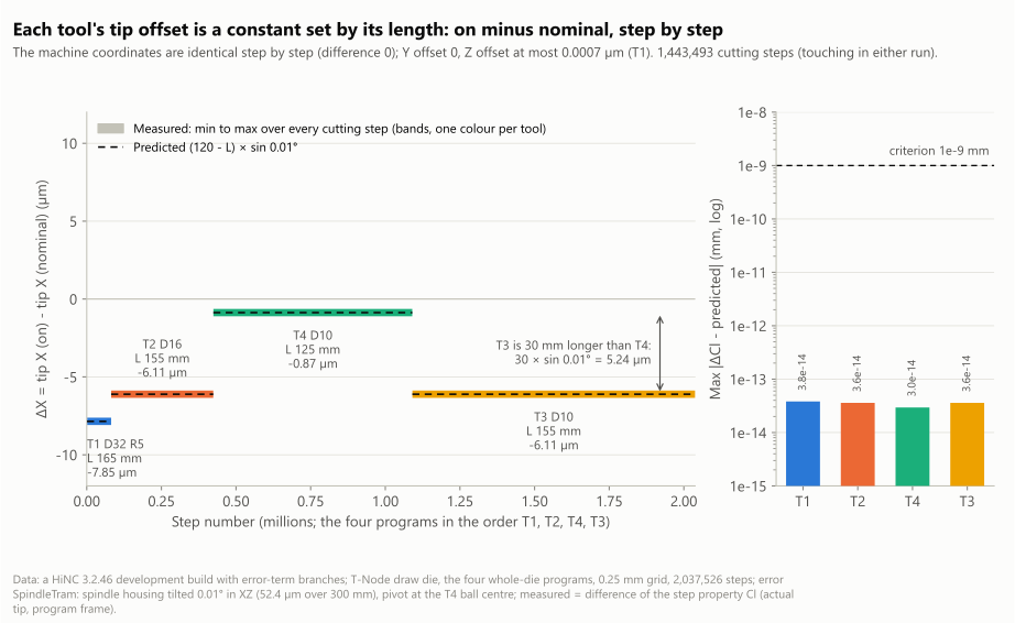
Error terms on, marked: each cutting step's tool-tip X offset (Cl minus the nominal run, program coordinates) against the step number. Each cutter is a flat line (the band spans the cutter's cutting steps from minimum to maximum) on the dashed prediction (120 − L)·sin 0.01°: T1 −7.85, T2 −6.11, T4 −0.87, T3 −6.11 µm; the arrow marks the 5.24 µm by which T3 moves further than T4. Right: each cutter's largest difference from the prediction (log scale, at most 3.82 × 10⁻¹⁴ mm) against the plan's 1 × 10⁻⁹ mm (dashed). Whole die, 0.25 mm; a HiNC 3.2.46 development build with error-term branches.
The part: which way each face moves, and how far
How it was measured:
- Every vertex of the on run's exported cut (2,419,951 vertices) was given its signed distance d to the nominal cut: positive = material left (Diff blue), negative = cut too deep (Diff red). HiNC's Diff gives the pictures and the counts; the numbers of the deviations come from this measurement.
- The distance search looks only at the 12 nearest triangle centroids, so it reads an upper bound of |d|. The vertices it read beyond 8 µm were measured again with the exact point-to-triangle distance to the nominal cut.
- Which face a vertex belongs to goes by the outer normal of the nearest triangle of the design model. The wall parts, the deep-end floor, the binder's east strip and the trimmed case's boxes were set by the design before the play; the faces T4 finishes (cavity, z −18…−0.05), the whole binder face (|z| < 0.05 mm, more than 12 mm outside the drawing opening) and the walls facing ±Y were delimited at the analysis.
| Face | Finished by | Vertices | Measured: median (p10…p90) | Predicted | The plan's range |
|---|---|---|---|---|---|
| Faces T4 finishes (cavity, z −18…−0.05) | T4 | 312,709 | 0.000 (0.000…0.000), largest |d| ≤ 0.077 | 0 | |median| ≤ 1.5 |
| Left outer wall, upper part | T4 | 74,690 | 0.000 (0.000…0.000) | 0 | |median| ≤ 1.5 |
| Left outer wall, lower part (faces +X) | T3 | 73,056 | −5.177 (−5.237…−4.199) | −5.219 | −5.2 ± 1.0 |
| Right closing wall, upper part | T4 | 37,734 | 0.000 (0.000…0.000) | 0 | |median| ≤ 1.5 |
| Right closing wall, lower part (faces −X, 10° draft) | T3 | 57,128 | +5.148 (+3.399…+5.162) | +5.149 | +5.2 ± 1.0 |
| Deep-end floor | T3 | 50,292 | −0.598 (−0.715…−0.057) | −0.628 | — |
| Walls facing ±Y (z −40…−25) | T3 | 21,364 | +0.023 (−0.242…+0.405) | +0.002 | — |
| Binder face, whole | T1 | 796,235 | −1.612 (−1.841…−1.056) | −1.595 (row model) | −1.6 ± 0.5 |
| Binder face, east strip (x 102–150) | T1 | 214,113 | −1.620 (−1.840…−1.123) | −1.644 (−1.92…−0.98) | −1.6 ± 0.5 |
Micrometres. The binder face takes the vertices with |z| < 0.05 mm more than 12 mm outside the drawing opening; the walls facing ±Y take |n_y| > 0.95 and |n_x| < 0.1. The largest |d| on the faces T4 finishes is a search value, an upper bound (not measured exactly).
- Every face lands on its prediction. The nine boxes' medians lie within 0.05 µm of their predictions, and every item of criterion 5 is within its range.
- The box and the wall itself. The left outer wall's lower box also holds vertices that do not lie on the steep wall (p90 −4.20), and its median is −5.18; the wall alone (|n_x| > 0.9, z −30…−23) reads −5.23. The right closing wall reads +5.15 either way.
- Vertex by vertex. For every vertex of the cavity (z < −0.05, 1,204,010 vertices) a model gives “0 where T4 finishes, −30·sin θ·n_x where T3 finishes”, the finishing cutter told by the contact height. Measured minus model: median 0.00, p01 −0.59 and p99 +0.59 µm; 97.48 % within ±0.5 µm and 98.99 % within ±1 µm.
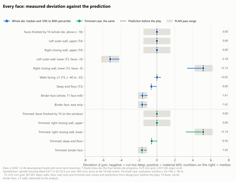
Each face's measured deviation (dot = median, line = p10 to p90; blue = whole die, green = trimmed case) against the prediction made before the play (short black dashed tick) and the plan's pass range (grey box). Faces T4 finishes 0.00, the left outer wall's lower part −5.18, the right closing wall's lower part +5.15, the binder face −1.61, the deep-end floor −0.60, the walls facing ±Y +0.02 µm (whole-die medians). The boxes and predictions of the walls, the deep-end floor, the east strip and the trimmed case come from the design (before the play); the faces T4 finishes, the whole binder face and the walls facing ±Y were delimited at the analysis. Axis symmetric at ±8 µm, negative = cut too deep, positive = material left. 0.25 mm; a HiNC 3.2.46 development build with error-term branches.
The feature boxes (program coordinates, mm)
| Face | Box [x0, y0, z0]–[x1, y1, z1] |
|---|---|
| Left outer wall, upper part | [−91, −110, −18]–[−72, 110, −2] |
| Left outer wall, lower part | [−87, −105, −40]–[−71, 105, −23] |
| Right closing wall, upper part | [55, −60, −19]–[86, 50, −3] |
| Right closing wall, lower part | [70, −55, −51]–[82, 50, −23] |
| Deep-end floor | [20, −35, −58]–[60, 35, −49] |
| Binder face, east strip | [102, −150, −0.2]–[150, 150, 0.05] |
| Trimmed: right closing wall, upper part | [55, −60, −19]–[86, −15, −3] |
| Trimmed: right closing wall, lower part | [70, −55, −51]–[82, −15, −23] |
| Trimmed: deep-end floor | [24, −86, −58]–[60, −15, −49] |
| Trimmed: binder strip | [102, −110, −0.2]–[125, 10, 0.05] |
The seam: too deep on one wall, material left on the other, above the tip split
The vertices of the two walls (design normal |n_x| > 0.9), binned by height every 0.25 mm, median per bin:
| Wall | Vertices | z −30…−23 | z −18…−10 | Step height | Half-step position | Design's position | Contact point from the actual passes |
|---|---|---|---|---|---|---|---|
| Left outer wall (faces +X) | 121,828 | −5.23 µm | 0.00 µm | 5.23 µm (predicted 5.22) | z −19.63 (the bin at −19.75 reads −5.20, at −19.5 0.00) | −20.1 | −19.88 (T3's highest pass, tip at −24.5) |
| Right closing wall (faces −X) | 75,869 | +5.15 µm | 0.00 µm | 5.15 µm (predicted 5.15) | z −21.58 (the bin at −21.75 reads +5.15, at −21.5 +1.26) | −21.1 | −21.37 (T4's lowest pass, tip at −25.5) |
- Which cutter wins the overlap. Both D10s cut the tip band z −25.5 to −24.5. On the left outer wall T3 cuts deeper than T4, so T3 wins up to its highest pass; on the right closing wall T3 leaves material, so T4 wins down to its lowest pass.
- Why above the tip split. A ball meets a steep wall with its side, r(1 − n_z) above its tip: n_z is about 0.076 on the left outer wall and about 0.174 on the right closing wall, with r = 5 mm.
- Not where the design put it. The design assumed T3's highest pass at a tip height of −24.85 and T4's lowest at −25.2; in the per-step record the touching steps' tips run from −56.995 to −24.5 for T3 and from −25.5 to 0 for T4, exactly the two ends of the overlap band. From the actual passes, the contact point lies 0.25 mm (about one cell) from the measured position on the left outer wall and 0.22 mm on the right closing wall. The plan set no criterion on the step's position; this is a finding about the prediction and changes no verdict (dilemma 4).
- Above the step, 0. The faces T4 finishes (cavity, z −18…−0.05, 312,709 vertices) read a median of 0.00 µm, at most 0.077 µm (a search value, an upper bound).
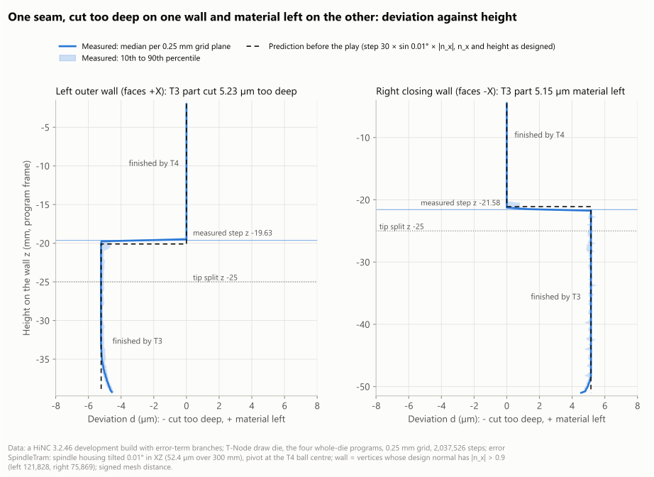
The two walls' deviation against the height on the wall (mesh distance, negative = cut too deep, positive = material left, deviation axis symmetric at ±8 µm). The blue line is each 0.25 mm bin's median and the light blue band p10 to p90; the black dashed line is the prediction made before the play (a step of 30 × sin 0.01° × |n_x| with the design's n_x, 5.22 and 5.15 µm, at the design's z −20.1 and −21.1); the dotted line is the tip split at z −25 and the thin blue line the measured step. The left outer wall is cut 5.23 µm too deep below z −19.63 and the right closing wall keeps 5.15 µm below z −21.58; both read 0 above. Whole die, 0.25 mm; a HiNC 3.2.46 development build with error-term branches.
The binder face: the heel of a tilted face mill
Only T1 face-milled the binder face. The D32 R5's flat bottom tilts with the spindle, its +X side lower than the tip, and each row it mills digs deepest along that row's centre.
- The binder face's 796,235 vertices have a median of −1.61 µm (row model −1.60).
- In 1,381 bins of 0.25 mm along y over 18 rows, the medians reach −1.84 µm at the row centres and −0.89 µm between rows; each row's deepest bin lies at most 0.54 mm from the row centre.
- The trace of the steps. HiNC places the tool at each step and does not sweep between steps. At one step per spindle revolution T1 moves F2100 ÷ S2000 = 1.05 mm from step to step; the tilted heel reaches its lowest only at the steps, and between two steps the face is up to 1.05 mm × sin θ = 0.18 µm shallower. So the model band runs from sin θ·(w − 1.05) to sin θ·w deep (w = √(11² − y′²), y′ the distance from the nearest row centre), widened by ±0.05 µm.
- Of the 1,381 bins, 99.78 % (1,378) lie in the model band. The three outside it are all at the edge of the outermost row, |y| ≈ 172 (−0.03…−0.08 µm). The steps' term was added at the analysis; with the row model written before the play alone (±0.05 µm), 2.03 % (28 bins) lie in it.
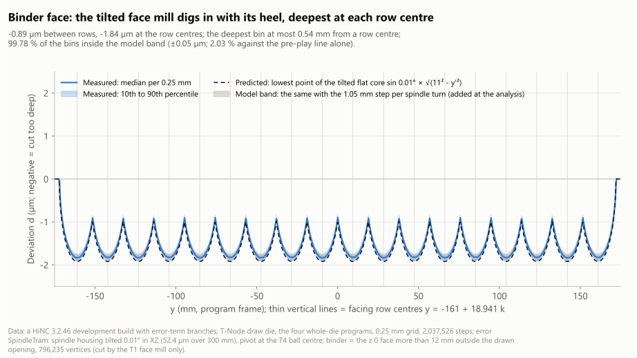
The binder face (z 0, face-milled by T1 alone, more than 12 mm outside the drawing opening): the deviation along y (vertical axis symmetric at ±2.5 µm). The blue line is the median per 0.25 mm and the light blue band p10 to p90; the black dashed line is the tilted flat bottom's prediction sin 0.01° × √(11² − y′²), the grey band the model band that also takes in the 1.05 mm step per spindle turn, added at the analysis, and the thin vertical lines the facing rows' centres. −1.84 µm at each row centre, −0.89 µm between rows; 99.78 % of the bins lie in the model band (2.03 % within ±0.05 µm of the pre-play line alone). Whole die, 0.25 mm; a HiNC 3.2.46 development build with error-term branches.
Every vertex, and the extremes
- All 2,419,951 vertices, the uncut sides of the block included: p01 −5.23, median −0.89 and p99 +5.15 µm; the search reads |d| above 5 µm on 4.27 % of them. The distribution sits within the T3 ball centre's ±5.24 µm.
- The 18 vertices beyond 8 µm are all real. Measured exactly, they read +8.01 to +12.67 µm, the same
as the search values (within 10⁻⁶ µm); none is an artefact of the search. They go beyond what this
error can move a finished face: 5.24 µm for the T3 ball, 4.71 µm for T2, 0 for T4.
- All lie on walls facing −X at z −27.25…−21.25, where T3 finishes: 13 on the wall at the end of the upper wing (x about −3), 4 on the right closing wall (x 75–80) and 1 at (−9.5, −96.2).
- Of the 13 on the wing's end wall, 12 form three short columns along z: five at x −3, y 103.6, z −24.5…−23.5; four at x −3.5, y 108.1, z −22…−21.25; three at x −2.5, y 99.6, z −24.5…−24; neighbours in a column about 0.25 mm apart. The other 6 of the 18 (1 on the wing's end wall, 4 on the right closing wall, 1 at (−9.5, −96.2)) each stand alone, with no other vertex beyond 8 µm within 1 mm. The median of all neighbours within 1 mm of each is +3.95 to +5.20 µm.
- Their cause is not proved (dilemma 7).
- Between 5.3 and 8 µm nothing was measured exactly. The search reads 2,307 vertices below −5.3 µm (2,288 on faces facing +X at x −84.5…−75.25, the left outer wall) and 1,965 above +5.3 µm, of which the 18 beyond 8 µm were measured exactly; the 1,947 between 5.3 and 8 µm (1,942 on faces facing −X) have search values only. The lowest, −6.80 µm, is a search value, an upper bound of |d|.
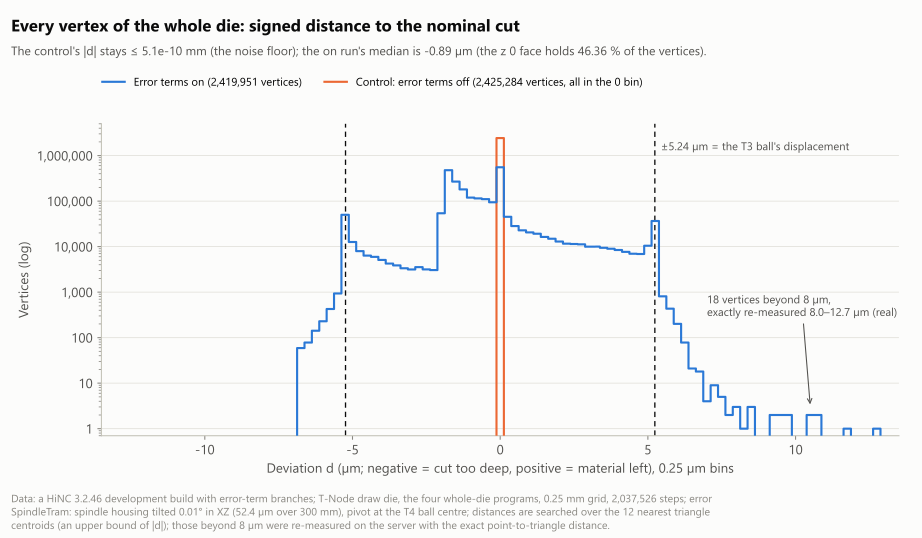
The signed distance of every vertex of the die to the nominal cut (0.25 µm bins, log counts, horizontal axis symmetric at ±13.5 µm). Blue: error terms on (2,419,951 vertices); orange: the control (error terms off, 2,425,284 vertices, all in the 0 bin, largest |d| ≤ 5.1 × 10⁻¹⁰ mm); dashed: the T3 ball's displacement, ±5.24 µm. The 18 vertices beyond 8 µm read 8.0–12.7 µm when measured exactly. 0.25 mm; a HiNC 3.2.46 development build with error-term branches.
Marked and unmarked
This case has no unmarked run. All four programs are plain three-axis Fanuc programs: G54, G43 Hn,
no G43.4, G68, G68.2, M128 or TRAORI, and no CL. The machine coordinates come from the program
and its offsets alone, so whether or not the controller knows that the spindle is tilted, it computes the
same machine coordinates, and the error is cut into the part all the same
(What a mark changes). An unmarked run should
match the on run's tips and cut bit for bit; that is the design's inference, and this case did not play
it to check.
The control run and the Diff on the canvas
The control run (switch off, with a Diff) is the nominal run played again: in both sets its Cl, MC and touching steps equal the nominal run's bit for bit. The whole-die control's exported cut lies at most 5.1 × 10⁻¹⁰ mm from the nominal cut at its 2,425,284 vertices, 100 % within ±0.3 µm; no vertex reaches 10⁻⁶ mm, the threshold above which vertices were measured exactly.
The three pictures below alternate in place at one camera between the run with the error terms on (marked) and the control (off), 0.9 s a frame. Each is the run's recorded stock put back on the canvas with its Diff, not a replay; the canvas carries no interface text, so the English and Chinese captures are the same pixel for pixel, and only the labels differ.
The whole die's Diff from straight above (+X to the right, +Y up; the 320 × 350 mm block with the riser plate grey on either side), alternating in place. With the error terms on, the binder face shows pale yellow-green stripes along X, one every 18.9 mm (the facing rows, about 1.8 µm too deep at their centres and about 0.9 µm between them); a yellow line runs along the foot of the left outer wall (about 5.2 µm too deep); the right closing wall is blue-green (about 5.1 µm of material left). With them off the whole die is green. The two bright glows at the lower left and lower right are reflections of the canvas lights. Diff colour scale ±0.01 mm (red = cut too deep, blue = material left, green = 0, both signs weighted alike); 0.25 mm; a HiNC 3.2.46 development build with error-term branches.
The whole die's Diff from above on the −X side, alternating in place. The right closing wall, which faces −X, faces the camera; the left outer wall, which faces +X, is on the near side with its face out of view. With the error terms on, the right closing wall's lower part is blue-green (about 5.1 µm of material left) and its upper part green, the binder face faintly striped; with them off the whole die is green. Scale, grid and build as above.
The right closing wall of the oblique view above (faces −X, 10° draft), magnified twice, alternating in place. With the error terms on, the wall splits in two near z −21.6 mm: below, the part T3 finished is blue-green (5.15 µm of material left, median); above, the part T4 finished is green (0.00 µm); with them off the whole wall is green. The colour bar and the scale bar are magnified with the picture (the bar still stands for 47.1 mm). Scale, grid and build as above.
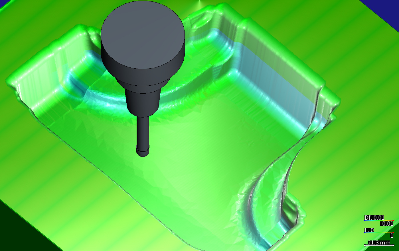
The holder in view, closer: the same parking pose. T3's BT40 shrink-fit holder, its long neck (neck Ø9.4 × 60, 65 mm stick-out) and the D10 ball above the cavity; at the upper right the right closing wall's lower part is blue-green (material left), and the binder face carries faint stripes. T3 is 30 mm longer than T4, which was touched off, and the step is those 30 mm times sin 0.01°. Diff colour scale ±0.01 mm (red = cut too deep, blue = material left, green = 0, both signs weighted alike); 0.25 mm; a HiNC 3.2.46 development build with error-term branches.
Collision detection was on in all six runs and reported no collision.
Diff--Stats of the four runs with a Diff
| Run | Reported leaves | Surface leaves before comparison | Expanded on demand | New nodes | NaN leaves | Measured wires | Unmeasured wires | Target triangles |
|---|---|---|---|---|---|---|---|---|
| t-control | 949,242 | 947,367 | 1,416 | 3,291 | 16 | 3,660,511 | 1,481 | 1,867,014 |
| t-on | 954,287 | 952,475 | 1,232 | 3,044 | 914 | 3,696,145 | 19,179 | 1,867,014 |
| f-on | 2,346,473 | 2,339,687 | 3,151 | 9,937 | 0 | 9,290,157 | 278 | 4,673,494 |
| f-control | 2,354,001 | 2,347,197 | 3,118 | 9,922 | 0 | 9,322,012 | 36 | 4,673,494 |
The nominal runs make no Diff. The target triangles are fewer than the exported meshes': 4,673,494 against 4,673,638 on the whole die and 1,867,014 against 1,867,092 in the trimmed case; this was not pursued. The trimmed on run has more NaN leaves (914) and unmeasured wires (19,179) than the trimmed control (16 and 1,481), while the whole-die runs have no NaN leaf; this was not pursued either.
The trimmed case
The trimmed case played before the whole die, on the evaluation window x 20–100, y −90 to −10. The design set the boxes of the right closing wall's upper and lower parts, the deep-end floor and the binder strip before the play: the first three inside the evaluation window, the binder strip (x 102–125) outside it and inside T1's window. The faces T4 finishes in the window are the vertices at z −18…−0.05 inside the evaluation window, taken at the analysis. Every face agrees with the whole die:
| Face | Vertices | Measured: median (p10…p90) | Predicted |
|---|---|---|---|
| Faces T4 finishes in the window (z −18…−0.05) | 49,025 | 0.000 (0.000…0.000) | 0 |
| Right closing wall, upper part | 15,726 | 0.000 (0.000…0.000) | 0 |
| Right closing wall, lower part | 21,878 | +5.143 (+3.242…+5.162) | +5.149 |
| Deep-end floor | 25,799 | −0.560 (−0.738…+0.019) | −0.600 |
| Binder strip (x 102–125, inside T1's window) | 41,014 | −1.648 (−1.846…−1.150) | −1.655 (−1.92…−1.016) |
Micrometres. Only the boxes in this table are judged: the faces T4 finishes, the right closing wall's two parts and the deep-end floor lie inside the evaluation window, and the binder strip outside it, inside T1's window (the design wrote beforehand that the edges of T1's and T2's windows carry bands of colour, which are not judged; only the boxes are). The extremes of the trimmed case's 969,313 vertices are search values that were not measured exactly, and are not cited; the 8,294 vertices the search reads beyond 10 µm (|d|) all lie outside the evaluation window and were not looked into.
Against the base case's deflection
The base case's whole-die acceptance (dated 2026-11-14, with physics on, a separate play on another HiNC build): T3 bends up to 132 µm with a median of 12.6 µm over its cutting steps, and 7.4 % of its cutting steps bend more than 25 µm; T4 bends up to 20.2 µm. Here physics is off and the results hold no deflection, so the two can be set side by side only as a matter of scale:
- The 0.01° step of 5.24 µm is 41.6 % of T3's median deflection and 3.97 % of its maximum.
- Deflection changes from step to step with the cutting load; a spindle tilt is the same on every step of one cutter, so it leaves a step of one height along the whole seam.
- At a typical acceptance value of 0.003° (scaled by the formula, not played) the step is 1.57 µm and the binder row centres −0.58 µm. On this die, T3's median deflection alone is larger than the 0.01° step.
What the runs cost
All six runs played on private instances of a HiNC 3.2.46 development build with error-term branches on the shared 32-thread server, at 0.25 mm and one step per spindle revolution, with physics off and collision detection on, one run at a time.
| Run | Programs | Steps | Wall clock | Steps per second | Peak memory (VmHWM) |
|---|---|---|---|---|---|
| t-nominal | trimmed | 367,941 | 1,852.5 s | 198.6 | 3.47 GiB (3.73 GB) |
| t-control | trimmed | 367,941 | 935.8 s | 393.2 | 3.83 GiB (4.11 GB) |
| t-on | trimmed | 367,941 | 945.8 s | 389.0 | 4.52 GiB (4.86 GB) |
| f-nominal | whole die | 2,037,526 | 3,443.0 s | 591.8 | 9.68 GiB (10.40 GB) |
| f-on | whole die | 2,037,526 | 3,488.2 s | 584.1 | 13.01 GiB (13.97 GB) |
| f-control | whole die | 2,037,526 | 3,258.1 s | 625.4 | 12.50 GiB (13.42 GB) |
- In all, the six runs took 13,923.4 s, about 3 h 52 min.
- Against the plan. The plan estimated 25–70 minutes per whole-die run and a VmHWM of 10–16 GB without the Diff. Each whole-die run took about 54–58 minutes; the nominal run, with no Diff, peaked at 9.68 GiB (10.40 GB), and the two runs with a Diff 3.33 and 2.82 GiB above it.
- Wall clock runs from the start of the play to the poll that read
Finished, so it includes the Diff and the export after the play; the status was polled every 5 s, so it can be up to 5 s late. Whether other work was playing on the server at the same time is not in the records, so the wall clock may include that load. - Memory is converted from bytes: GB = bytes ÷ 10⁹, GiB = bytes ÷ 2³⁰.
- The pictures replay nothing. The recorded stock goes back on the canvas with its Diff; for the two holder pictures, a parking program that moves only in the air is played on top.
What it means
For a machining engineer.
- A spindle 0.01° out of tram against the Z travel (52 µm per 300 mm), with one cutter touched off, moves each cutter by how much further it reaches than the touched-off one: 30 mm further, and the ball centre moves 30 mm × sin θ further. This die's two D10 finishing cutters differ by exactly 30 mm, so the walls where they meet carry a 5.2 µm step: too deep on the wall facing +X, material left on the wall facing −X.
- The step is not at the tips' split but a few millimetres higher up the wall (here z −19.63 and −21.58), because a ball meets a steep wall with its side.
- A flat-bottomed face mill digs shallow hollows with its heel that follow its rows (here 0.9–1.8 µm, one row every 18.9 mm).
- The size: a typical 0.003° gives only 1.57 µm; on the same die T3's median deflection is 12.6 µm.
- In HiNC, a spindle tilt measured on a machine can go into that machine's model, and where it shows on one's own part, and how much, can be seen before the part is cut.
For a teacher or a student.
- Why a tilt of the whole Z axis leaves no step between cutters while a tilted spindle housing does:
once
G43has taken up the tool length, only a tilt of the tool axis brings the tool length into the offset. - How the tip offset follows from the machine chain, and why the touch-off reference is the deviation's zero.
- A ball's contact height on a steep wall, r(1 − n_z); the heel of a tilted flat bottom, sin θ·√(11² − y′²); and the trace of at most 0.18 µm that one step per spindle turn leaves on a face.
For someone weighing the approach.
- Cost. Six plays, 13,923.4 s of server time, at most 13.01 GiB each.
- Predictions written before the first play: the per-step tip meets the formula within 3.82 × 10⁻¹⁴ mm in each component; the nine faces' medians lie within 0.05 µm of their predictions. The binder's row model needed the 1.05 mm step band, added at the analysis, to hold 99.78 % of the bins (2.03 % with the row model written before the play alone).
- Misses, as measured: the step's position is about 0.5 mm from the design's (the design assumed other passes); 18 vertices go beyond what the error can move a finished face, their cause not proved; criterion 2 failed as written on the trimmed case.
Honest limits
- One error only, a constant one, in one plane. The spindle tilt lies in the XZ plane alone; a real spindle may be out of tram in XZ and YZ both. An error term holds only a constant error (a squareness, an axis tilt, a rotary axis' location, a spindle tilt, a machine-zero offset); positioning errors, straightness, backlash, servo mismatch and thermal deformation cannot be put in (Machine Geometric Error).
- The value is chosen, not measured. 0.01° stands for “a spindle head due for re-tramming”; “a typical acceptance value of about 0.003°” comes from the design, which could not read ISO 10791-2's tolerance table and calls it only “typical”.
- The touch-off is modelled by where the pivot sits. The case takes X and Y to be touched off with T4; another cutter, or another way of touching off, moves the deviations' zero (the step's height stays the same). HiNC's P0 does not take up the offset as a real touch-off does.
- The tool lengths are the tool library's. A real presetter measuring a tilted flat-bottomed cutter reads its lowest edge, so H1 would come out 11·sin θ longer, and the binder face would then carry stripes of material left, 0 to +5.4·sin θ, rather than cut too deep (the design's inference, not played).
- Geometry only. Physics was off, so the results hold no deflection. On a real machine the step at the T4/T3 seam also carries the difference between the two cutters' deflections and the errors of their measured lengths; the comparison with the base case's deflection mixes two plays (that one with physics on and on another HiNC build) and gives only the scale.
- Plain three-axis programs, so no unmarked run. How much a controller that knows the error could take back cannot be shown with this case.
- “Every line run” is indirect evidence:
Finished, a step on every program's last motion line, and the motion lines without a step of their own all of zero length or shorter than one spindle revolution. The records do not keepnc'sSys-Init--FileLines. - The programs played are copies. The error-term project's Save As copied the
NC/folder with it; the analysis took its line numbers from the base case'sNC/*.nc, and the two were not compared byte for byte. Nothing outside the error-term folder changed. - The vertices are classified by the design's normals. Which wall, whether |n_x| > 0.9 and which cutter the per-vertex model uses all go by the nearest triangle of the design model, not by the cut face's own normal, so a corner can be classed wrong. This touches the wall profiles and the per-vertex model, not the box medians of criterion 5.
- The mesh distance's extremes were checked only in part. The 18 beyond 8 µm were measured exactly, their cause not proved; between 5.3 and 8 µm the values are search values; the trimmed case's extremes were not measured exactly.
- The holder pictures show a parking pose. The parking program stops T3 in the air at (X −60, Y 0, Z 10), not in a cutting pose.
- Observations not pursued.
- The trimmed nominal run took 1,852.5 s, twice the trimmed control (935.8 s) and on run (945.8 s) with the same number of steps; the records do not say why.
- The trimmed on run's 914 NaN leaves and 19,179 unmeasured wires against the trimmed control's 16 and 1,481; the whole-die runs have no NaN leaf.
- The target triangles of
Diff--Statsare fewer than the exported meshes' (4,673,494 against 4,673,638 on the whole die, 1,867,014 against 1,867,092 trimmed).
What a reader can take to their own case
- Put a spindle tilt just before the spindle branch, not before Z. Before Z,
G43cancels the tool lengths and every cutter moves alike; before the spindle, each cutter moves by its own length (Where an Error Term Goes). - Put a static error's pivot at the touch-off reference. For a ball touched off against a side, that is its centre, since it touches with its equator. The deviation is then 0 at the touch-off, and the nominal work offset is the one a real touch-off would find (Work offsets on a machine with error terms).
- Look where cutters of different lengths hand over. A spindle tilt leaves a step there of (difference in length)·sin θ·|n_x|, of opposite sign on walls that face opposite ways.
- Expect the step above the tip split on a steep wall, by r(1 − n_z), and read the actual pass heights from the per-step record rather than from the CAM's intent.
- A tilted flat bottom digs in with its heel, R_core·sin θ at the row centres; at one step per spindle turn the face is up to (feed per turn)·sin θ shallower between steps. Model that before judging a sub-micrometre face.
- Write the prediction and the criteria before the first play, and judge each criterion on its whole text: a criterion that fails as written is reported as failed, with its cause and scope.
- Check the tool tip first, against the formula. The per-step tip checks the model within 3.82 × 10⁻¹⁴ mm here, before any mesh is read.
- Take the cutting steps as the union of both runs' touching steps when the error changes which steps touch.
- Make the nominal cut the ideal geometry, so that the Diff shows the error rather than the toolpath's own marks.
- Measure a mesh distance's extremes exactly before citing them, and report the real ones whose cause is unknown as exactly that.
- On a plain three-axis program a mark changes nothing in the cut: every error in the chain is cut into the part. A run with the mark cleared differs only under RTCP, a tilted plane or CL playback (What a mark changes).
- Choose a camera that sees the wall you mean. From the side, a cavity shows only the block's outside.
Source and licence
The part comes from the NUMISHEET 2025 industrial benchmark, through the base case:
- Source: Ott, Michael; Martinitz, Katja; Böhm, Viktor; Spörer, Thomas; Hartmann, Christoph; Volk,
Wolfram (Technical University of Munich, Chair of Metal Forming and Casting (utg)), NUMISHEET 2025 -
Industrial Benchmark, Zenodo, version 1, published 2025-11-20,
doi:10.5281/zenodo.17662411. The author field of the
record's Introduction PDF reads “Holzer, K.” where Zenodo lists Katja Martinitz. Search terms if the link moves:
NUMISHEET 2025 Industrial Benchmark,zenodo 17662411,T-Node B-pillar. - What was used: the top surface of the benchmark's target part (an STL), the only geometry the benchmark gives for the drawn part.
- Licence: CC BY 4.0, as the Zenodo record states. The licence gives the material as is, without warranty. The benchmark's file names carry the Mercedes-Benz trade mark; CC BY grants no trade-mark rights, so this page calls the part “NUMISHEET 2025 T-Node” and implies no endorsement by Mercedes-Benz or TUM.
- Attribution, as the base case gives it: “Target geometry: NUMISHEET 2025 Industrial Benchmark, M. Ott, K. Martinitz, V. Böhm, T. Spörer, C. Hartmann, W. Volk (TUM utg), Zenodo doi:10.5281/zenodo.17662411, CC BY 4.0. Draw-die design and machining set-up by Tech Coordinate's agent.”
- What the base case changed: nothing in the source files. The die face and the binder face are derived from the target surface by the agent's scripts, one feasible die rather than the production tool; the block, the tools and holders, the four programs and the machine set-up are the agent's.
What this page adds. One marked error-term branch on the machine, SpindleTram: a spindle tilt of
0.01° directly upstream of the spindle branch. Its place, its value and its pivot are the agent's
choices; the die face, the four programs and the base case's set-up are as they were. No file or figure
of the benchmark is reproduced here. The pictures are HiNC captures, and the charts are drawn from HiNC's
per-step results and cut meshes. Everything is simulated; nothing was cut. The benchmark's organisers
took no part in this case and do not endorse it. This site offers no download; fetch the benchmark from
its Zenodo record.
See Also
- Building Virtual Machine Tools: Error terms — where an error term may go (a spindle housing's tilt between Z and the spindle branch on a three-axis machine), what a mark changes, the Enable Error Terms switch, and work offsets on a machine with error terms
- Kinematic Topology: Error-Term Branches — the nominal chain the controller solves, and which errors it can see
- Machining Issues Outside the Model: Machine Geometric Error — the machine errors the model leaves out
- Geometry Validation — the geometry difference, its detection radius and its colour scale
- Program Zero Alignment — P0, and typing in a measured work offset
- Plunge against Layer Roughing of a Deep Slot on a Z Axis 0.003° Out of Square — an error just before Z instead, the kind dilemma 1 turned down here: one cutter, and the walls leaning with depth
- Showcase — the other cases, and how a case page reads