Forged aluminium wheel, 17 inches: designed from three public numbers (3+2 / 5-axis)
- Original sources
- Numbers only, no model: ANKUSI Open Wheel Fitment Dataset: bolt pattern, centre bore and OE wheel specifications for 7,603 vehicle variants, ANKUSI Wheels engineering team, figshare, version 4, 2026 (doi:10.6084/m9.figshare.33921994); the height of a J rim flange, 17.3 mm, from the German Wikipedia article Autofelge.
- Search keywords
ANKUSI Open Wheel Fitment Dataset,figshare 33921994,Autofelge Form J- Licence
- The data set is under CC BY 4.0; only three of its numbers are used. The wheel is the agent's own design; no wheel maker's model or drawing is used, and the case names no vehicle.
- Attribution
- Wheel size numbers from the ANKUSI Open Wheel Fitment Dataset (ANKUSI Wheels engineering team, figshare, doi:10.6084/m9.figshare.33921994, CC BY 4.0). Wheel design by Tech Coordinate's agent.
- About the case
- A one-piece forged 6061-T6 wheel of a common size: 17 × 6.5J at offset 40, five bolts on a 114.3 mm circle, a 60.1 mm centre bore. It is a machining demonstration of a wheel of this size, not any maker's wheel.
The story
No licence-clean model of a real car wheel could be found; what is public are fitment numbers. An AI agent took three of them and one flange height, designed a five-spoke wheel of its own, and wrote both set-ups as five-axis cutter locations with its own CAM script: the windows roughed and their drafted walls flanked from the face, the stud holes drilled and seated, then the wheel turned over for the back pockets and the valve hole. Through HiNC's web API, HiNC solved the axes of a table-C / swivel-head-B machine, checked every move for collisions, computed the cutting load, wrote the Fanuc program and replayed it. The agent wrote its pass criteria down before the first play and ran a 72° sector of the wheel before the whole.
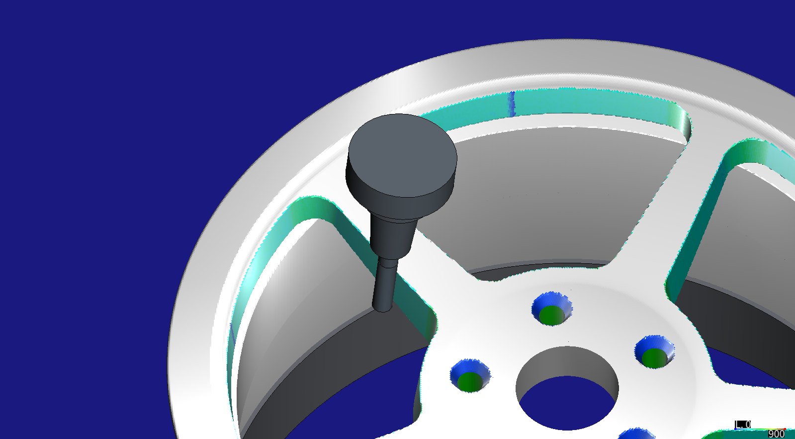
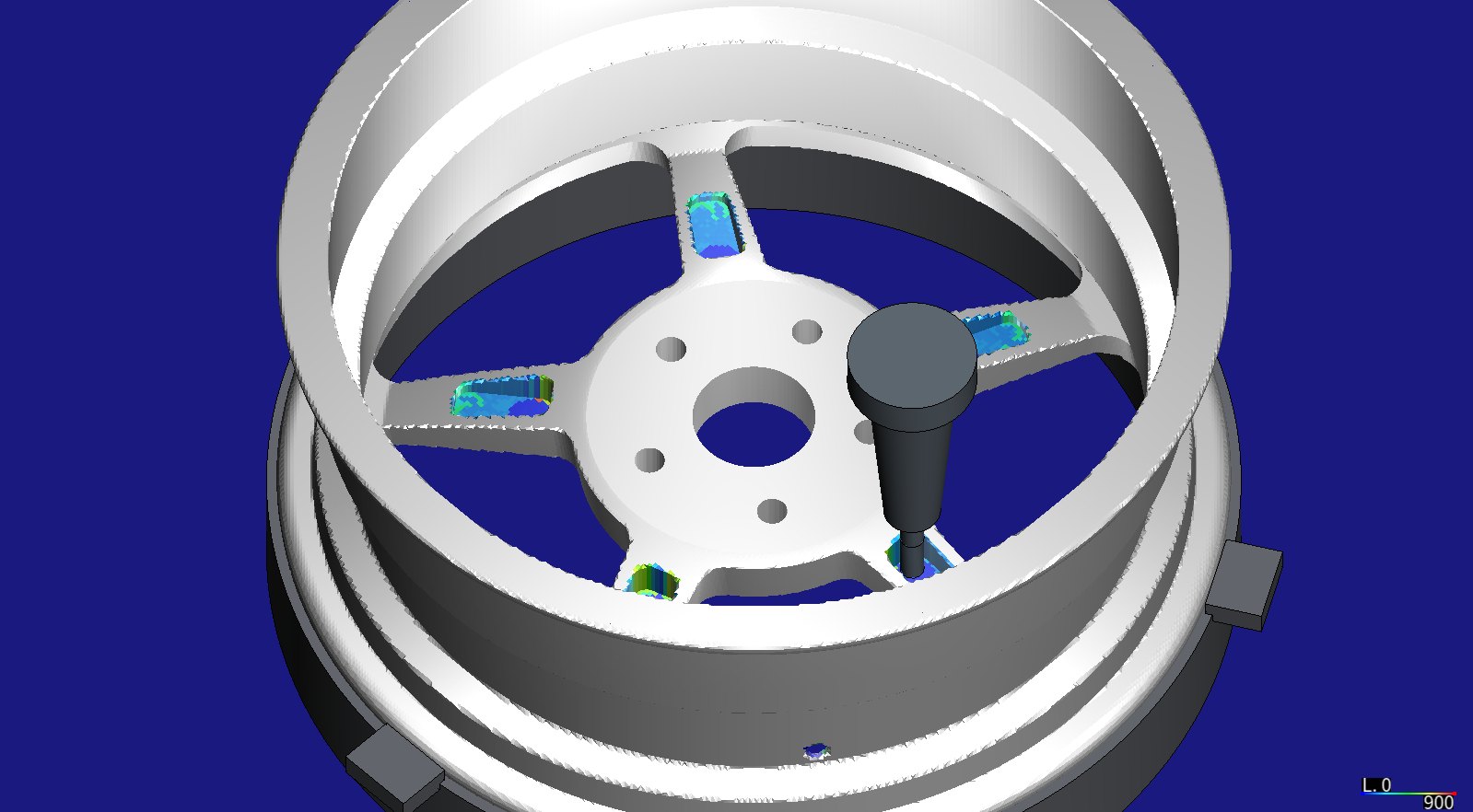
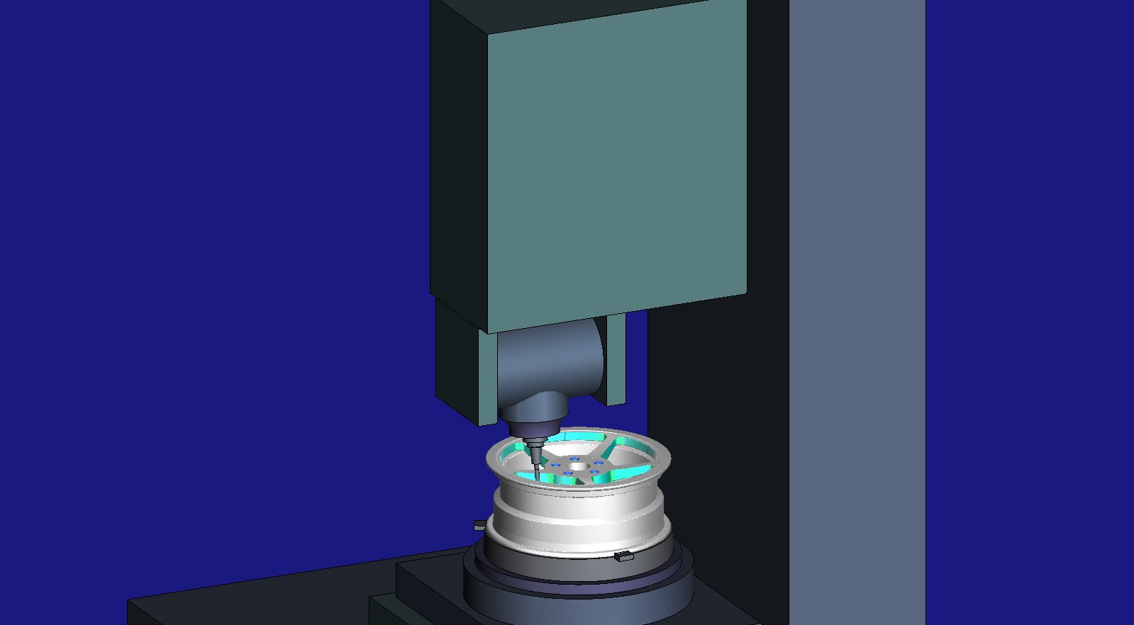
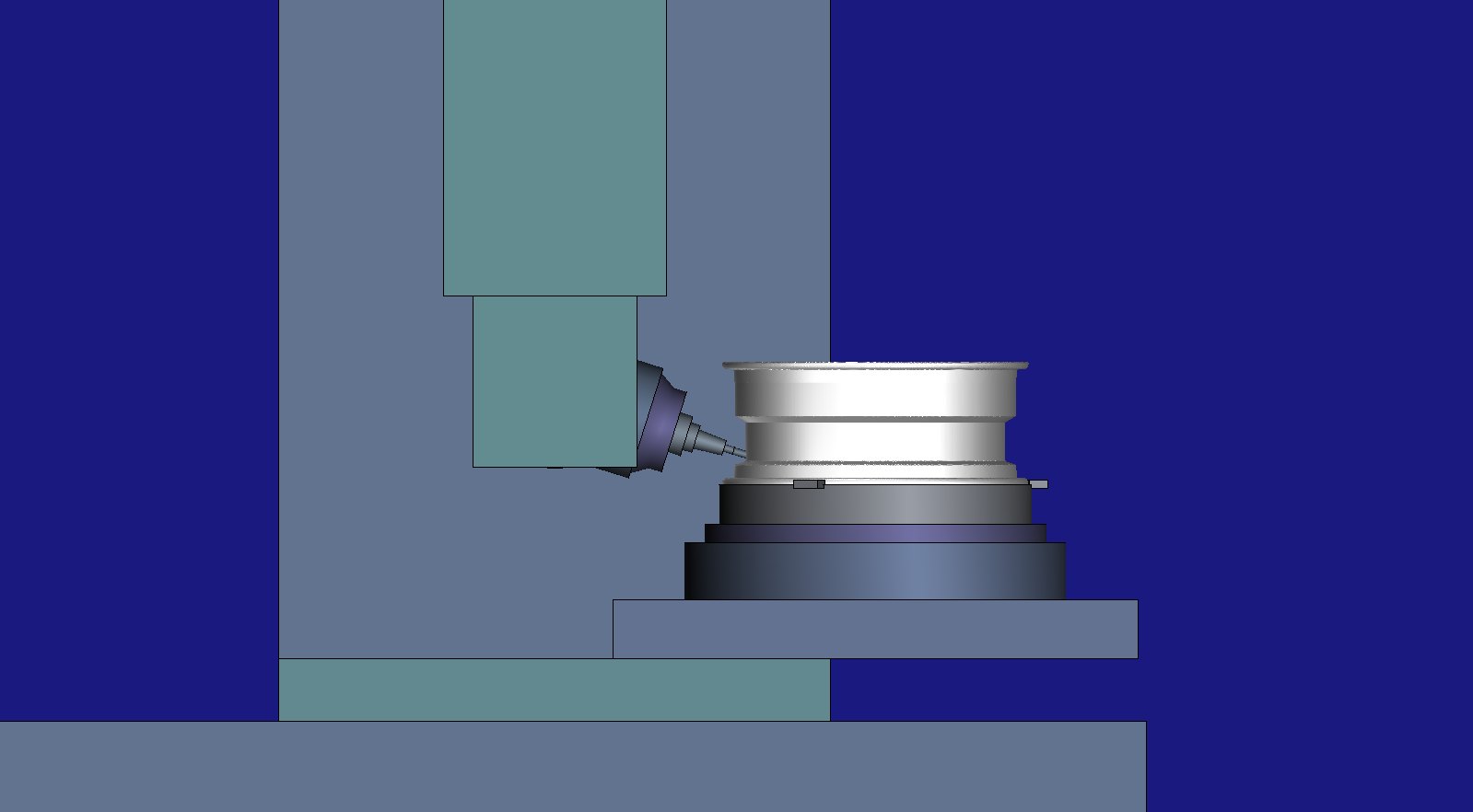
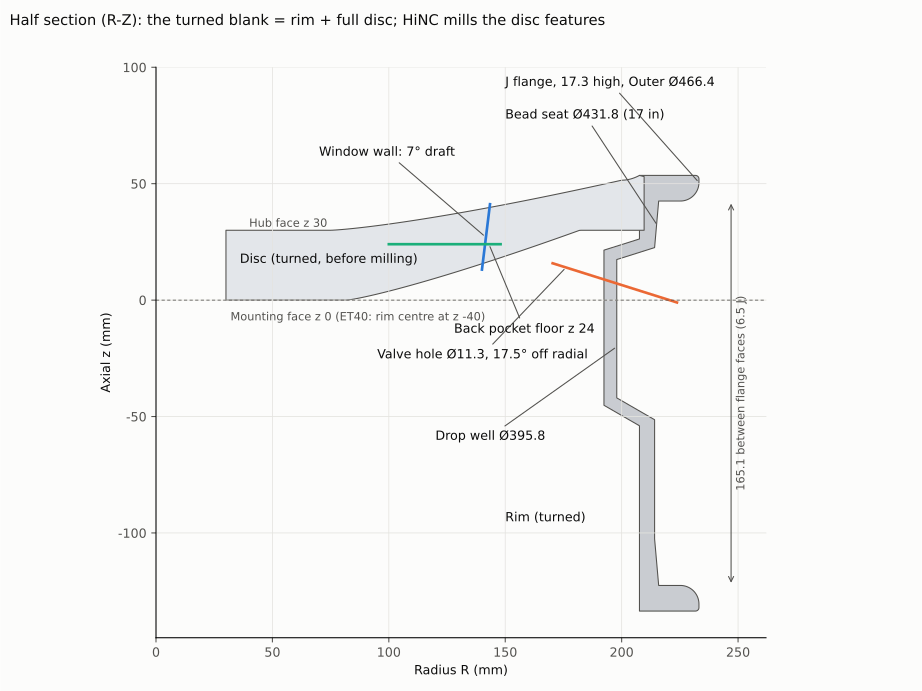
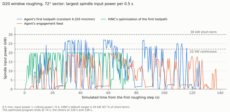
Pictures rendered by HiNC from the wheel Tech Coordinate's agent designed; not a wheel maker's design file. The half section is drawn by the agent's design script, the power chart from HiNC's per-step results.
Four of its fourteen dilemmas
A clean run past the spindle's rating
On the 72° sector HiNC reported no problem, but its per-step results put the 20 mm roughing tool at 1.3 times the spindle's continuous rating, on 997 steps. Each step carries its program line: the peaks sat where the agent's own toolpath cut the full width of the tool, on a link through uncut stock and in narrow necks. The agent re-linked the levels and slowed only the wide cuts; the spindle then stayed within 94 % of its continuous rating for 8 % more time.
One draft all round the window
Windows that run out into the barrel would need a draft that changes along the wall, a twisted surface a cylindrical cutter cannot follow exactly. The agent closed the windows and gave them one 7° draft with R12 corners, so every piece of wall is a plane or a cone: the straight sides are cut 3+2, the corners and arcs in simultaneous five-axis, with the tool touching along a whole line.
A valve hole drilled from the tire side
From the face, the drill would meet the drop well at 72° with the spindle head almost flat over the hub. The hole was turned 17.5° towards the face and drilled in the second set-up from outside the wheel, with the head swivelled to 72.5°; the agent's script placed the head around that pose and found 67 mm to the wheel, and HiNC reported no collision.
Optimize the first toolpath or the fixed one?
Asked to try HiNC's feed optimization, the agent ran it on both of its roughing toolpaths for the sector: the constant feed that overran the spindle and its own fix. HiNC solves each step's feed afresh, and both came out alike: 74 s against 126 s and 138 s, held level at HiNC's power target with no step over the continuous rating.
The other ten, among them a pocket whose holder would have hit the barrel, a rapid retract flagged as cutting, a deliberate collision that proved the holder is checked, and a comparison script tested against the design itself before it judged HiNC's part, are in the full record.
The result
Both set-ups played every line at 0.25 mm with no warning and no collision, as cutter locations and again as the Fanuc programs HiNC wrote from them, which cut the same. The milled faces lie within −0.178 to +0.031 mm of the design. The spindle peaked at 0.67 of its short-term and 0.91 of its continuous rating, the tools at 0.37 of their yield stress, and the nearest holder stayed 15 mm from the wheel. The wheel takes 17 min 34 s of cutting against a target of 20 min. One criterion missed by a hair: one point per set-up, on an edge no tool touches, read 0.302 and 0.319 mm below the turned face against the 0.3 mm allowed, and the full record says so. HiNC's feed optimization then brought the wheel's machining time from 17 min 25 s to 9 min 36 s, 45 % less, with the spindle within its rating at every step; most of the gain sat at the feed limits the agent had set for each tool, and the finishing tool, sped up with the rest, cut with more force and bent further. Everything is simulated; no wheel was cut.
| Key number | What it is |
|---|---|
| 17 min 34 s | simulated machining of both set-ups, 13 min 17 s face up and 4 min 17 s turned over, without tool changes or loading |
| −0.178 to +0.031 mm | the milled faces against the design; all 54,158 sampled points within ±0.3 mm |
| 0 | collisions in the four plays; a holder driven into the wheel on purpose gave 658 steps |
| 0.669 / 0.912 | the 20 mm roughing tool's peak against the spindle's short-term / continuous rating (the first toolpath, on the 72° sector: 0.957 / 1.305) |
| 0.368 | the highest tool stress against yield of the six tools: the valve drill, cutting through the drop well at a slant |
| no difference | the Fanuc programs HiNC wrote, replayed: the same peaks of cutting depth, force, power and stress as the toolpath in all six programs, digit for digit |
| 9 min 36 s | the wheel after HiNC's feed optimization, from 17 min 25 s (−45 %); the spindle at most 0.925 of its continuous rating |
NC optimization of this case →
What it brought
- For a machining engineer: before any aluminium is cut, HiNC shows that a two-set-up five-axis program for a wheel clears its holders and head, which moves of a roughing that looked clean run the spindle past its continuous rating, and that HiNC's feed optimization can take 45 % off the machining time within the spindle's rating, as far as the feed limits set for each tool allow; a finishing pass is better left out of it.
- For a teacher or a student: why one draft lets a cylindrical cutter finish a window exactly; 3+2 and simultaneous five-axis on the same wall; how a valve hole is drilled from the tire side; where contour-parallel roughing hides full-width cuts; what a spindle's short-term and continuous ratings mean.
- For someone deciding whether to use an agent with HiNC: from three public numbers to a wheel of its own design, two five-axis set-ups, an accepted simulation and an optimized program; the pass criteria were fixed before the first run, the toolpath was revised once on HiNC's results, and no second agent rebuilt the case.
Read the full case record: forged wheel
The source and its backup
| Case | Original files | Backup |
|---|---|---|
| Forged aluminium wheel, 17 inches | the fitment data set (figshare) | Showcase-Wheel17-Forged6061.zip |
Only three numbers come from the data set, so there is no original file to
keep. The zip holds the case's SOURCE.md and, under Setup/, the agent's scripts
that design the wheel, write the toolpaths, build the machine and compare the machined part with the
design, the numbers files with every value marked read, derived or chosen, the toolpaths themselves,
the pass criteria and the accepted results; the scripts rebuild the meshes.