Forged aluminium wheel, 17 inches: HiNC's feed optimization takes 45 % off, with the finishing kept as programmed (3+2 / 5-axis)
- Original sources
- Numbers only, no model: ANKUSI Open Wheel Fitment Dataset: bolt pattern, centre bore and OE wheel specifications for 7,603 vehicle variants, ANKUSI Wheels engineering team, figshare, version 4, 2026 (doi:10.6084/m9.figshare.33921994); the height of a J rim flange, 17.3 mm, from the German Wikipedia article Autofelge.
- Search keywords
ANKUSI Open Wheel Fitment Dataset,figshare 33921994,Autofelge Form J- Licence
- The data set is under CC BY 4.0; only three of its numbers are used. The wheel, its toolpaths and the programs optimized here are the agent's own; no wheel maker's model or drawing is used, and the case names no vehicle.
- Attribution
- Wheel size numbers from the ANKUSI Open Wheel Fitment Dataset (ANKUSI Wheels engineering team, figshare, doi:10.6084/m9.figshare.33921994, CC BY 4.0). Wheel design by Tech Coordinate's agent.
- About the case
- The accepted programs of the 17-inch forged aluminium wheel: six five-axis Fanuc programs in two set-ups, 17 min 25 s of machining, every move within the spindle's rating. Here HiNC's feed optimization speeds them up.
The story
The wheel's two set-ups had already passed their acceptance: the window roughing, the five-axis flank of the drafted walls, the stud holes and seats face up, then the back pockets and the valve hole turned over. An AI agent handed the six programs to HiNC's feed optimization and asked what an engineer asks first: how much time it saves, what it does to the finishing passes, and whether any line comes out slower than programmed. It wrote its pass criteria and every setting down before the first run, tried the whole chain on a 72° sector of the wheel, and then optimized and replayed the whole wheel three ways: every pass optimized; the finishing passes kept at their programmed feed; and, on top of that, no step allowed to run slower than programmed.
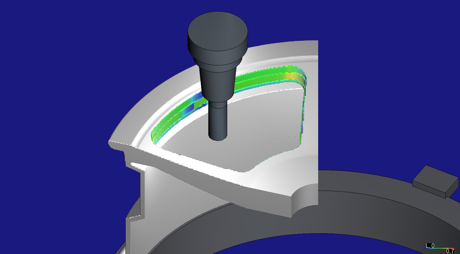
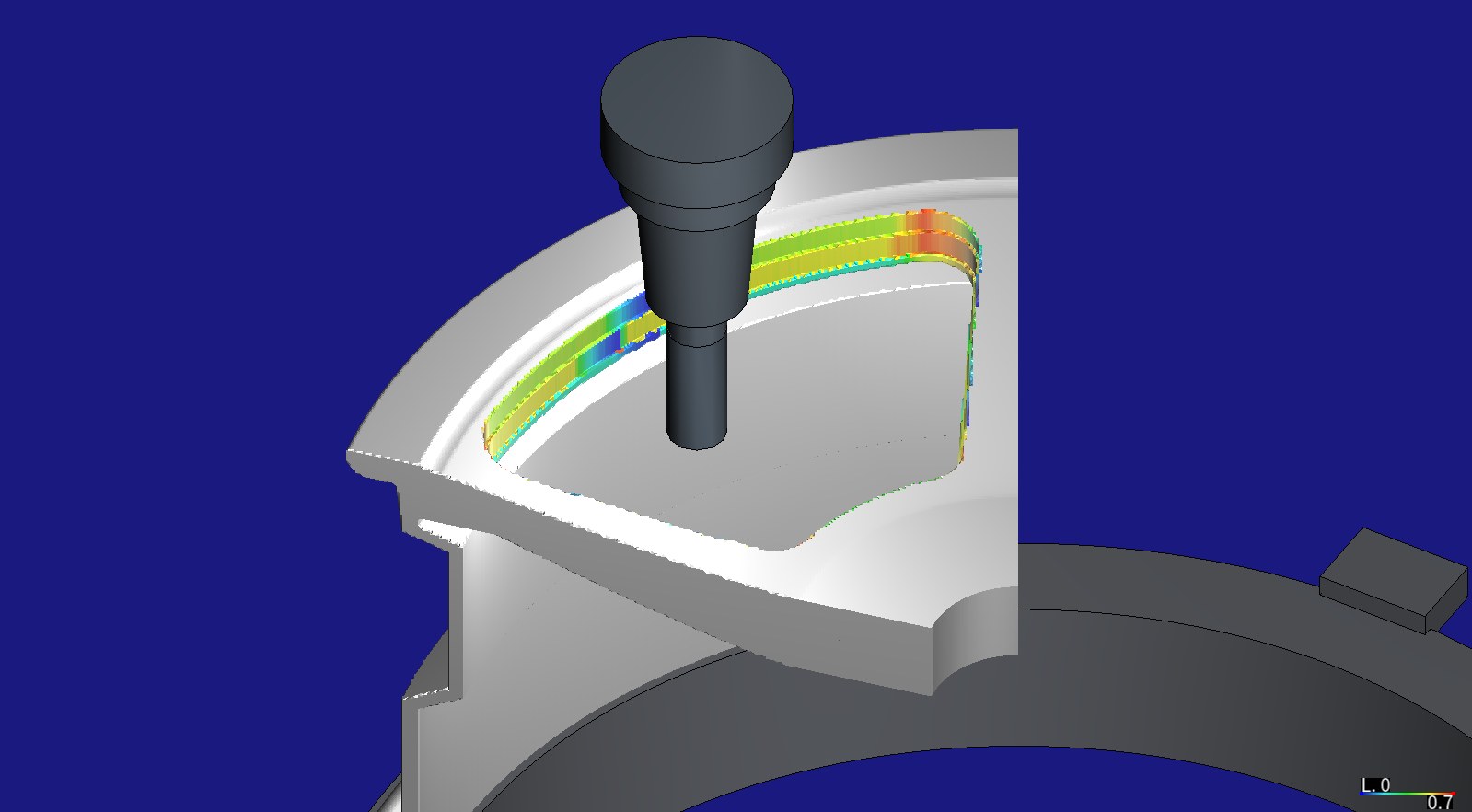
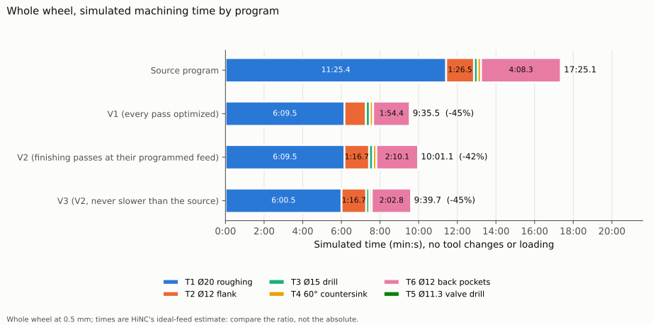
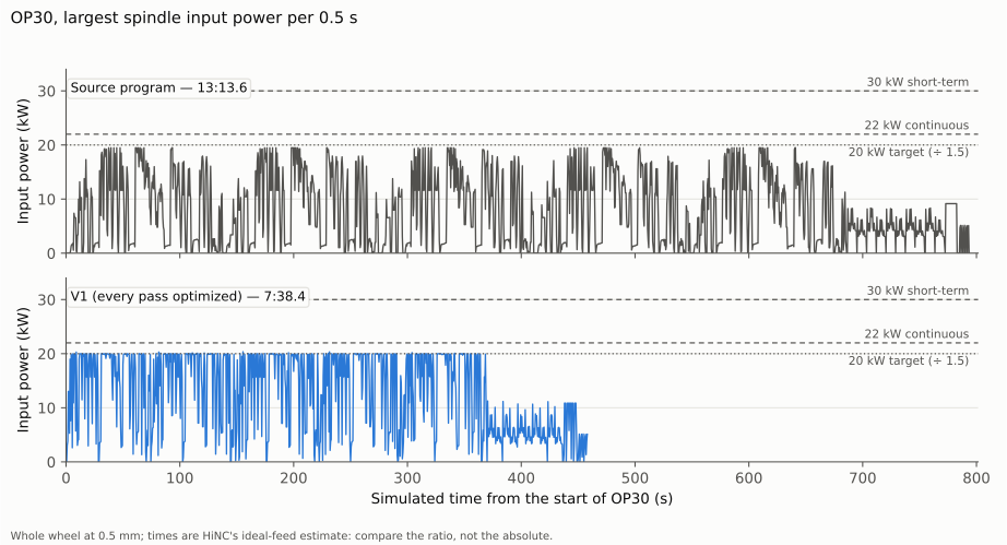
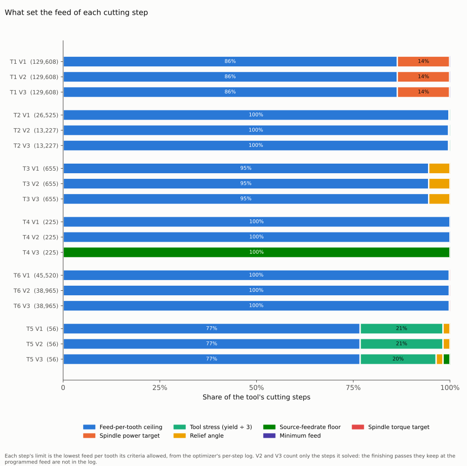
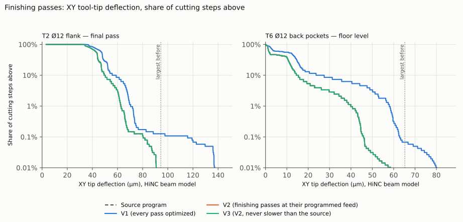
Pictures rendered by HiNC from the wheel Tech Coordinate's agent designed; not a wheel maker's design file. The charts are drawn from HiNC's per-step results; the times are HiNC's ideal-feed estimates, so compare the ratios rather than the absolute times.
| Key number | What it is |
|---|---|
| 9 min 36 s | every pass optimized, from 17 min 25 s (−44.9 %); the spindle at most 0.925 of its continuous rating |
| 10 min 01 s | the finishing passes kept at their programmed feed (−42.5 %); they replay step for step as programmed, and keeping them costs 26 s |
| 9 min 40 s | finishing kept and no line slower than programmed (−44.5 %): 99 % of the time saved |
| 94 → 140 µm | the flank tool's largest bend on its finishing pass when every pass is optimized; unchanged when the finishing is kept |
| 86 % | of the roughing tool's cutting steps run at the feed-per-tooth ceiling the agent chose; the spindle's power set the other 14 % |
| 99.98 % / 100 % | of the milled faces within ±0.3 mm of the design in every version, face up / turned over, as before the optimization |
| 41 min | of server time for the twelve whole-wheel plays, at most 24 GiB of memory |
Four of its eight dilemmas
A force target that did not hold
The plan held the finishing passes with a target force written into the program. On a trial sector the agent checked whether it really capped them: on the five-axis flank, every step already above the target was still allowed the full feed ceiling. So the finishing passes are kept at their programmed feed instead, and the replay shows them step for step as programmed.
A grid coarser than the finishing allowance
The optimization runs on a 0.5 mm grid, and the finishing leaves 0.3 to 0.4 mm. Had the grid read a real cut as air, the optimizer would send the tool into the stock at 20,000 mm/min. On the sector the agent compared both grids and replayed the optimized program on the finer one: no step at the air feed touched the stock.
Most of the pocket tool's time was ramping
136.5 of the back-pocket tool's 188.9 s of cutting were its helical ramps at half its feed per tooth, and the optimizer took them to the ceiling. Chips have the hardest way out of a closed pocket, which the model does not see, so the page says so: a shop would give the ramps a ceiling of their own.
Never slower, and faster still
The agent predicted that forbidding any line to run slower than programmed would win at most 10 s more. It won 21.5 s: it removed the drill's slow-down at its entry and stopped the smoothing from dragging feed changes below the programmed feed. The prediction stays recorded as missed.
The other four, among them a cap rule that would have held a single step, a criterion that counted steps where it meant removed material, and before-and-after pictures from one camera, are in the full record.
The result
All twelve plays ran to the end, and the six replays of the optimized programs had no collision, no rapid move through stock and no warning. Every version kept the shape: 99.98 % of the milled faces within ±0.3 mm of the design face up and 100 % turned over, as before the optimization. Optimizing every pass took the wheel from 17 min 25 s to 9 min 36 s, with the spindle inside its rating at every step, but the finishing tool then bent up to 140 µm instead of 94 µm. Keeping the finishing passes at their programmed feed cost 26 s of the saving and left them exactly as programmed; adding a floor at the programmed feed made no line slower and brought the wheel to 9 min 40 s, 44.5 % less. Most of the gain sits at the feed-per-tooth ceilings the agent chose for each tool, typical values for aluminium rather than a tool maker's data. Everything is simulated; no wheel was cut.
What it brought
- For a machining engineer: on a program already inside the spindle's rating, HiNC's optimization takes 45 % off; with the finishing passes kept and no line allowed slower, 44.5 % remains, which makes the result one to send to a machine. The ceilings given to each tool decide most of it, and the optimizer's per-step log shows which limit set every step.
- For a teacher or a student: what the optimization held here (spindle power, torque, tool stress, the ceiling) and what it did not (force, with no force target set; deflection, which it has no criterion for; the wall it leaves); why finishing passes are protected; why a step is one spindle revolution, so a faster program has fewer of them.
- For someone deciding whether to use an agent with HiNC: from accepted programs to three optimized versions in twelve whole-wheel plays and 41 minutes of server time; the criteria were fixed first, the protection of the finishing was changed on a trial's evidence before the version ran, and the missed predictions are written down.
Read the full case record: the wheel's NC optimization
How the wheel, its toolpaths and these programs were made: Forged aluminium wheel, 17 inches.