SpaceTeamSat1 CubeSat structure: six Al 7075 plates in twenty-four clampings (3-axis)
- Original source
- Tim Munhowen (TU Wien Space Team), SpaceTeamSat1 Mechanical Design, Zenodo, version 1.0, 2025, doi:10.5281/zenodo.15482346.
- Search keywords
SpaceTeamSat1 Mechanical Design,zenodo 15482346,CS_Xminus.STEP- Licence
- CC BY 4.0, given as is, without warranty. The plates are the team's models, unchanged; the stock, the operations and clampings, the fixtures, the tools and holders, the programs and the machine are the agent's. The pictures below are rendered by HiNC, or by the agent from the team's models, or drawn by its scripts from HiNC's readings; the drawings are not reproduced.
- Attribution
- SpaceTeamSat1 mechanical design by Tim Munhowen, TU Wien Space Team (Zenodo, doi:10.5281/zenodo.15482346), CC BY 4.0. Machining set-up by Tech Coordinate's agent.
- About the case
- SpaceTeamSat1 is the 1U CubeSat of the TU Wien Space Team, a student team in Vienna. Its structure is a frame of six Al 7075 plates about 100 mm on a side: two square frames and four side panels with rails, 1.6–1.8 mm sheets and D4 H7 locating bores. The team published the STEP models and a 13-sheet drawing set. The drawings give the material, the general tolerance ISO 2768-f, the surfaces and the H7 holes; they give no fixture, no order of operations and no tools.
The story
An AI agent wrote its own 2.5-axis CAM over the STEP files, with no commercial CAM to start from. Grouping the holes by their axes, it counted 24 clampings: every plate held in a vise by an 8 mm slab left under it, then turned over onto a sub-plate and screwed down through the M3 holes that the drawing says serve the manufacturing; each side panel then stands in the vise three more times for the holes in its two end faces and one edge. Under the side panels' 1.6 and 1.8 mm sheets the sub-plate carries nests shaped to them. The agent took a generic three-axis machine with a 7.5 kW, 24,000 rpm spindle, put every cutter in a shrink-fit chuck at a stick-out sized from a height map of the part grown by the holder's radius, and wrote 24 Fanuc programs. It wrote its pass criteria down before the first play, built the 24 HiNC projects through the web API, each clamping starting from the workpiece the one before left, played all of them at 1 mm, and then accepted the batch at a 0.125 mm cell.
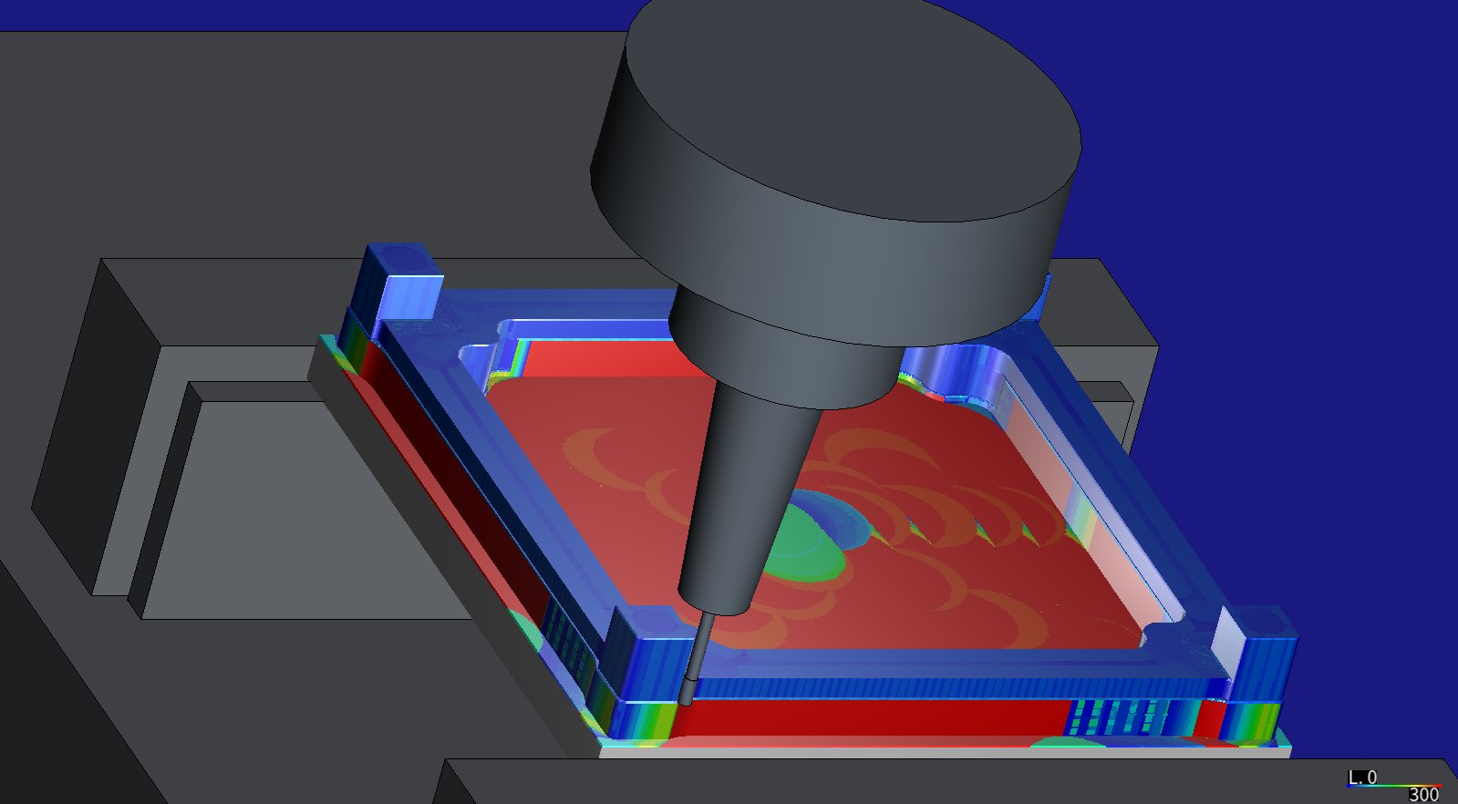
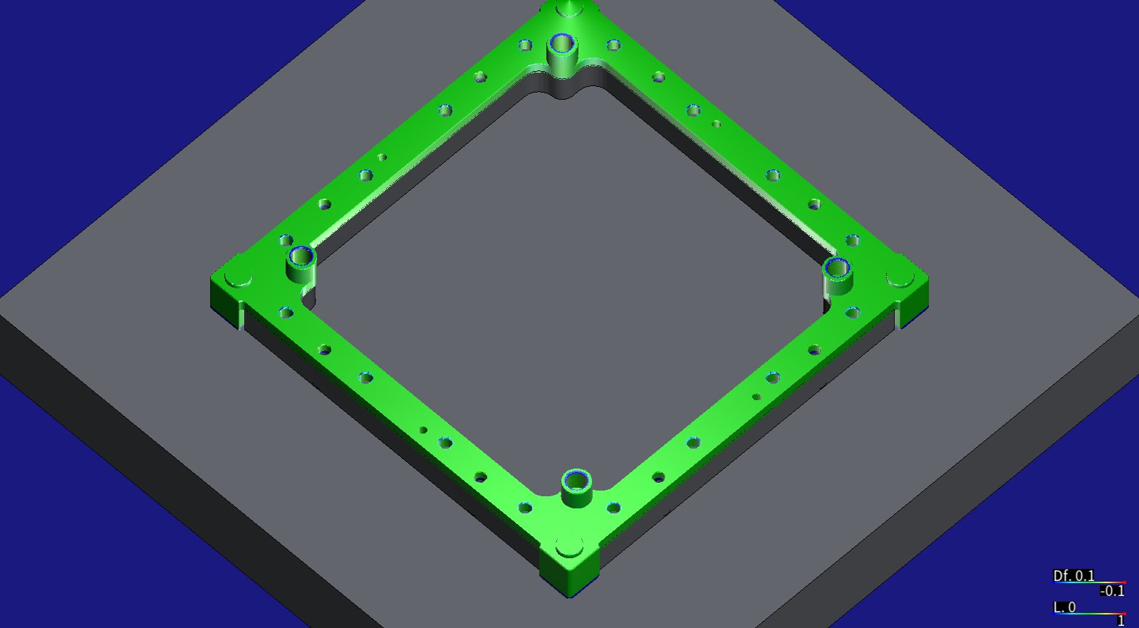
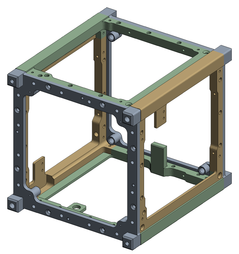
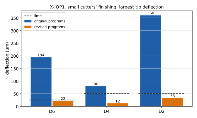
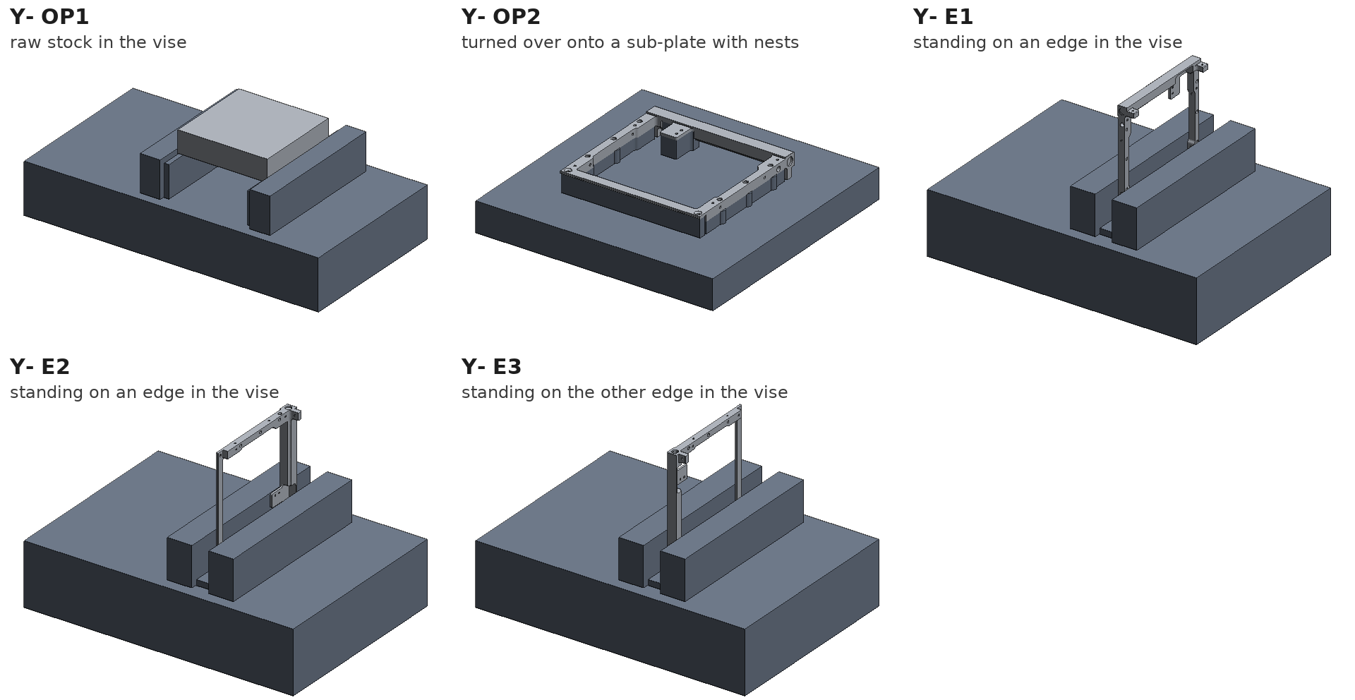
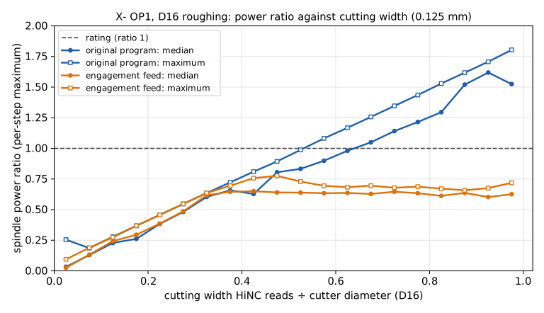
Rendered by HiNC from the TU Wien Space Team's models (CC BY 4.0) with the set-up Tech Coordinate's agent built. The structure and the clampings are the agent's own renders of the models, and the two charts are drawn by its scripts from HiNC's readings.
Four of its nineteen dilemmas
Two or three clampings a plate turned out to be twenty-four
The case's outline expected two or three clampings a plate on a three-axis machine. Merging the STEP's cylinder faces into holes gave hole axes along X and Y as well: the side panels carry M2 and M4 tap drills, the D5.5 H7 seats of the spring plungers and a stepped bore in their end faces and one edge, which two clampings would have left undrilled. Each side panel gained three clampings standing in the vise; the batch became 2 × 2 + 4 × 5 = 24, the edge programs holding drilling, opening out and reaming only.
A shank the agent's check did not see
At a 1 mm cell, HiNC reported 446 collisions of a cutter's shank with the workpiece in plate Z-'s first clamping. The agent measured how far each piece of the cutter stays from the design part along the path: the 2 mm ball's neck was 12 mm long, so its 4 mm shank began 12 mm above the tip and ran 0.97 mm into the 21.8 mm tab, where its own check had taken the neck's radius all the way up. The check now takes the cutter in pieces, and the neck became 16 mm. All 121 points along the groove then pass; with the old neck 66 passed, and the 55 that failed are where HiNC had reported the collisions.
Programs that ran clean and still overloaded the cutters
Played whole on plate X- at a 0.125 mm cell, the original programs drew no message and over-cut at most 0.019 mm. Yet the D16 roughing asked the spindle for 1.61 times its rating at the 99th percentile, and the finishing bent the D6 194 µm and the D2 360 µm (the same program replayed for its NC optimization). HiNC's per-step readings showed where: the ratio passed 1 only where the D16 met more than 0.55 of its diameter at full depth, and a floor pass took the walls' 0.3 mm allowance over their whole height. The agent scaled the feed to the stock each piece of path meets over the flute length and finished walls in two passes; on a trimmed play the roughing read at most 0.78 and the D6, D4 and D2 final passes 23.6, 11.2 and 23.9 µm.
Sheets that would sag between screws
Held only by pads under the M3 holes, the side panels' 1.6 and 1.8 mm sheets would span 20–40 mm in the second clamping, and a strip model puts 20 N of axial force at about 0.1 mm of sag, twice the sheets' ±0.05 mm. The agent shaped the sub-plate into nests under the first clamping's face and the sheets, 0.3 mm inside their edges and clear of wherever the part reaches lower. With HiNC's axial forces in the same model, the sheets on their nests sag 0.003–0.12 µm.
The other fifteen are in the full record, among them a reference mesh with a fan of triangles across the window, blind holes that break through, rail coves a 2.5-axis path cannot make, deeper walls that needed longer cutters and a fresh plan, and a feed slowed round inside corners.
The result
At a 0.125 mm cell all 24 clampings ran to the end, 2,838,462 steps, each later clamping starting from the workpiece the one before left, with no collision. The holders cleared everywhere; in a negative control at a 1 mm cell, held 6 mm shorter than it needs, the 2 mm cutter drew HiNC's holder collision at the place the plan named. On the revised programs the finishing cutters bend at most 23.1 µm on the D6 walls (limit 25), 37.6 µm with the D4 and 48.5 µm with the D2 in corners (limit 50), except one step at 55.8 µm (Y+ OP1's 2 mm stage replayed for the NC-optimization page); the roughing stays at or below 0.90 of the spindle's rating except one step at a ramp reversal. On each plate 96–98 % of the finished surface lies within one cell of the design; Y+ and Z+ keep 4 mm of stock at the rail ends, which the plan had reported beforehand as out of reach of the chosen cutters. HiNC gives 19.0 to 29.1 minutes a plate and 139.5 minutes for the six (the agent's arithmetic: 134.5), 6.3 hours with 10 minutes assumed for each clamping; the revision made the planned machining 38 % longer. Of the fourteen criteria with a pass mark written before the first play, eight held. The six that did not are reported as failed: messages in four edge clampings, drill stress readings that contradict each other, one step of the D2, one ramp-reversal step, over-cuts 3–34 µm past one cell along inside edges on four plates, and edge drilling times against arithmetic that took the peck clearance as zero. Everything is simulated; no plate was cut.
| Key number | What it is |
|---|---|
| 2,838,462 steps | HiNC's play of the 24 clampings at a 0.125 mm cell, each later clamping starting from the workpiece the one before left; no collision |
| 1.61 → 0.90 | the D16 roughing's spindle power ratio: the original programs' 99th percentile on plate X-, and the revised programs' highest on any plate but one ramp-reversal step |
| 194 → 23.1 µm | the D6's largest finishing deflection: the original programs on plate X-, the revised ones on all six plates (limit 25) |
| 360 → 48.5 µm | the same for the D2 in corners (limit 50); one step on Y+ reads 55.8 |
| 96–98 % | of each plate's finished surface within one 0.125 mm cell of the design |
| 139.5 min | HiNC's machining time for the six plates' 24 programs, against the agent's arithmetic of 134.5; 6.3 h for a set with 10 min assumed for each clamping |
| +38 % | the revision's price: the planned machining from 97.2 to 134.5 min |
| about 140 min | the plays of all 24 clampings on a shared 32-thread server, one plate at a time (20–31 min a plate) |
| 8 of 14 | criteria with a pass mark written before the first play that held; the six that did not are reported as failed |
NC optimization of this case →
What it brought
- For a machining engineer: before any aluminium was cut, a roughing past the spindle's rating wherever the D16 met more than 0.55 of its diameter at full depth, floor passes that took a wall's whole allowance, small cutters bending 194–360 µm, and a ball's shank cutting into a tab; stick-outs that clear; 6.3 hours for a set of six plates; and the 4 mm of rail-end stock the chosen cutters cannot make.
- For a teacher or a student: a complete multi-clamping plan for thin aerospace plates: counting clampings from the holes' axes, using the drawing's M3 holes to hold the part when it is turned over, nests under 1.6 mm sheets, an end-cutting reamer for flat-bottomed H7 bores, a feed scaled to the stock the cutter meets, walls finished in two passes, and a cutter held deliberately short to prove the holder check runs.
- For someone deciding whether to use an agent with HiNC: from STEP models and drawings, with no CAM program to start from, to 24 programs revised round by round against HiNC's per-step loads, contact counts and exported parts, and judged against criteria fixed before the first play; the six criteria that failed are reported as failed. No second agent rebuilt the case.
Read the full case record: SpaceTeamSat1 CubeSat structure
The source and its backup
| Case | Original files | Backup |
|---|---|---|
| SpaceTeamSat1 CubeSat structure | The team's Zenodo record (STEP models and drawings) | Showcase-STS1-CubeSat-Structure.zip |
The zip holds the case's SOURCE.md, which states what was
changed; the team's archive Sts1MechanicalDesign_1.0.zip as published on Zenodo, with the
STEP models and the drawing set; and the agent's work: the numbers file with every tool, holder,
stick-out and pass criterion, each plate's plan, the fixtures, the 24 programs and the acceptance results.
The plates' design meshes and the programs split per tool are left out to keep it small: the meshes are
made from the STEP files, and the split programs are cut from the whole ones.