SpaceTeamSat1 CubeSat Structure: Six Al 7075 Plates, Twenty-Four Clampings, and Whether the Small Cutters Hold Up
SpaceTeamSat1 is the TU Wien Space Team's 1U CubeSat. Its structure is a frame of six plates machined from Al 7075, about 100 mm on a side: two square frames (X±) and four side panels (Y±, Z±) with rails, 1.6–1.8 mm sheets and D4 H7 locating bores. The team published the STEP models and a 13-sheet drawing set under CC BY 4.0. The drawings give the material, the general tolerance ISO 2768-f, the surfaces and the H7 holes; they give no fixture, no order of operations and no tools. An AI agent wrote its own 2.5-axis CAM over the STEP files, with no commercial CAM: it worked out every plate's operations and clampings, chose the cutters and their holders, wrote the Fanuc programs, and built 24 HiNC projects through the web API, each clamping reading the workpiece its predecessor left.
The questions were a shop's: does the holder get into side pockets 15–24 mm deep, do the D2 and D4 cutters hold up beside 1.6 mm sheets and 1.1 mm boss walls, does the part come out as designed, and how long does the batch of six take. On HiNC 3.2.43 at a 0.125 mm cell:
- The holders clear. Every stick-out was sized by a height map of the part grown by the holder's radius, plus 2 mm, and the 24 clampings drew no collision. In a negative control at a 1 mm cell, held 6 mm shorter than it needs, the D2 drew HiNC's holder-against-workpiece collision at the place the plan named.
- The small cutters hold up, after a revision. With the original programs, plate X- failed all three load criteria: the D16 roughing asked the spindle for 1.6 times its rating (99th percentile), and the D6 and D2 finishing bent 193.9 and 359.9 µm (X- OP1's original program replayed on HiNC 3.2.45 for the NC-optimization study). With a feed scaled to the cutting section, walls in two passes, the long cutters planned on their own and a slower feed round inside arcs, the six plates' finishing passes bend at most 23.1 µm on the D6 walls (limit 25), 37.6 µm with the D4 and 48.5 µm with the D2 in corners (limit 50), except one step of the D2 on Y+ at 55.8 µm (Y+ OP1's D2 stage replayed in the same study). The roughing stays at or below 0.90 of the spindle's rating except one ramp-reversal step that reads 2.63.
- The shape. On each plate 96–98 % of the finished surface lies within one cell of the design. The X plates are over-cut by at most 0.026 mm; the Y and Z plates go 3–34 µm past one cell along inside edges; Y+ and Z+ keep 4 mm of stock at the rail ends, which the plan had reported out of reach of the chosen cutters. The ±0.05 mm sheets and boss walls are finer than the cell, so their deflection was computed from HiNC's forces instead: at most 0.12 µm and 0.15 µm.
- The batch. 139.5 minutes of programs in HiNC (the agent's arithmetic: 134.5), 6.3 hours with 10 minutes assumed for each of the 24 clampings.
Of the fourteen criteria with a pass mark written before the first play, eight held; the six that did not are stated with their causes under Results and benefits. Several of those causes are HiNC's own: edge set-ups placed 120° about a diagonal read no force at all, and a few single steps read loads their geometry does not explain.
Everything here is simulated: no plate was cut on a real machine. The pictures are the agent's own renders of the published models, HiNC's canvas and the agent's charts of HiNC's readings; the drawings carry a SolidWorks educational watermark and are not reproduced. Each dilemma below gives the risk, how it came to light, the resolution and the evidence that it held. The built projects were the agent's working material and are not distributed.
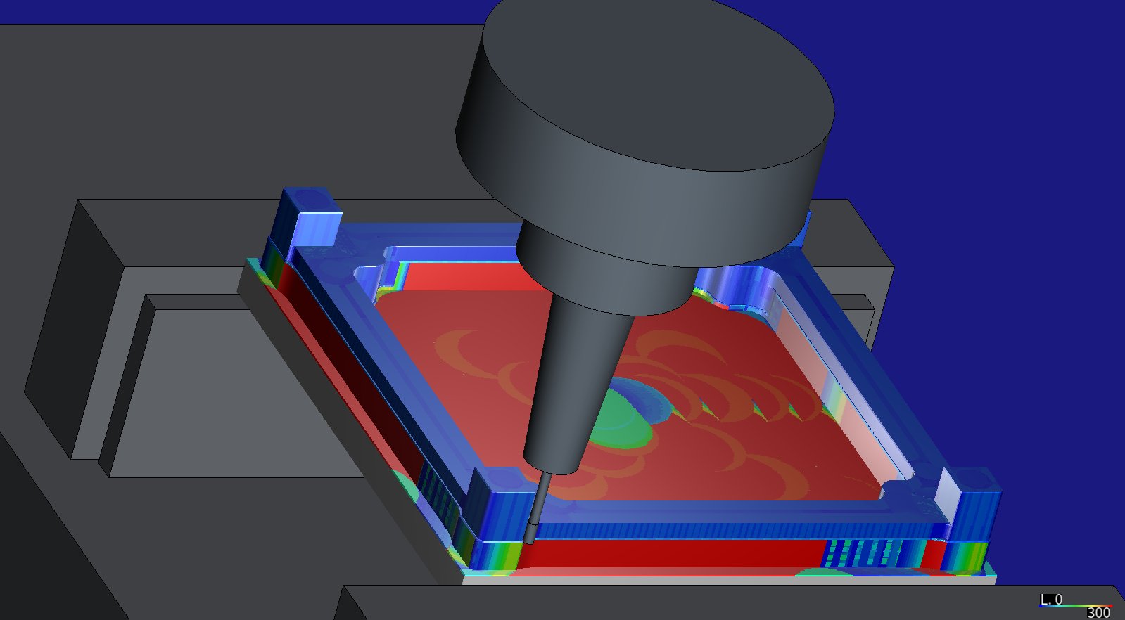
HiNC's canvas: plate X- in the vise, first clamping. The D2 end mill sits 17 mm out of its shrink-fit chuck in an R1 corner 10 mm below the frame's top, and the chuck's nose is still 7 mm above it. The part is coloured by the peak cutting force of the step that cut each face (0–300 N). Captured on HiNC 3.2.43.
The case
The TU Wien Space Team published the satellite's mechanical design on Zenodo: the assembly and the six plates as STEP files, and a 13-sheet drawing set. The drawings state:
- material Al 7075 on every plate; general tolerance ISO 2768-f; the surfaces; the rails hard anodised;
- H7 bores, with “Bei Bohrung D4,00 H7 Benutzung von Stirnreibahle notwendig”: the flat-bottomed D4 H7 bores need an end-cutting reamer;
- “Alle bemassten Bohrungen M3 dienen zur Fertigung”: the dimensioned M3 holes serve the manufacturing.
What they leave out: the stock, the order of operations and the clampings, the fixtures, the machine, the cutters and their holders, the cutting data and the programs.
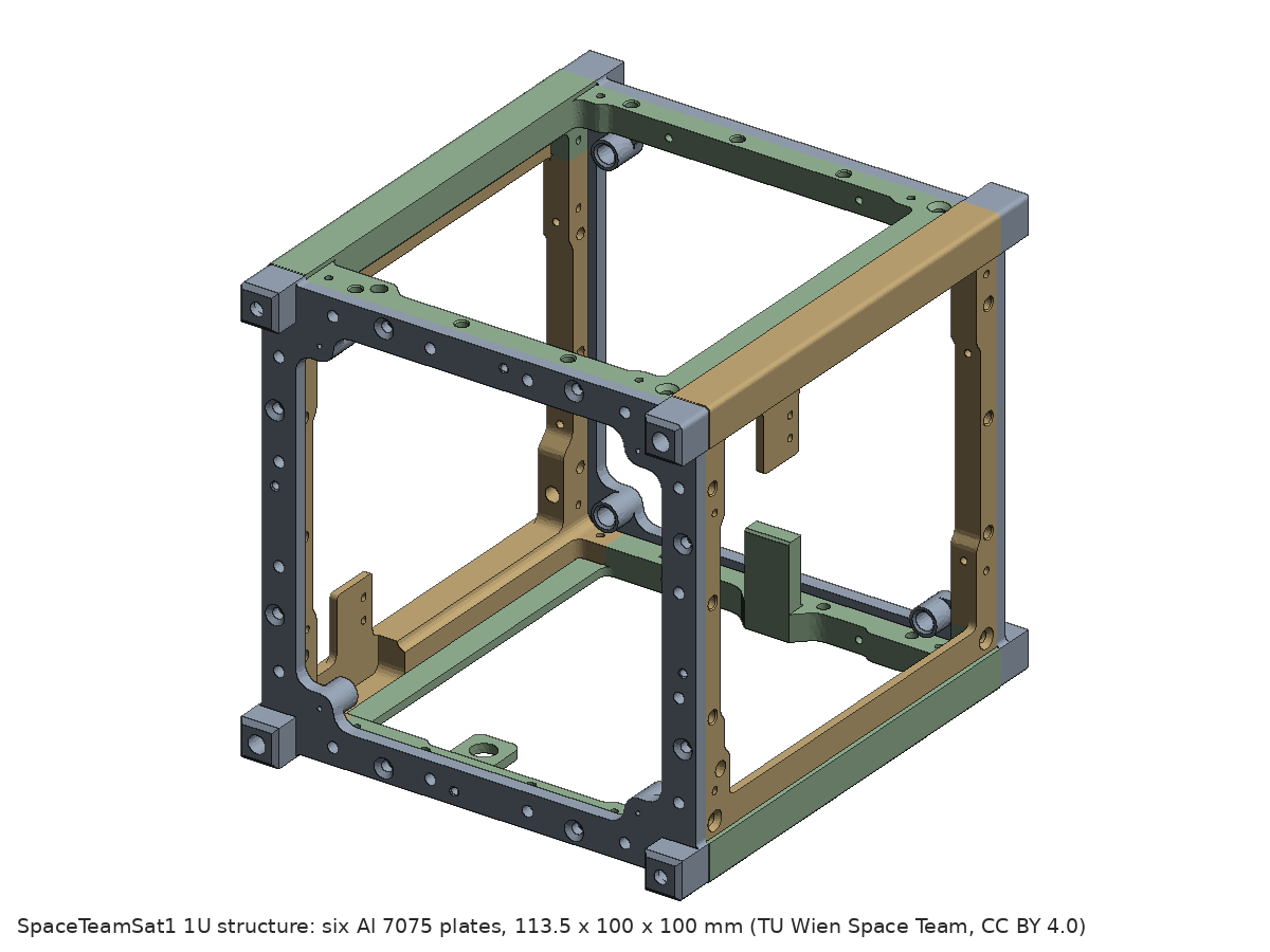
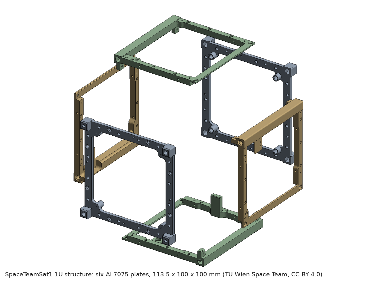
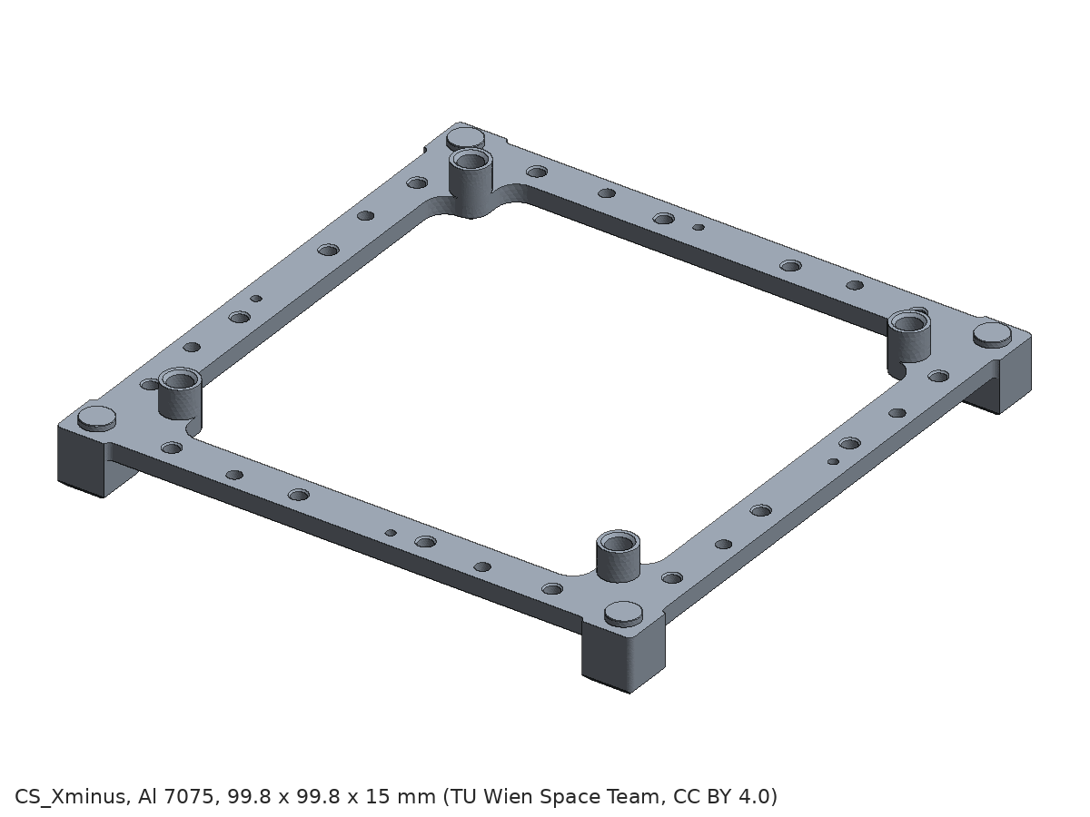
The agent's own renders: meshes it made from the STEP files, ray traced. The drawings are not shown.
| Plate | Size (mm) | Part | Stock (mm) | Removed | Holes | Clampings |
|---|---|---|---|---|---|---|
| CS_Xminus | 99.8 × 99.8 × 15.0 | 11,097 mm³ | 103.8 × 103.8 × 24.0 | 95.7 % | 36 | 2 |
| CS_Xplus | 99.8 × 99.8 × 14.5 | 10,446 mm³ | 103.8 × 103.8 × 23.5 | 95.9 % | 42 | 2 |
| CS_Yminus | 91.4 × 94.0 × 14.9 | 12,057 mm³ | 95.4 × 98.0 × 23.9 | 94.6 % | 25 | 5 |
| CS_Yplus | 91.4 × 94.0 × 14.9 | 12,014 mm³ | 95.4 × 98.0 × 23.9 | 94.6 % | 25 | 5 |
| CS_Zminus | 94.0 × 91.4 × 21.8 | 13,876 mm³ | 98.0 × 95.4 × 30.8 | 95.2 % | 21 | 5 |
| CS_Zplus | 94.0 × 91.4 × 14.9 | 12,555 mm³ | 98.0 × 95.4 × 23.9 | 94.4 % | 21 | 5 |
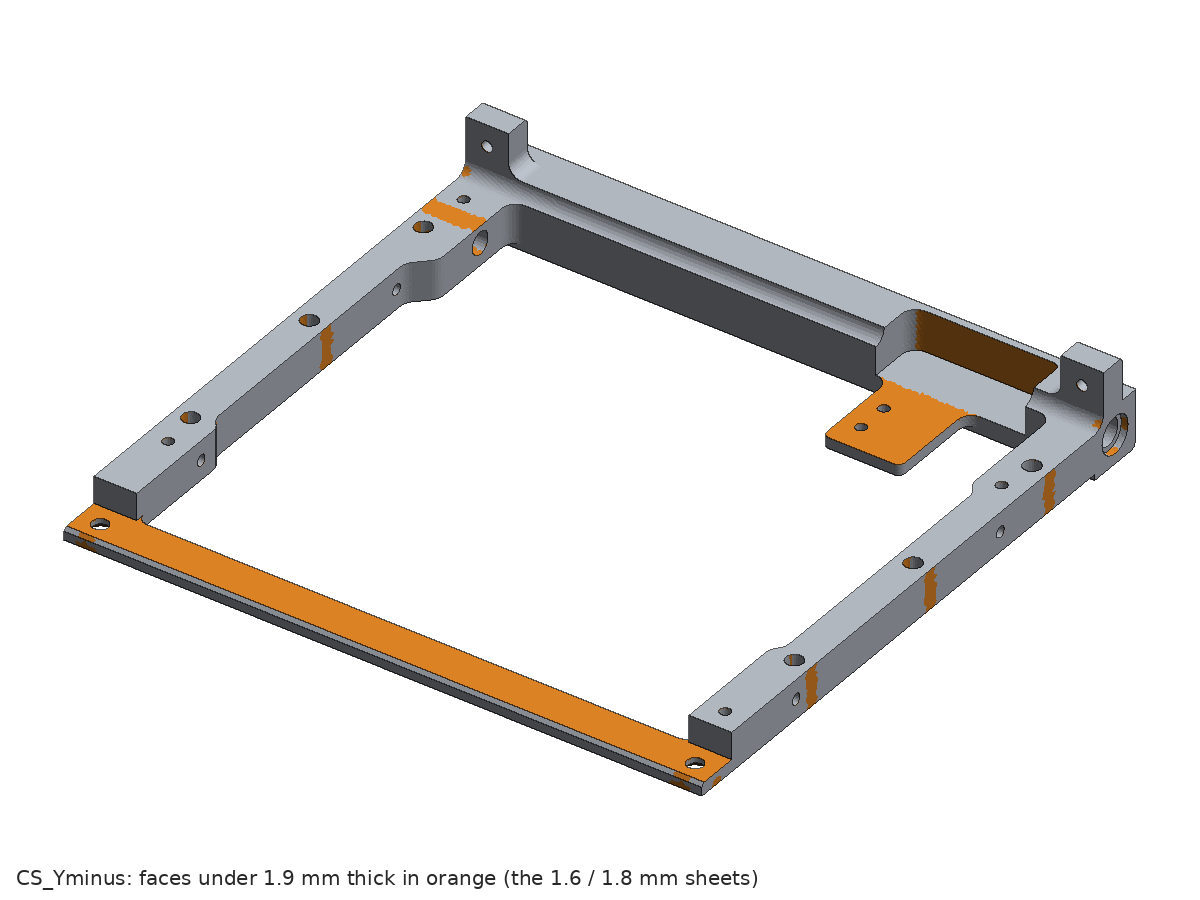
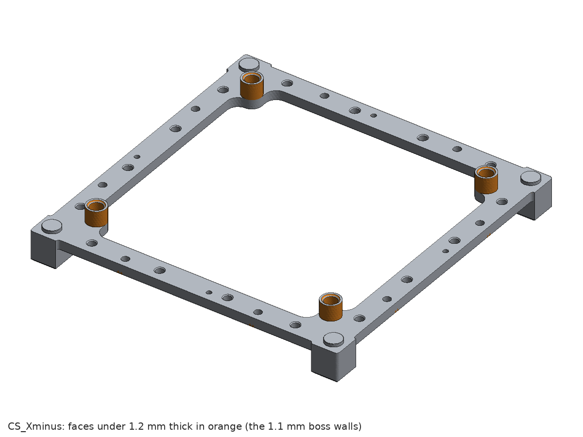
The thin parts, measured on the STEP by a ray from the centre of each face to the face opposite. Above: a side panel's 1.6 mm (about 206 mm²) and 1.8 mm (555–602 mm²) sheets. Below: the X plates' four bosses, D6.2 round a D4 H7 bore, with a 1.1 mm wall 5 mm tall. The “ribs of about 1.2 mm” the case was first described with are these boss walls and a wall of about 1 mm at the end of the Y plates.
What the agent built
Everything went through HiNC's web API, following Project Construction, Driving the Web Service over HTTP and Replay Acceptance over the HTTP API. Each value is marked read (stated by the source), derived (from the STEP), chosen (by the agent where the source is silent) or measured (in a run on HiNC 3.2.43).
| Item | Value | Basis |
|---|---|---|
| Parts | the six plates' STEP models, meshed closed by the agent (gmsh), each in a frame with its thickness on Z | Read; frames derived |
| Material | AA7075, HiNC's library data | Read (every drawing) |
| Stock | the part's box + 2 mm a side, + 1 mm to face, + an 8 mm slab under the far face for the vise to grip 5 mm deep; OP2 mills the slab off | Chosen |
| Clampings | OP1 in a vise on the slab; OP2 turned over onto a sub-plate; on the side panels three more (E1–E3) with the plate standing in the vise: 24 in all | OP1's face read from the M3 note; the edge holes derived from the STEP; the rest chosen |
| OP2 fixture | a sub-plate with screw pads under the M3 holes and, on the side panels, nests shaped to the OP1 face and the sheets, 0.3 mm inside their edges | Chosen: on pads alone a sheet would span 20–40 mm |
| Turning over | each clamping its own project; the same workpiece frame placed turned over by a GeneralTransform on the fixture mount and the program-zero anchor; the mission's first command reads the workpiece the previous clamping recorded |
Chosen, checked on a probe block first |
| Machine | generic three-axis vertical machining centre: travel 800 / 500 / 500 mm, rapids 30 m/min, from the Empty-wXYOZSt skeleton |
Chosen |
| Spindle | the Showcase's generic spindle: 7.5 kW continuous, 10 kW short term, 24,000 rpm, efficiency 0.4 (HiNC's default) | Chosen |
| Controller, program zero | Fanuc; G54 at the centre of the stock's top face in each clamping | Chosen |
| Holders | generic shrink-fit chucks SF3 / SF4 / SF6 / SF16, 80 mm gauge length, nose radius 4.5 / 5 / 10.5 / 16 mm, after the general proportions of DIN 69882-8, defined in the project as Z–R profiles | Chosen |
| Stick-out | the longest of: the holder's clearance need (the part's height map in that clamping, grown by the holder's radius at its nose and 10, 20 and 30 mm up, plus 2 mm), the flutes + 1 mm, the neck + 1 mm; rounded up to 0.5 mm | Chosen; a necked cutter never sits shorter than its neck, which the chuck does not grip |
| Programs | the agent's own 2.5-axis CAM: offset-contour roughing with helix and zig-zag ramp entries, rest roughing with the smaller cutters, floors, then each wall in two passes per level (a semi-finish leaving 0.1 mm, the final pass), ball-end passes along the rails' coves, peck drilling (G83) and end-cutting reaming; the feed scaled to the cutting section each piece of path meets | Chosen |
| Resolution | 1 mm for the first check of all 24, the early trimmed cases and the holder's negative control; 0.5 mm for the probes and one sweep; 0.125 mm for the later trimmed cases and the acceptance | Chosen (Mesh Resolution) |
| Play | one tool per run: each program split at its tool changes, 126 stages for the 24 programs | Chosen |
| T | Cutter | Flutes / neck (mm) | Out (mm) | Holder | Speed, feed per tooth | Use |
|---|---|---|---|---|---|---|
| T1 | D16 three-flute end mill | flutes 32 | 33 | SF16 | 15,000 rpm, 0.08 | facing, roughing (ap 4, ae 6.4) |
| T2 | D6 three-flute end mill | flutes 20 | 21 | SF6 | 20,000, 0.04 | rest roughing, floors, walls' semi-finish and final pass (final pass at 80 % feed) |
| T9 | D6 three-flute end mill, long flutes | flutes 26 | 27 (Z- OP1 only) | SF6 | 20,000, 0.04 | Z-‘s deep walls: rest roughing ap 1.5, finishing 1 mm a level, final pass at 60 % feed |
| T3 | D4 three-flute, neck D3.6 × 18 | flutes 8 | 19 | SF4 | 24,000, 0.025 | R2 corners |
| T8 | D4 three-flute, neck D3.6 × 25 | flutes 8 | 26 (Z- OP1 only) | SF4 | 24,000, 0.025 | R2 corners deep in Z- |
| T4 | D2 two-flute, neck D1.8 × 16 | flutes 4 | 17 | SF4 | 24,000, 0.012 | R1 corners and narrow slots |
| T5 | D4 ball end, neck D3.6 × 16 | flutes 8 | 17 | SF4 | 20,000, 0.03 | the rails’ R2 coves (three passes, 50 % feed) |
| T6 | D2 ball end, neck D1.6 × 16 | flutes 3 | 17 (Z- OP1 only) | SF4 | 24,000, 0.015 | the R1 groove at the foot of Z-'s tab (six passes, 25 % feed) |
| T11–T18 | carbide drills D1.0, 1.6 (M2), 2.4, 2.5 (M3), 2.8, 3.3 (M4), 3.8, 5.5 (M6 × 0.5) | — | 9–29 | SF3 / SF4 / SF6 | by diameter | holes, tap drills, pre-ream holes |
| T21–T23 | H7 end-cutting reamers D3.0, 4.0, 5.5 | — | 11–15 | SF3 / SF4 / SF6 | 1,800–3,000 rpm | H7 holes; the circular milling before the D5.5 seat leaves 0.3 mm on the diameter |
The cutting data are common starting values for carbide in 7075, the agent's choice, not a maker's table.
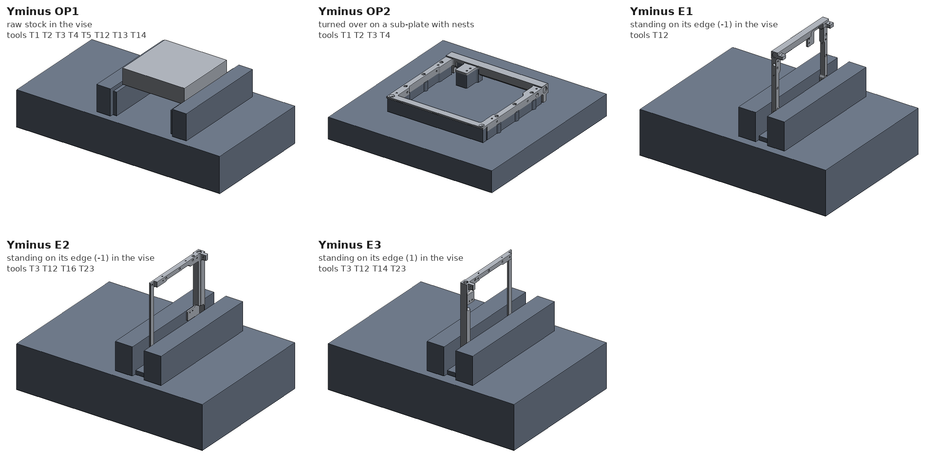
A side panel's five clampings, the agent's render of its fixtures. OP1 makes the face the M3 holes open on; OP2 turns the plate over onto nests shaped to that face and the sheets and screws it down through the M3 holes from below; E1–E3 stand the plate up to drill the two end faces and one edge. The X plates have OP1 and OP2 only.
Each clamping, what holds the plate and what it machines:
| Clamping | Held by | What it machines | Basis |
|---|---|---|---|
| OP1 | the vise, gripping the stock's 8 mm slab 5 mm deep | facing, roughing, rest roughing, semi-finishing and finishing, the coves, and the holes in the face the M3 holes open on | that face read from the drawings' M3 note; the vise chosen |
| OP2 | turned over onto a sub-plate: screw pads under the M3 holes and, on the side panels, nests shaped to the OP1 face and the sheets, 0.3 mm inside their edges | the slab milled off, the far face, the holes in that face and the H7 bores | Chosen; the nests because on pads alone a sheet would span 20–40 mm |
| E1–E3 (side panels only) | the plate standing in the vise, gripped by its two large faces | the holes in the two end faces and one edge: M2 and M4 tap drills, the D5.5 H7 seats and a stepped bore | Derived: the STEP's hole axes along X and Y |
How the agent managed the work
- Pass criteria before the first play. Written into the case's
Setup/case-numbers.jsonand committed before HiNC played anything, in five groups: A a clean run (every line, steps that touch, no warning or error, each clamping reading its predecessor); B the holder (stick-outs at least the clearance need, no collision, and a negative control); C the cutters and the part (stress ratio below 0.5 for cutters of D4 and under and 0.8 for all, tip deflection at most 25 µm on D6 and D16 walls and 50 µm in D4 and D2 corners, the thin sheets and boss walls under HiNC's force at most 12.5 µm, spindle power and torque below their rating); D the finished part against the design within one cell, and an error budget against the tolerance; E each program's time within ±3 % of the agent's arithmetic, and the batch. A script judges the acceptance against the text as written; every rule it needed that the text did not state is marked as set afterwards. - Small before large. All 24 clampings ran first at 1 mm. Plate X- then ran whole at 0.125 mm with the original programs, and failed. Every revision after that was checked first on a trimmed play (the finishing alone, started from the workpiece recorded after the roughing, one to two minutes each) or on a single clamping played ahead, before the next step; all 24 swept once at 0.5 mm; then the acceptance, one plate at a time.
- Every operation must touch. The acceptance checks the contact of every operation in every play, and the case plays one tool per run.
- Watched while it played. A read-only watch reported each finished stage and any error as the acceptance ran, and at intervals the alarm counts, the share of touching steps and the load peaks.
- A shared server. The CAM planned a clamping in about 20 seconds on a 32-thread server, against more than six minutes on a workstation saturated by three sessions' CAM runs; the plays ran there too, on a private instance. The acceptance took a lock shared with other cases' acceptance one plate at a time and gave it up twice in between; with the server's other load the plays ran at 25 to 1,100 steps a second.
- Where a person stepped in. The record names none. No second agent rebuilt the case from its record.
The dilemmas
Unless a dilemma says otherwise, its numbers were measured on HiNC 3.2.43.
Two or three clampings a plate turned out to be twenty-four
- Situation. The case's outline expected two or three clampings a plate on a three-axis machine.
- Risk. Holes in the side panels' end faces and one edge left undrilled: M2 and M4 tap drills, the D5.5 H7 seats of the spring plungers, a stepped bore.
- How it was noticed. Merging the STEP's cylinder faces into holes gave hole axes along X and Y.
- Resolution. Three more clampings per side panel (E1–E3) with the plate standing in the vise; the X plates keep two. 2 × 2 + 4 × 5 = 24 clampings for the batch.
- Evidence it held. 24 projects; the edge clampings' programs hold 21–469 lines each, of drilling, opening out and reaming only.
Which face first
- Situation. The drawings give no order of operations.
- Risk. An OP2 with nothing to hold but the outline, clamping across a 1.6 mm sheet.
- How it was noticed. The drawings' note that the dimensioned M3 holes serve the manufacturing.
- Resolution. OP1 machines the face those M3 holes open on; OP2 turns the plate over onto a sub-plate and screws it down through them from below.
- Evidence it held. Every OP2 fixture carries screw pads under the M3 holes.
A mesh with a fan across the window
- Situation. Tessellated with an open-source STEP reader at its default tolerance, the X plates came out with the frame's large face triangulated in a fan across the open window.
- Risk. A design model of 26,382 mm³ against the part's 11,096: every comparison would read the whole window as uncut. The first preview pictures of the case showed exactly that fan.
- How it was noticed. The mesh was not closed, and its volume was more than twice the part's.
- Resolution. A conforming mesh from gmsh.
- Evidence it held. Closed, 11,097.4 mm³ (+0.015 %); every render on this page is made from it.
Blind holes that break through
- Situation. The M2 and M3 cylinders stop 0.2–0.3 mm short of the far face.
- Risk. Drilled as blind holes, they would need a second, aligned drilling from the far side in OP2.
- How it was noticed. Each cylinder ends in a 45° cone (a 90° drill point) whose tip breaks through the far face.
- Resolution. Through holes, drilled from one side in OP1.
- Evidence it held. At 0.125 mm the finished parts keep only the points of these holes, 0.15 to 0.19 mm proud (the agent's drills have a 140° point).
Turning a part over in HiNC
- Situation. A play knows one clamping; the session has no set-up change.
- Risk. OP2 cutting from fresh stock, with OP1's features gone.
- How it was noticed. A probe showed that a recorded workpiece is stored in the workpiece frame.
- Resolution. Each clamping is its own project; the same workpiece frame is placed turned over by
a
GeneralTransformon the fixture mount and the program-zero anchor, and the mission's first command reads the predecessor's record. - Evidence it held. On a probe block, OP1 cut a slot along X on top and OP2 one along Y from below; the exported part shows both. In the acceptance every one of the 20 later clampings read its predecessor and touched material within 3 to 106 steps, and plate X-'s exported part matches the design on OP1's side (overlap 0.9998) and not on the mirrored side (0.0).
Coves a 2.5-axis path cannot make
- Situation. The rails' R2 relief and an R1 groove at the foot of Z-'s 21.8 mm tab are concave cylinders with horizontal axes.
- Risk. The residual report left 150–230 mm³ per side panel in them.
- How it was noticed. The residual report of the agent's CAM.
- Resolution. A ball-end cutter of the cove's diameter with its centre along the cylinder's axis. The first version had a shank as wide as the ball, which hit the cove's upper edge; the second, a neck widening from 4 mm, passed 0.2 mm from a rail's end block and drew 248–695 shank collisions in the trimmed plays at 1 mm. The cutters became a D4 ball with 8 mm of flute on a D3.6 neck and a D2 ball on a D1.6 neck.
- Evidence it held. See the next dilemma: this version's check still missed the shank.
A shank the first check did not see
- Situation. At 1 mm, Z- OP1 reported 446
Collided(Workpiece,CutterShank)and Y+ OP1 250. - Risk. Waving both off as the coarse grid, and meeting them in the acceptance.
- How it was noticed. Before the acceptance the agent measured, piece by piece, how far the design part was from the cutter at every recorded collision.
- Resolution. Y+'s came from a project built with an earlier ball-end cutter (4 mm of flute); rebuilt with the current one, its 1 mm play was clean. Z-'s were real: the D2 ball's neck was 12 mm long, so its D4 shank began 12 mm above the tip and ran 0.97 mm into the tab, because the check had taken the neck's radius all the way up. The check now takes the cutter in pieces (the ball and fluted cylinder may touch only the cove; the neck and shank keep 0.1 mm off the part), each cylinder sampled by 24 points round it. The distance from one point on the axis to the mesh is a sphere test, and it read the edge below the shank as a hit, which dropped the whole R1 groove in the first rewrite. The D2 ball's neck became 16 mm long.
- Evidence it held. With the 16 mm neck all 121 points along the groove pass; with the old 12 mm neck 66 pass, and the 55 that fail are where HiNC reported the collisions.
Faults in the agent's own CAM, caught before the acceptance
- Situation. The agent's offline over-cut check, its path lengths and the 1 mm plays of all 24
clampings found faults in its own programs:
- a helix entry whose centre was off by one helix radius, over-cutting a boss's edge by 1.43 mm;
- rest machining whose allowance shrank from 0.3 to 0.1 mm, so every wall was cut twice;
- stock layers whose bounds were rounded to five decimals, so a layer 3·10⁻⁵ mm off was never subtracted: floors kept 0.15 mm, and X OP2 thought the window's material was still there;
- an R1 corner of the outline (an 84° arc whose centre lies 0.1 mm outside it): as half a hole it would have been missed, and as a corner the rest roughing, unable to enter it with its 0.3 mm allowance, ran 12.7 m of air path in 8 places;
- the edge clampings' R plane set at the design hole bottom, and counterbores entered at milling feed;
- a rapid down to a ramp's start whose edge grazed a corner of the stock (
Play-RapidCut--Detected); - the tool length offset left active through a tool change;
- a D1.9 neck 0.05 mm from a wall at 1 mm; and zero-volume rapid cuts in the edge clampings' drilling cycles.
- Resolution. Each was fixed in the CAM before the acceptance. Among the rules that came of
them: the R1 corner is a corner the D2 just fits, and fragments under 1 mm² a level are left to
finishing; every descent comes in two stages (rapid to 1 mm above, then feed); every operation ends
with
G91 G28 Z0.andG90 G49; the necks are D1.8 and D3.6, and finishing runs only where there is a wall; the drilling R plane sits 2 mm above the hole's mouth. - Evidence it held. X- OP1's D2 rest roughing went from 12.7 m of path to none and X OP2's feed time from 953 s to 274 s; in the acceptance 20 clampings play clean and none reports a collision.
A negative control for the holder
- Situation. “No collision message” proves nothing if the check is not running.
- Resolution. The D2 end mill held 12 mm out where the agent's height map then needed 14.4: HiNC
reported 1,000
Collided(Workpiece,ToolHolder), the first at (39.5, −50.0, −13.4), the mirror image, in the turned-over frame, of the place the map named, (38.8, 50.0, −13.4). On the accepted programs, at a 1 mm cell, where the map needs 12 mm, the same cutter held 6 mm out (6 mm short, as the criterion asks) drew 29,493 collision messages, the firstCollided(Workpiece,ToolHolder)in the semi-finishing pass at (50.1, −39.12, −7.0): the XY the plan names as this cutter's tightest place, (50.1, −39.12, −11.0), at the height where the holder first meets the stock on the way down. - Evidence it held. HiNC checks the holder against the workpiece, and it agrees with the agent's map on where the holder would hit.
Sheets that would sag between screws
- Situation. With pads only under the M3 holes, the side panels' 1.6 and 1.8 mm sheets span 20–40 mm in OP2.
- Risk. A strip model puts 20 N of axial force at about 0.1 mm of sag, twice the sheet's ±0.05 mm.
- Resolution. The OP2 sub-plate carries nests shaped to the OP1 face and the sheets, 0.3 mm inside their edges and clear of wherever the part reaches lower.
- Evidence it held. With HiNC's axial forces in the strip model, the sheets on their nests sag 0.003–0.12 µm: the nest lies right under each sheet and the span left is at most 1.5 mm.
The original programs overloaded the spindle and bent the small cutters
- Situation. Plate X- ran whole at 0.125 mm with the original programs: both clampings clean of messages, over-cut at most 0.019 mm. But in X- OP1 the D16 roughing read a spindle power ratio above 1 on 5,844 steps (99th percentile 1.61; one ramp turn 2.63), the D6 finishing a stress ratio of 0.91 and a tip deflection of 193.9 µm, the D2 0.82 and 359.9 µm (the deflections as the same program reads when replayed on HiNC 3.2.45 for the NC-optimization study). Criteria C5, C1 and C2 failed.
- Risk. Running the other five plates with the same programs overnight, to fail the same way.
- How it was noticed. The per-operation peaks of the acceptance; then X- OP1's roughing replayed on a second instance, keeping each step's cutting width, depth, removal rate and power.
- Resolution. The power ratio went above 1 only where the D16 met more than 0.55 of its diameter at the full 3.5 mm depth: the first ring of a pocket, the corners. HiNC's ratio is the cutting power over the spindle's efficiency over its short-term rating; with the library's AA7075 data at about 2.2 J/mm³ at 40 % engagement and an efficiency of 0.4, it reads about five times a usual shop estimate. The D2's 359.9 µm matches a cantilever of its D1.8 neck, 21 mm out, under 42 N. The other five plates' original acceptance was stopped, the programs were revised, and X-'s original result was kept as the “before”.
- Evidence it held. On a trimmed X- OP1 play the revision read at most 0.78 on the roughing and 23.6, 11.2 and 23.9 µm on the D6, D4 and D2 final passes.
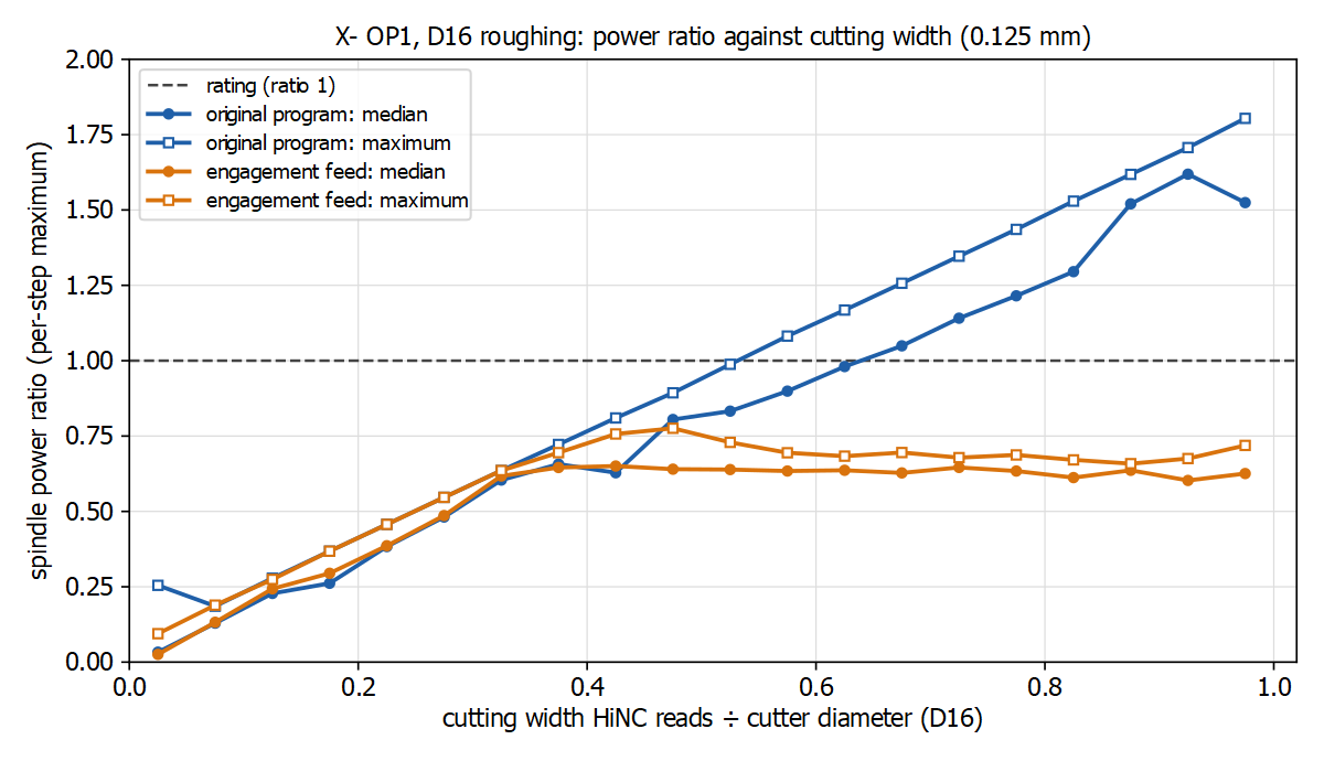
Full-depth steps (3.5 mm) only, on HiNC 3.2.43 at 0.125 mm. Original program in blue; feed scaled to the cutting section in orange.
The load of a finishing pass stood above its own layer
- Situation. The first engagement feed looked only at the layer a pass cut; the D6 still read 333.6 N and 228 µm at a boss's foot, the original program's force at the same place.
- How it was noticed. HiNC read that step as 2.55 mm wide and 4 mm deep: the floor pass, which came to 0.05 mm of the walls, took their 0.3 mm allowance over their whole height, where the model saw a layer 0.16 mm thick.
- Resolution. The engagement model became a raster of the thickness of all the stock within the flutes' reach. Floors keep the walls' 0.3 mm; each wall takes a semi-finish leaving 0.1 mm and a final pass taking it; at a corner the final pass is measured by the arc the cutter's edge meets times its height, over a 0.3 mm window so that the short moves round a corner are not read as nothing on a 0.05 mm raster. Finishing depths became 3 mm for the D6 and 0.6 mm for the D2. On a straight wall, one pass taking 0.3 mm had bent the D6 38 µm and the D2 67 µm (99th percentile).
- Evidence it held. Six trimmed rounds, each the finishing alone on the recorded roughing, one to two minutes each: the D6's largest final-pass deflection went 228, 141, 58.8, 33.8, then 23.6 µm.
The engagement raster's own two faults
- Situation. A pre-run of Z- OP1 had the D16 cut a band 3.95 mm deep and 0.9 D wide at full feed (power ratio 1.87), and a 0.1 mm finishing band sometimes read 0.2 to 1.5 times its width, with cells of stock at the wall that were not there.
- How it was noticed. HiNC's cutting width and depth at the peak step against what the agent's model had predicted for the same stretch of path.
- Resolution. The first raster drew every polygon of a layer into one image with an image library, so a hole drawn later erased an island drawn inside it (the stock ring's hole wiped the material in the window), and the library truncated vertices to whole pixels and filled both edges of a band. The raster became an even-odd scanline per polygon, combined afterwards, a cell counting when its centre is inside, the same rule the model's own cut uses.
- Evidence it held. On a toy shape (a ring with a rotated hole, an island in the hole and a 0.1 mm band) no cell differs from a point-in-polygon test, and the band reads 0.1 / 0.05 cells times its length.
Deeper walls need longer cutters and a fresh plan
- Situation. Plate Z-‘s walls are deeper than the other plates’. The short-neck D4 (neck 18) and
D2 (neck 16) and the D6 with 20 mm of flute cannot reach the bottom; the programs switched to a D4
with a 25 mm neck, a D2 with a 21 mm neck and a D6 with 26 mm of flute. The first version only
swapped the tool numbers and kept the short cutters' 3 mm finishing depth. A pre-run also reported
139
Collided(Workpiece,CutterShank), all in the D6 finishing: with the tip at z −21.5 the shank above the 20 mm flute ran along the top 0.5 mm of a wall, because the reach check had asked only whether the flute covered the depth to be cut. - Risk. A long cutter bends with the cube of its stick-out; the short cutter's depths on it double the deflection or worse.
- Resolution. The CAM plans each plate with the short cutters first, finds every cutter whose tip goes deeper than it can reach, and plans the whole clamping again from the same stock with the long versions and their own depths and widths; a clamping in which a flat cutter still cannot reach stops the build. A cutter without a neck is judged by its flute length, and the D6 with 26 mm of flute (T9) is Z- OP1's long D6.
- Evidence it held. The same clamping then played with no collision. In the accepted programs Z- OP1 is planned with the long D4 (T8) and the long D6 (T9); the D2's paths there stay within its 16 mm neck, so the D2 with the 21 mm neck was not needed.
A strip left over the rail coves
- Situation. Over the rails' concave rounds (the coves) a strip of stock stayed for the ball-end cutters, which took it with their whole 8 mm of flute: stress ratios 0.84 (D4) and 1.18 (D2).
- Resolution. The roughing levels were a fixed step that skipped the height of the coves' axes, so that strip was left to the ball. The coves' axis heights joined the roughing and finishing levels; the D4 ball takes each cove in three passes at 50 % feed and the D2 ball in six at 25 %, leaving by feed rather than rapid; and the whole cutter (ball, fluted cylinder, neck and shank) is checked against the part height by height.
- Evidence it held. The D2 ball's largest deflection fell from 125 to 48.5 µm.
The long D6 on straight walls and in inside corners
- Situation. The 26 mm-flute D6's final pass on Z- bent 22.5 µm at the median and 28.7 µm at the 90th percentile; halving its finishing depth from 2 mm to 1 mm left the median where it was.
- How it was noticed. The steps grouped by the cutting depth and width HiNC read: most were a 1.0 mm by 0.1 mm cut at 18.9 N and 28.7 µm, about 1.52 µm per newton at 27 mm out of the chuck, and a straight wall's feed was already 100 %, so a smaller depth changed nothing step by step. The largest, 49–73 µm, sat at 17 points, the same XY at every level: the cutter's centre path rounding an inside corner at about 3.2 mm radius, where HiNC read 0.21–0.35 mm of width and 32–49 N at full feed.
- Resolution. This cutter's final pass runs slower (70 % at first, 60 % in the accepted programs; the short D6's final pass 80 %), and every finishing path slows round an inside arc to ρ / (ρ + r) of its feed, ρ the centre path's radius and r the cutter's, so the feed at the cutting edge stays the programmed one: the usual CAM rule.
- Evidence it held. On a toy pocket with R6.2 inside corners the D6 slows to 0.516 in the corners and keeps full feed round a boss. In the acceptance the long D6's final passes bend at most 23.1 µm.
Path pieces too short to read: a 0.034 mm ramp leg and 0.002 mm segments
- Situation. One step of Z- OP1's D16 roughing read a spindle power ratio of 2.63, with the 99.9th percentile at 0.71. Later, with the changes above, the long D6's final pass on Z- OP1 bent 16.3 µm at the median and 20.7 µm at the 99th percentile, but 17 steps still passed 25 µm, up to 52 µm, at the same few XY on every level.
- How it was noticed. The zig-zag ramp runs back and forth along a path's first 15 mm; that 15 mm had ended 0.034 mm past a vertex, so the ramp turned round on a 0.034 mm leg. On the D6, HiNC's cutting width step by step read 0.35 mm at the worst step and 0.15 and 0.10 at its neighbours, while the semi-finish had taken its 0.2 mm there, so the allowance was right; every step above 25 µm sat on a program segment 0.0014–0.0028 mm long (one 0.038 mm) on a nearly straight run.
- Resolution. The offset contours carried near-zero segments, and HiNC's reading on such a step is not steady. Ramp legs are now at least 0.5 mm, and every cut path drops a point closer than 0.05 mm to the one before it and within 2 µm of the line through its neighbours; corners and the last point stay, so the shape does not change. An NC post-processor would do the same. The plates' programs lost 5,000 to 21,000 lines, with no change in feed time.
- Evidence it held. Those steps did not come back. A step of a related kind remains in the acceptance: a ramp reversal in X- OP1's roughing reads a removal rate of 6,031 mm³/s between neighbours of 1,090 and 283, and a power ratio of 2.632, where every other step stays at or below 0.90. It is recorded as a HiNC reading, not changed in the program.
Drilling times twice the arithmetic
- Situation. Criterion E1 asks HiNC's time for each program within ±3 % of the agent's arithmetic. Of 120 operations the milling came out at a ratio of about 1.000; 27 peck-drilling operations came 1.2 to 2.7 times longer.
- How it was noticed. Following one hole's peck cycle step by step.
- Resolution. HiNC's G83 follows Fanuc's cycle, but takes the clearance d from its Fanuc table's parameter 4002, 5 mm by default: every peck after the first feeds from 5 mm above the last depth, so at Q 2 mm each peck feeds 5 mm of air. The agent's arithmetic had taken d as 0 (rapid back to the last depth). The parameter was left alone: a real machine's clearance is the builder's small value, and it moves only time.
- Evidence it held. With d = 5 mm in the arithmetic every drilling operation matches HiNC within 0.3 %. E1 is still judged as registered, with d = 0, and fails on eight edge programs.
Edge set-ups placed 120° about a diagonal read no force
- Situation. In the Z plates' E1 and E2 clampings the D4 circular milling of the D5.5 H7 seats read
no cutting width, no force and no removal, and the end-cutting reamer touched nothing
(
Play-Touch--None). - Risk. Read literally, the four reaming passes fail criterion A, and every force, stress ratio and deflection of those clampings is zero, so criterion C measures nothing there.
- How it was noticed. A reaming allowance raised from 0.2 to 0.3 mm on the diameter, more than a cell, changed nothing, so the grid was not the cause. The edge clampings side by side were: those placed 90° about X or 180° about (0, 1, 1)/√2, with the tool along the part's Y (Y± E2 and E3), read normal forces and removal; those placed 120° about a diagonal, with the tool along the part's X (Z± E1 and E2, Y± E1), read zero force at every step, drilling included. The design has the seats there, no OP1 or OP2 path reaches them, and HiNC's exported part has 9,565 open edges round the features those clampings cut.
- Resolution. A defect of HiNC, recorded with a reproduction for HiNC's engineers. The programs keep the seats (a machine needs them); this page states that those clampings' loads are not readings, that the four reaming passes fail A, and that the shape check does not see those features. The drills of the other edge clampings read stress ratios that change with the placement: the same D1.6 drill at the same 22.4 N reads 1.137 placed 90° and 0.304 placed 180°.
Results and benefits
Measured on HiNC 3.2.43 at a 0.125 mm cell on the accepted programs, one tool per run (the 24 programs in 126 stages), the workpiece handed on from each clamping to the next: 2,838,462 steps in all.
| # | Criterion, written before the first play | Result | |
|---|---|---|---|
| A1 | every clamping runs every line, with steps and contact | all 24 Finished with every line run | pass |
| A2 | only file-lines messages: no warning or error, collision, stroke or rapid cut | 20 clean; the reaming stage of Z± E1 and E2 reports Play-Touch--None (the 120° defect); 14 Play-RapidCut of 0 mm³ in Y± E1 and Z± E1 / E2 classed as grazing contact (a class set afterwards) |
fail on 4 clampings |
| A3 | each later clamping reads its predecessor and touches within 200 steps; X- turned over keeps OP1's features towards the sub-plate | all 20 read their predecessor and touch within 3–106 steps; X-‘s exported part overlaps the design on OP1's side 0.9998, on the mirrored side 0.0 | pass |
| — | (set afterwards) every operation with a path touches | all but the four D5.5 reaming passes of Z± E1 / E2 (the 120° defect) | fail on 4 clampings |
| B1 | every stick-out at least the holder's clearance need | all (e.g. X- OP1's D2: need 12, stick-out 17 mm) | pass |
| B2 | no collision | none in 24 clampings | pass |
| B3 | negative control: the D2 6 mm short of its need draws a holder collision | at a 1 mm cell, 6 mm out (need 12): 29,493 messages, the first Collided(Workpiece,ToolHolder) where the plan put it; the criterion's 12 mm was the original programs’ need, and “6 mm short” was carried to the new one |
pass |
| C1 | stress ratio below 0.5 for cutters of D4 and under, below 0.8 for all | every milling cutter passes (largest 0.70, the small cutters below 0.5); eight drill readings above 0.8, up to 3.80, that contradict each other | fail (drills) |
| C2 | tip deflection: D6 and D16 walls ≤ 25 µm, D4 and D2 corners ≤ 50 µm (50 µm in concave fillets set afterwards) | D6 ≤ 21.8 (X- OP1, replayed on HiNC 3.2.45), long D6 23.1, D4 ≤ 37.6, D2 ≤ 48.5 µm; in concave fillets D4 ≤ 45.1, D2 48.5 µm; one step of the D2's final pass in Y+ OP1 at 55.8 µm (99.9th percentile 37.1; Y+ OP1's D2 stage replayed on HiNC 3.2.45 for the NC-optimization study) | fail on 1 step |
| C3 | the side panels' 1.6 / 1.8 mm sheets on the sub-plate sag ≤ 12.5 µm | 0.003–0.12 µm (the nests lie right under the sheets; spans of at most 1.5 mm) | pass |
| C4 | the X plates' 1.1 mm boss wall, as a cantilever tube, ≤ 12.5 µm | 15.4 N, 0.15 µm | pass |
| C5 | spindle power and torque ratio below 1 | largest 0.90; one ramp-reversal step in X- OP1 reads 2.632 | fail on 1 step |
| D1 | finished part: no point into the design deeper than one cell; proud by more than a cell only on listed features | see the next table | fail on 4 plates |
| D2 | error budget: half a cell plus the C2 deflection within the tolerance band | 0.0625 + 0.023 = 0.086 < 0.1 mm for the 6–30 mm group; the ±0.05 mm sheets and boss walls are finer than the cell, “cannot be judged at this width” as the criterion says, with C3 and C4 as the evidence | pass / cannot judge |
| E1 | each program's HiNC time within ±3 % of the agent's arithmetic | 16 programs (the 12 OP1 and OP2 programs and the four edge programs of Y± E1 and Z± E3) within ±3 %; eight edge programs 1.35–1.45 times the registered arithmetic (G83 clearance d = 0), 0.998–1.000 with HiNC's d = 5 mm | fail (as registered) |
| E2 | batch time | 139.5 min of programs in HiNC, plus 10 min (assumed) for each of 24 clampings: 6.3 h; the agent's arithmetic 134.5 min | reported |
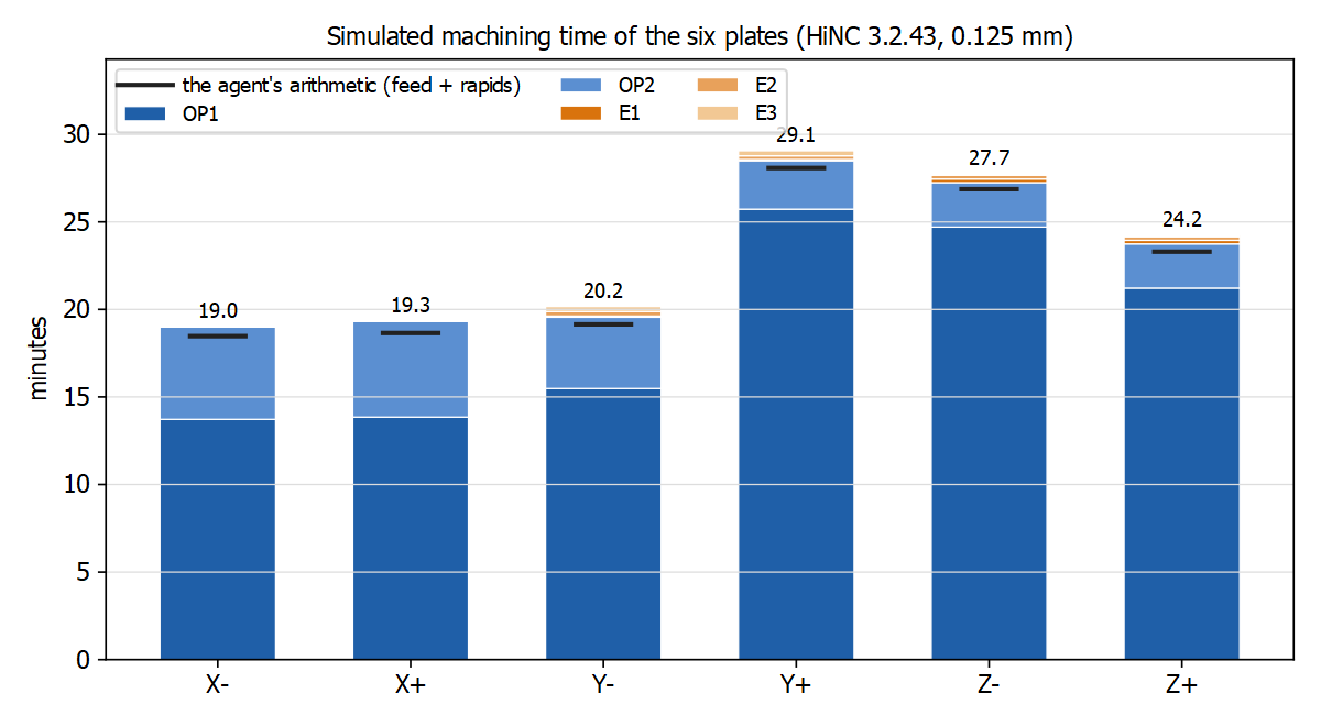
Per plate: HiNC's simulated time against the agent's arithmetic (feed and rapids; tool changes left out), and how long the plays took on the shared server:
| Plate | Clampings | Steps | HiNC (min) | Agent's arithmetic (min) | Play, wall clock (min) |
|---|---|---|---|---|---|
| X- | 2 | 372,067 | 19.0 | 18.5 | 20.7 |
| X+ | 2 | 372,679 | 19.3 | 18.6 | 22.7 |
| Y- | 5 | 400,158 | 20.2 | 19.1 | 20.0 |
| Y+ | 5 | 621,210 | 29.1 | 28.1 | 22.3 |
| Z- | 5 | 560,070 | 27.7 | 26.9 | 31.4 |
| Z+ | 5 | 512,278 | 24.2 | 23.3 | 23.0 |
| Six plates | 24 | 2,838,462 | 139.5 | 134.5 | 140.1 |
The finished parts against the design (D1). HiNC's exported parts, compared with the design meshes by the agent's script; lengths in mm, one cell 0.125 mm.
| Plate | Deepest over-cut | Surface within one cell | Most proud | Where proud by more than a cell | D1 |
|---|---|---|---|---|---|
| X- | 0.019 | 96.5 % | 0.77 | hole-mouth countersinks and chamfers; the foot's chamfer, about 1 × 45° where the list of unprogrammed features says 0.5 × 45° | to be confirmed |
| X+ | 0.026 | 96.7 % | 0.77 | the same | to be confirmed |
| Y- | 0.128 | 97.9 % | 1.51 | the holes' 90° drill points (the agent's drills are 140°), hole mouths | fail (3 µm past a cell) |
| Y+ | 0.159 | 96.7 % | 4.00 | rail-end corners 4.0 / 2.4 mm and 1.8 mm under the rail: stock the plan's residual report named beforehand, out of the chosen cutters' reach | fail |
| Z- | 0.130 | 97.1 % | 1.51 | drill points, hole mouths; round the E1 / E2 seats the export has holes and was not measured (the 120° defect) | fail |
| Z+ | 0.128 | 95.9 % | 4.00 | as Y+ | fail |
The over-cuts beyond a cell are 3–34 µm, along inside edges. A 0.125 mm cube grid can stand off an edge by half a cell's diagonal (0.177 mm), so this is the measuring method's limit, but the criterion says one cell, and the plates are judged as written.
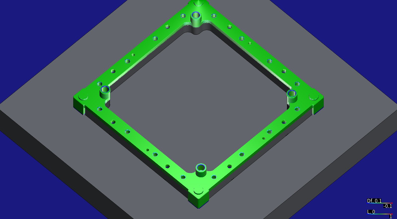
HiNC's canvas: plate X- finished, on OP2's sub-plate, coloured by the deviation from the design (±0.1 mm). Captured on HiNC 3.2.43.
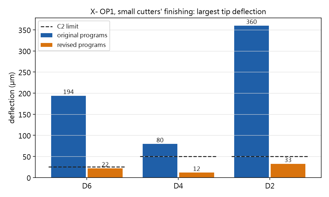
X- OP1's original and revised programs, each replayed whole on HiNC 3.2.45 at 0.125 mm for the NC-optimization study.
Per plate, the accepted programs' largest readings: the tip deflection of each cutter's final passes and of the ball ends in the coves (µm), the roughing's spindle power ratio and the milling cutters' largest stress ratio:
| Plate | D6 walls | D4 corners | D2 corners | Ball ends in the coves | Roughing, power ratio | Milling, stress ratio |
|---|---|---|---|---|---|---|
| X- (OP1 replayed on HiNC 3.2.45) | 21.8 | 11.7 | 32.7 | — | 2.632 at one ramp reversal (every other step at most 0.78) | 0.70 |
| X+ | 19.6 | 14.1 | 34.2 | — | 0.76 | 0.70 |
| Y- | 21.6 | 26.7 | 38.6 | D4 24.5 | 0.77 | 0.66 |
| Y+ | 21.6 | 24.5 | 55.8 at one step (99.9th percentile 37.1; the D2 stage replayed on HiNC 3.2.45) | D4 24.5 | 0.77 | 0.66 |
| Z- | 23.1 (T9, the long D6); 10.7 (T2, in OP2) | 37.6 (T8, the 25 mm neck) | — (semi-finish only) | D4 45.1, D2 48.5 | 0.76 | 0.55 |
| Z+ | 19.0 | 24.5 | 48.5 | D4 24.5 | 0.90 | 0.63 |
| Limit | 25 | 50 | 50 | 50 (set afterwards) | 1 | 0.8; 0.5 for D4 and under |
The revision, change by change. What the agent changed in its CAM after plate X-'s first acceptance, why, and how it knew the change worked; all 24 programs were generated again with it:
| Change | Why | How it was known to work |
|---|---|---|
| Feed scaled to the cutting section: every 0.05–0.5 mm of path, the volume removed from the column of stock within the flute length, over the length; above a reference section the feed drops in proportion, to no less than 30 % when roughing and 5 % when finishing, in steps of 5 % | the power ratio passed 1 only on steps where the D16 met more than 0.55 of its diameter at full depth | X-‘s roughing at most 0.78 on a trimmed play |
| Walls in two passes: a semi-finish leaving 0.1 mm and a final pass taking it; the floor finish keeps the walls’ 0.3 mm | one pass taking 0.3 mm bent the D6 38 µm on a straight wall and the D2 67 µm (99th percentile) | the C2 row above |
| The engagement raster by scanlines (see The engagement raster's own two faults) | the first raster let a hole erase an island, and the D16 cut 0.9 D wide at full feed | on a toy shape no cell differs from a point-in-polygon test |
| Long cutters planned on their own: a D4 with a 25 mm neck, a D2 with a 21 mm neck, a D6 with 26 mm of flute; a clamping is planned again when a tip goes deeper than its cutter reaches (see Deeper walls need longer cutters and a fresh plan) | a short cutter's depths on a long cutter double its deflection; the D6 with 20 mm of flute rubbed a wall with its shank | Z- OP1, planned again with the long D4 and D6, with no collision |
| Coves: their axis heights join the levels; the balls take them in three to six passes at 25–50 % feed (see A strip left over the rail coves) | the ball cut with its whole flute length, at a stress ratio of 1.18 | the D2 ball's deflection 125 → 48.5 µm |
| Ramp legs of at least 0.5 mm, and no near-zero segments: every path drops a point closer than 0.05 mm to the one before and within 2 µm of the line through its neighbours (see Path pieces too short to read) | HiNC read a power ratio of 2.63 and a cutting width of 0.35 mm on steps of 0.034 and 0.002 mm | those steps did not come back |
| Slower round inside arcs, the feed times ρ / (ρ + r); final-pass feed 80 % for the D6 and 60 % for the long D6 (see The long D6 on straight walls and in inside corners) | 18.9 N and 28.7 µm on a straight wall, 32–49 N in corners; at 70 % the long D6 still bent 26.6 µm on one step, and at full feed the D6 bent 25.0–28.0 µm on three steps of X- OP1 | the C2 row above |
| 0.3 mm on the diameter left for the H7 seats' reamer (D5.2, reamed to D5.5) | Z±'s reamer touched nothing, first taken for a 0.2 mm allowance finer than the cell, later traced to the 120° placement; 0.3 mm is still a usual reaming allowance in aluminium, so it stayed | Y±'s reamer touches stock at 0.125 mm |
The revision's price. The planned feed and rapid time of the six plates went from 97.2 to 134.5 minutes (+38 %); HiNC's simulated time for the accepted programs is 139.5 minutes.
What HiNC did that its geometry does not explain. Each item comes with a reproduction or the numbers; the first two are recorded for HiNC's engineers.
| # | Behaviour | Evidence in this case | How the case handled it |
|---|---|---|---|
| 1 | edge set-ups placed 120° about a diagonal: no force, circular milling removes nothing, the reamer touches nothing; the exported part has holes round those features | Z± E1 / E2 and Y± E1: zero force at every drilling and milling step, zero removal rate on the circular milling; the same plates placed 90° or 180° read normally; 9,565 open edges in the export | stated as is: those loads are not readings, four reaming passes fail A, D1 does not see those features; the programs keep them |
| 2 | drill stress ratios change with the placement, and like holes read unlike | the same D1.6 at the same 22.4 N: 1.137 placed 90°, 0.304 placed 180°; Y- E3's D2.5 at 112.7 N and 3.80 (the same drill in OP1: 34.5 N, 0.197); in X+ OP1 three of four like D1.0 corner holes 1.674, one 0.195 | listed under C1 with these comparisons |
| 3 | the step at a ramp reversal reads six times the removal rate of its neighbours | X- OP1 roughing: 1,090 → 6,031 → 283 mm³/s, power ratio 2.632 (every other step at most 0.78) | listed under C5 |
| 4 | a near-zero step reads 0.2–0.35 mm of cutting width | final-pass deflection 34–52 µm on 0.0014–0.0028 mm segments, ≤ 21 µm on the 0.1 mm steps beside them | the CAM drops collinear points closer than 0.05 mm |
| 5 | a drill's rapid out of its own hole, or down to the R plane, reports a 0 mm³ Play-RapidCut |
Z± E1 / E2 and Y± E1: 0 or 5·10⁻¹⁷ mm³ removed | classed as grazing contact (under 0.001 mm³, a class set afterwards); HiNC's threshold left alone |
For a machining engineer. Before any aluminium was cut, the numbers give:
- Stick-outs that clear, from a height map grown by each holder's radius, confirmed by HiNC's holder check in 24 clampings and by a negative control that hit where the map said.
- What would have gone wrong on the machine: a D16 roughing past the spindle's rating wherever it met more than 0.55 of its diameter at full depth (99th percentile 1.61); floor passes that took a wall's whole allowance; small cutters bending 194–360 µm on finishing passes; a D6 shank rubbing Z-'s walls and a D2 ball's shank cutting into Z-'s tab; a rapid grazing the stock at a ramp's start; a length offset left active through a tool change.
- The time: 6.3 hours for a set of six plates, of which 139.5 minutes are programs; the side panels take longest (20–29 minutes each, against about 19 for an X plate).
- What the chosen cutters cannot make: 4 mm of stock at the rail ends of Y+ and Z+, which needs a finer or longer cutter, or a four- or five-axis set-up.
For a teacher or student, the case is a complete multi-clamping plan for thin aerospace plates: counting clampings from the holes' axes, using the drawing's M3 holes to hold the part in OP2, nests under 1.6 mm sheets, an end-cutting reamer for flat-bottomed H7 bores, a feed scaled to the stock the cutter meets, walls finished in two passes, and a negative control that proves the holder check runs.
For someone weighing the approach: an agent with no CAM program to start from wrote one, and HiNC's per-step loads, contact counts and exported parts steered its revisions of all 24 programs, round by round, against criteria fixed before the first play. The acceptance ran from 08:15 to 21:38 on one day on the shared server, one plate at a time, with two pauses for other cases' acceptance; the record does not give the memory it used.
Honest limits
- All simulation, no cut. HiNC's forces, power and deflection come from its library's AA7075 data; that data set was already flagged in another case as an outlier among aluminium alloys, and here it gives about 2.2 J/mm³. The revision was tuned against HiNC's readings; if the data read high, the revised programs are conservative on a real machine.
- Deflection is the tip's largest per turn, not the wall's form error. On a straight wall in climb milling the deflection at the point that generates the surface is usually smaller; C2 uses the largest, the cautious reading.
- HiNC does not model the workpiece's elasticity. The 1.6 mm sheets and 1.1 mm boss walls were judged by putting HiNC's forces into the agent's strip and cantilever-tube models (C3, C4).
- Features not programmed: the 0.1 × 45° and 0.5 × 45° chamfers, the X plates' foot chamfer of about 1 × 45°, the countersinks at the D2.4 holes, the rails' R1 outer rounds, tapping (HiNC has no tap geometry), the design's 90° drill points (the agent's drills are 140°) and the rails' hard anodising. D1 allows stock proud only on these.
- Not simulated: the thin 7075 frame's movement after unclamping and its residual stress, chatter, and tool-change time (the batch adds an assumed 10 minutes per clamping).
- The edge clampings' loads. In Z± E1 / E2 and Y± E1 (placed 120°) HiNC reads zero force; in Y± E2 / E3 the drills' stress ratios change with the placement. Those clampings are judged on shape and collisions only.
- “One cell” as measured. D1 compares HiNC's exported cube-grid surface with the design mesh; on an inside edge the grid can stand off by half a cell's diagonal (0.177 mm), more than one cell. Round the features of the 120° defect the export has holes and was not measured.
- Residual stock. At the rail ends of Y+ and Z+ a slender block 3.8 mm tall stands 4 mm proud, listed beforehand by the plan's residual report as out of reach of the smallest cutter chosen (a D2 with a 16 mm neck).
- The fixtures are the agent's. The vise, the sub-plates and nests and the standing vise clampings are reasonable choices, not the TU Wien team's; the source gives no process.
- No blind build. No second agent rebuilt the case from its record.
What a reader can take to their own case
- Count the clampings from the holes' axes. Merging cylinder faces into holes and grouping them by axis shows every face a part needs before the plan is written.
- Read the drawing's manufacturing notes. Holes “for manufacturing” decide which face comes first; “Stirnreibahle” decides the reamer.
- Check the reference mesh before trusting it. A mesh that is not closed, or whose volume is not the part's, turns every comparison into noise.
- Size the stick-out from the part, and prove the check runs. Grow a height map of the part by the holder's radius at several heights, and play one cutter deliberately short to see the collision appear where the map says.
- Scale the feed by the stock the cutter meets over its whole flute length, not by the layer it cuts: a floor pass can take a wall's allowance over the wall's whole height.
- Finish walls in two passes and slow round inside arcs. A semi-finish leaving 0.1 mm and a feed of ρ / (ρ + r) round inside corners keep a small cutter's load what the straight wall's is.
- Plan long cutters on their own. A long cutter with a short cutter's depths bends far more; plan the clamping again for it.
- Clean the path of near-zero pieces. Ramp legs under 0.5 mm and segments of a few microns read as load spikes in the simulator and do nothing on the machine.
- Count the contact of every operation. A play that finishes is not a play that cut.
- Compare like placements when a reading is zero. Edge set-ups placed differently that read differently point to the simulator, not the program.
- Put the controller's cycle parameters into the time arithmetic. A G83 clearance of 5 mm made small holes' drilling take up to 2.7 times the arithmetic.
Source and licence
- Source: Tim Munhowen (TU Wien Space Team, Vienna), SpaceTeamSat1 Mechanical Design, Zenodo,
version 1.0, published 2025-05-21, doi:10.5281/zenodo.15482346.
The case uses the file
Sts1MechanicalDesign_1.0.zip(2,533,985 bytes): the assemblyCS_STS1.STEP, the six plates' STEP files and the 13-sheet drawing setCS_STS1.pdf. Search terms if the link moves:SpaceTeamSat1 Mechanical Design,zenodo 15482346,CS_Xminus.STEP. - Licence: CC BY 4.0, as the Zenodo record states (read 2026-09-30). The licence gives the material as is, without warranty. The drawings carry the watermark "SOLIDWORKS Educational Product. For Instructional Use Only.", which concerns the author's software licence rather than the data's; this page still shows only the agent's own renders and charts and HiNC's canvas.
- Attribution: “SpaceTeamSat1 mechanical design by Tim Munhowen, TU Wien Space Team (Zenodo, doi:10.5281/zenodo.15482346), CC BY 4.0. Machining set-up by Tech Coordinate's agent.”
- Changed from the original: the part geometry is used unchanged; the stock, the operations and clampings, the fixtures, the tools and holders, the programs and the machine are the agent's.
See Also
- SpaceTeamSat1 CubeSat Structure, Optimized — HiNC's feed optimization on this case: the original X- OP1 program brought to the spindle target and the deflection limits for 3.8 % more time, and 9.9 % off the hand-tuned one
- Showcase — the other cases and how a case page reads
- Replay Acceptance over the HTTP API — watching a play and accepting on evidence
- Cutter Geometry — holder profile, neck and stick-out