RPTU single-setup 3-axis milling benchmark
- Original source
- M. Schmitz, J. Mertes, F. Schillinger, M. Wagner, Benchmark Dataset of 10 Multi-Feature Models for Single-Setup 3-Axis Milling, Zenodo, 2025 — zenodo.org/records/17035762, DOI 10.5281/zenodo.17035762
- Search keywords
Benchmark Dataset of 10 Multi-Feature Models for Single-Setup 3-Axis Milling,zenodo 17035762- Licence
- Creative Commons Attribution 4.0 International (CC BY 4.0)
- Attribution
- Model, NC program and rendering: M. Schmitz, J. Mertes, F. Schillinger, M. Wagner, "Benchmark Dataset of 10 Multi-Feature Models for Single-Setup 3-Axis Milling", https://doi.org/10.5281/zenodo.17035762, licensed CC BY 4.0, provided without warranty. The model and the NC program are unchanged; the simulation set-up (stock, placement, machine, spindle, tool geometry, holder, material) was derived or chosen by Tech Coordinate, as the story below describes. No endorsement of Tech Coordinate, HiNC or this case by the authors is implied.
- About the set
- Ten parts of rising difficulty. The record says each one is machined from an
80 × 80 × 50 mm block with one end mill no larger than 6 mm, without re-clamping, and gives a STEP
model, an NC program and a rendering per part. The programs use one Ø6 flat end mill and German
operation names; their
.ngcextension,G64 P QandG91.1point to a LinuxCNC post-processor (our inference; the record does not say so).
The story of parts 1–3
An AI agent was given the record's STEP model, NC program and picture for parts 1–3, and HiNC running as a web service, to be driven only through its web API and its public documentation. Missing: the stock the programs were written for, where the model sits relative to program zero, the machine, the spindle, the holder, the material, and any tool geometry beyond the comment "D=6, CR=0". The agent built each project, wrote down what counts as a pass before the first play, played each part at a coarse 1 mm resolution to check the set-up and at 0.25 mm to accept it, then wrote its procedure into a build guide and had four independent agents rebuild parts from the guide alone.
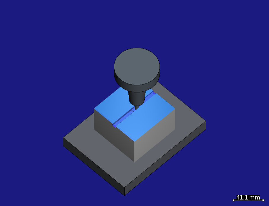
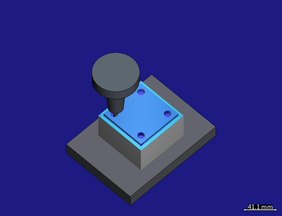
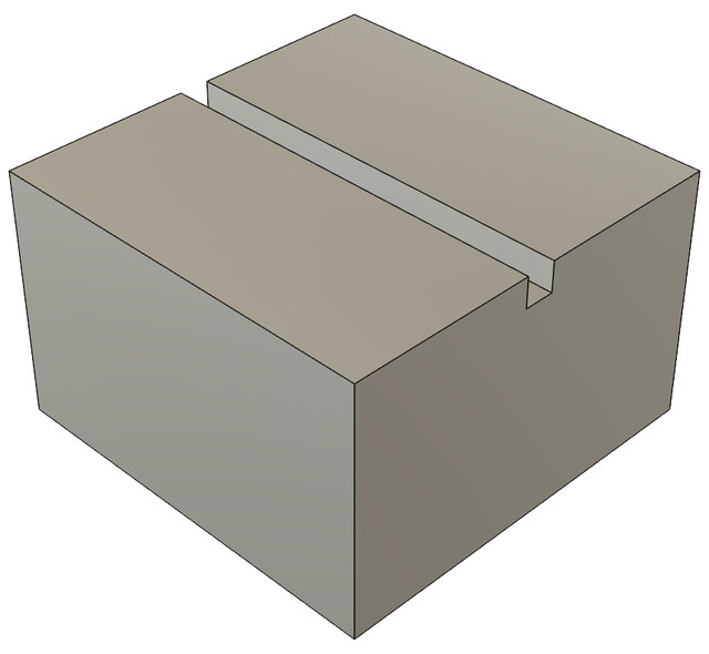
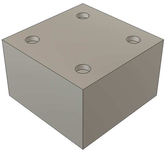
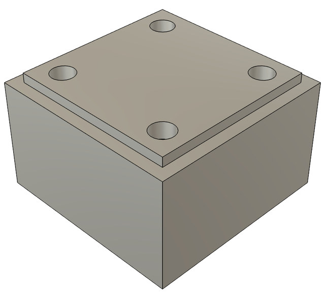
The first two pictures are rendered by HiNC from the CC BY 4.0 models and programs of M. Schmitz, J. Mertes, F. Schillinger and M. Wagner; the three below them are the data set's own renderings of the parts (CC BY 4.0), cropped.
Four of its fourteen dilemmas
Program zero is not given
The models are centred on the origin; the programs use another zero. The agent recovered it from the tool paths' side features, the slot's centre line and the hole helices, not from the floors alone: the model moves by (40.5, 40.5, −53). A peer agent that went by floors alone had found 40, an error only side features show.
The stated block is 1 mm short
The record says 80 × 80 × 50 mm, but the programs face 1 mm off the top of a 50 mm part, so they need a 51 mm block. With the stated one, every comparison with the design would have shown a 1 mm layer of missing material that no program could cut. The agent used 80 × 80 × 51 mm and wrote down why.
"Finished" is not "passed"
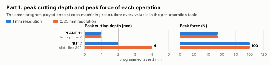
HiNC's "Finished" says only that the run reached its end; a program that never mounts a tool finishes too, without cutting anything. So the agent accepted a run on seven kinds of evidence instead: more than zero steps, the tool touching material, every line executed, the simulated time, a comparison with the design built, no message outside the expected list, and a depth peak equal to the part's reference value, such as part 1's programmed 2 mm layer. All three parts passed every item at both resolutions.
The depth peak doubles at the finer resolution
Part 1's peak cutting depth reads 2 mm at 1 mm resolution, its programmed layer, but 4 mm at 0.25 mm. Taken for a datum error, the jump could have got a correct placement "fixed". The agent listed the depth step by step and traced every 4 mm step to one block of the slot's Z−5 layer: the slot is exactly one tool diameter wide, so at the finer resolution its flank rubs material the layer above left on the wall. The datum check uses the coarse run, and the force peak, about 100 N, is the same at both.
The other ten are in the full record, among them programs in a dialect no HiNC controller brand matches, a build guide tested on four agents that saw nothing else, and several agents sharing one server.
The result
All three programs played unchanged, every line executed, and all three passed acceptance at both resolutions: 52,600, 84,637 and 126,971 steps (one per spindle revolution), 177, 297 and 448 s of simulated machining, and peak cutting forces of about 100, 54 and 102 N on the assumed material and tool, the same at both resolutions. HiNC's collision check, which also covers the holder and the shank against the stock, reported no contact. A replay took 15 to 25 s at 1 mm and 30 to 65 s at 0.25 mm on a 32-thread server, in an estimated 1.4 to 1.7 GB of memory. All four independent rebuilds reached the same step counts, program zero and messages. Everything is simulated; no part was cut on a real machine.
| Key number | What it is |
|---|---|
| 80 × 80 × 51 mm | the block the programs need; the data set states 80 × 80 × 50 mm, 1 mm short |
| (40.5, 40.5, −53) mm | where the model sits relative to program zero, recovered from the slot's centre line and the hole helices |
| 52,600 · 84,637 · 126,971 | steps of parts 1, 2 and 3, one per spindle revolution, the same at 1 mm and at 0.25 mm; every one of the 320, 514 and 1,333 lines executed |
| 177 · 297 · 448 s | simulated machining time, rapids included, without acceleration |
| about 100 · 54 · 102 N | peak cutting force, on the assumed Al6061-T6 and tool, the same at 1 mm and at 0.25 mm |
| 2 mm → 4 mm | part 1's depth peak at 1 mm and at 0.25 mm: all 204 steps of 4 mm lie in one block, where the full-width slot's flank rubs material the layer above left on the wall; the set-up is right |
| 4 of 4 | rebuilds by independent agents from the written guide alone that matched every reference number |
| 15–25 s · 30–65 s | one replay at 1 mm and at 0.25 mm on a 32-thread server, in an estimated 1.4–1.7 GB |
What it brought
- For a machining engineer: the stock and the program zero the programs really need, known before the first cut, and a plain list of what the simulation assumed.
- For a teacher or a student: a worked example of turning published CAM data into an accepted simulation, with the checks that make it trustworthy.
- For someone deciding whether to use an agent with HiNC: fourteen dilemmas found and resolved, and a procedure other agents followed to the same numbers four times out of four. People set the rules (a realistic holder at a shop's stick-out, public documentation only, one folder per case); the agent did the rest.
Read the full case record: parts 1–3
The story of parts 4–10
A second agent took parts 4–10, with the same kind of files, the same gaps and HiNC as a web service. Their programs run from 2,509 to 71,377 lines. It reused the first agent's build script, changing only the part-specific values, so the ten parts share every other choice. It wrote down what counts as a pass before any run, played each part at 1 mm and then 0.25 mm, and tried the two largest programs on excerpts first. Reviewer agents told to refute its written instructions checked them in two rounds, and a peer agent rebuilt part 10 blind from the shared build guide.
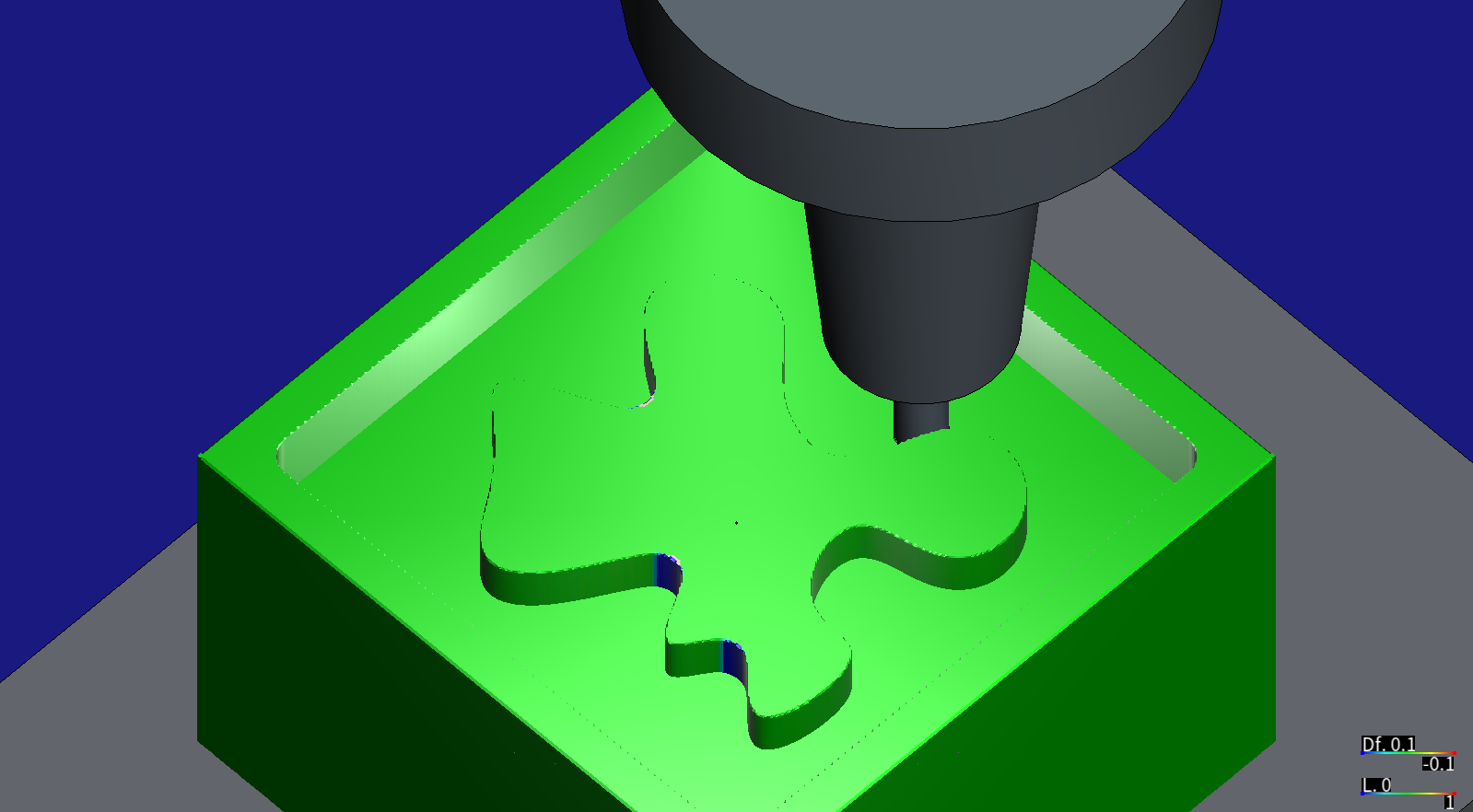
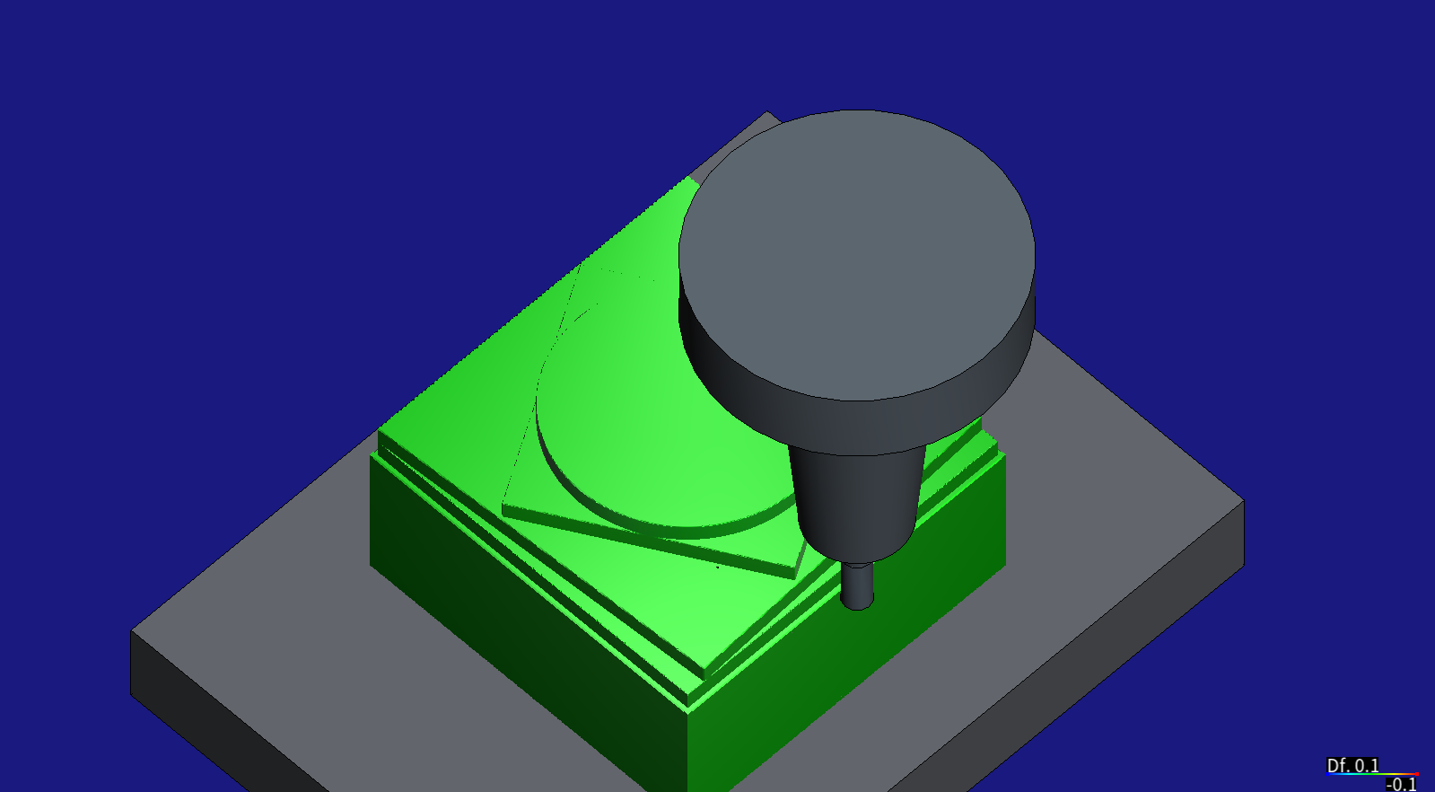
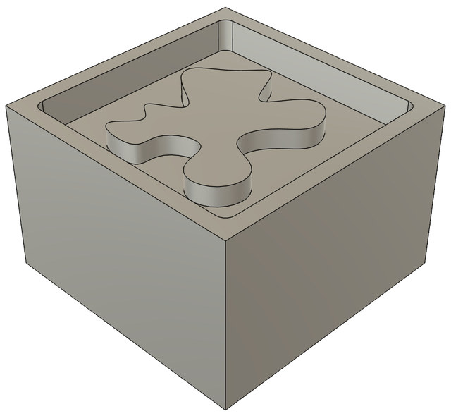
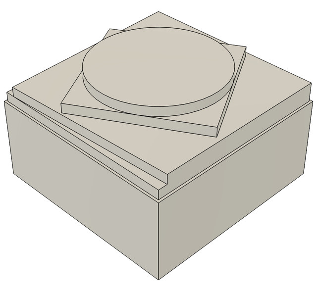
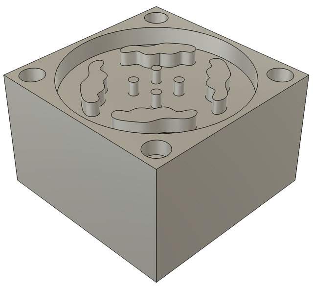
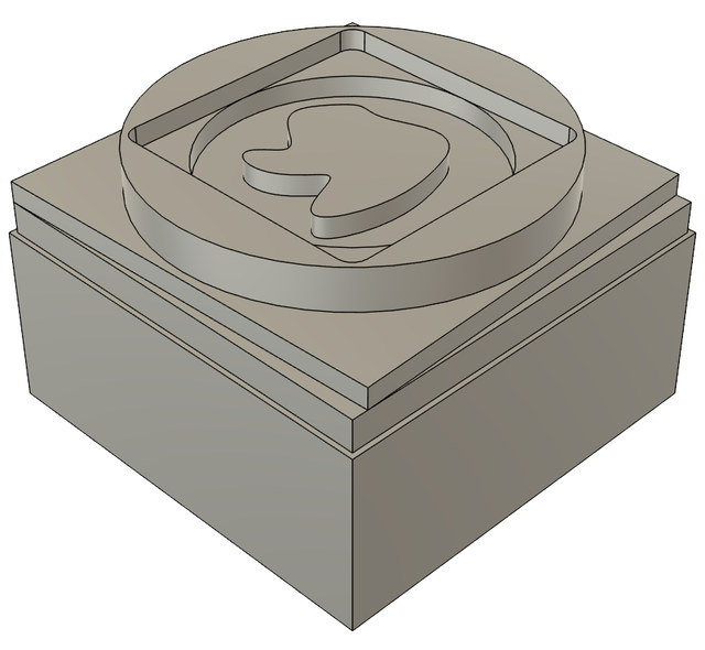
The first two pictures are rendered by HiNC from the CC BY 4.0 models and programs of M. Schmitz, J. Mertes, F. Schillinger and M. Wagner; the four below them are the data set's own renderings of parts 7 to 10 (CC BY 4.0), cropped.
Four of its nineteen dilemmas
Program zero moves from part to part
Part 4 came out at (40.5, 40.5), like parts 1–3, and part 5 looked the same. The agent still derived the zero of every part from its own tool paths: the hole helices, the pocket's finishing circle or the finishing passes along straight walls. Parts 5, 6 and 10 sit at (41, 41), and part 8 at (28.534, 40.962). Reusing part 4's numbers would have put part 5 half a millimetre off. HiNC would have raised no warning, and the comparison would have blamed the program.
A long tool that was not needed
Parts 8 and 10 cut down to Z−17 and Z−19. The agent read those as walls taller than the 13 mm flute and gave both parts a long tool at a 30 mm stick-out; both replays passed. A reviewer agent measured the model: the walls are stepped, and the tallest single wall is 8 and 10 mm. Rebuilt with the standard tool at 25 mm, both parts cut the same, and the holder still clears the stock by 8 and 6 mm.
The comparison gives a picture, not numbers
HiNC colours the machined part against the design, but its web API gives no values to read. To back the claim that part 7's program leaves material at the island's bay tips, the agent exported HiNC's machined workpiece and compared it with the design slice by slice. It found three spots of about 2.0, 1.8 and 0.6 mm² at every height of the island, up to 0.7 mm thick, and no over-cut anywhere.
A finishing pass that takes a whole wall
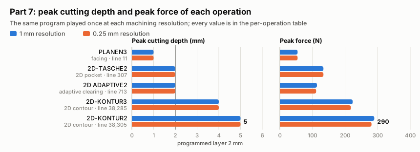
The final contour of parts 7–10 read deeper than any layer: 5, 8, 8 and 10 mm. That looks like a datum error, and it is easy to miss the load it carries. The agent read the peaks operation by operation and checked them against the model and the program. In parts 8 and 10 the final contour is one pass at the bottom, and on the two sides where the step above is flush it meets the whole 8 or 10 mm wall at once; in parts 7 and 9 it is two passes, and the lower one meets 5 and 8 mm of wall. Each peak equals the wall that pass faces, at 1 mm and at 0.25 mm alike. These passes also carry the heaviest load: 290 N on part 7's final contour.
The other fifteen are in the full record. They include a stated block 3 mm short for parts 5, 6, 7 and 10, a message-count check that failed because HiNC folds repeated warnings, and a hole-milling depth reading that looked like a datum error. They also include programs apparently posted for LinuxCNC, which played unchanged on the Fanuc runner, and the written claims the reviewers caught: 76 in the first round and 32 in the second.
The result
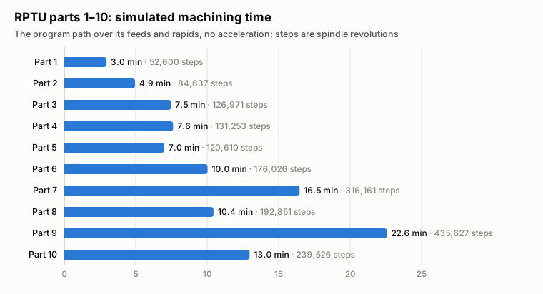
All seven programs played unchanged and executed every line. All fourteen replays passed, seven at 1 mm and seven at 0.25 mm. The parts took 120,610 to 435,627 steps and 7 to 22.6 minutes of simulated machining. On the assumed material and tool, the clearing passes peaked at about 84 to 138 N and the wall-finishing contours at up to 290 N. HiNC's collision check, which also covers the holder and the shank against the stock, reported no contact in any replay. A replay took 25 to 85 s at 1 mm and 60 to 165 s at 0.25 mm on a 32-thread server, and the fourteen replays took about 17 minutes in all. The blind rebuild of part 10 matched the reference steps, executed lines, depths, simulated time, program zero and tool length. Everything is simulated. The data set's authors machined the parts, but none of their results is used here.
| Key number | What it is |
|---|---|
| 14 of 14 | replays passed, seven at 1 mm and seven at 0.25 mm, every NC line executed |
| (40.5, 40.5) · (41, 41) · (28.534, 40.962) | where program zero puts the model in X and Y: parts 4, 7 and 9 · parts 5, 6 and 10 · part 8, each read from that part's own tool paths |
| 120,610–435,627 | steps per part; part 9's 71,377-line program, the largest, takes 22.6 min of simulated machining |
| 2.0 · 1.8 · 0.6 mm² | material part 7's program leaves at the island's three bay tips, up to 0.7 mm thick, measured on HiNC's exported workpiece; nothing over-cut |
| 5 · 8 · 8 · 10 mm | depth peaks of the final contours of parts 7–10, each the wall that pass meets in one go; at 0.25 mm every clearing reads its layer depth, 2 mm (1.5 mm in part 9) |
| 290 N | the heaviest pass, part 7's final contour; the clearings peak at about 84–138 N |
| 8 and 10 mm | the tallest single walls of parts 8 and 10, inside the standard tool's 13 mm flute, so no long tool is needed |
| 76 · 32 | written claims the two review rounds returned, of 839 and 580 checked |
| about 17 min | server time for the fourteen replays, 25–85 s each at 1 mm and 60–165 s at 0.25 mm on a 32-thread server, in an estimated 1.9–3.5 GB each |
What it brought
- For a machining engineer: part 7's program cannot finish its island. The bays narrow to tips tighter than the tool's radius, so a rest-machining pass with a smaller tool is needed. The heaviest load falls on the wall-finishing contours, which are the passes to split if deflection or finish matters. A 25 mm stick-out reaches the deepest parts, 5 mm less than the obvious choice. Program zero sits 0.5 or 1 mm outside the block's corner, depending on the part.
- For a teacher or a student: a data set's description is a claim, not a measurement. Here the block height, one part's feature list and the word "freeform" all needed checking. A single peak over a whole run misleads until it is read operation by operation.
- For someone deciding whether to use an agent with HiNC: building the cases took about 40 minutes of server time and the fourteen replays about 17 minutes, plus two review rounds of about 40 minutes each, all run by agents. The work caught a zero that moves between parts, a wrongly stated stock, a tool longer than needed, and over a hundred wrong or unclear written claims. People set the rules, gave the agent an account on the server and redirected the work.
Read the full case record: parts 4–10
The ten parts and their original files
| Part | Features | Original files | Backup of the originals |
|---|---|---|---|
| 1 | Slot | 1.step, 1.ngc, 1.png | Showcase-RPTU-3axis-01.zip |
| 2 | Four holes | 2.step, 2.ngc, 2.png | Showcase-RPTU-3axis-02.zip |
| 3 | Four holes, rectangular step | 3.step, 3.ngc, 3.png | Showcase-RPTU-3axis-03.zip |
| 4 | Four holes, circular step | 4.step, 4.ngc, 4.png | Showcase-RPTU-3axis-04.zip |
| 5 | Four holes, semi-circular/semi-rectangular step | 5.step, 5.ngc, 5.png | Showcase-RPTU-3axis-05.zip |
| 6 | Four holes, rectangular step, circular pocket | 6.step, 6.ngc, 6.png | Showcase-RPTU-3axis-06.zip |
| 7 | Square pocket with a spline-outlined island | 7.step, 7.ngc, 7.png | Showcase-RPTU-3axis-07.zip |
| 8 | Stacked steps: disc, square turned 30°, inclined step | 8.step, 8.ngc, 8.png | Showcase-RPTU-3axis-08.zip |
| 9 | Four holes, circular pocket, spline-outlined islands and pins | 9.step, 9.ngc, 9.png | Showcase-RPTU-3axis-09.zip |
| 10 | Stacked steps, square and circular pockets, spline-outlined island | 10.step, 10.ngc, 10.png | Showcase-RPTU-3axis-10.zip |