Antenna-cover injection mould: two inserts derived from the part and milled with the agent's own CAM (3-axis)
- Original source
-
Telecom Infra Project, OpenCellular
(github.com/Telecominfraproject/OpenCellular),
folder
hardware/connect-1/: the STEP model and the drawing of part 227-001264, "SHORTY ANTENNA COVER". - Search keywords
OpenCellular 227-001264 SHORTY ANTENNA COVER- Licence
- The repository's hardware documentation is under
CC BY 4.0 (its README and
LICENSE-HARDWARE). The drawing frames still read "CONFIDENTIAL" and "DRAFT RELEASE", left over from before the release; the repository publishes them under that licence. The pictures below are rendered by HiNC from the mould inserts the agent derived, or drawn by the agent's own scripts. - Attribution
- OpenCellular Connect-1 hardware, Telecom Infra Project, https://github.com/Telecominfraproject/OpenCellular, CC BY 4.0; provided without warranty. Mould design and machining set-up by Tech Coordinate's agent (changes: shrinkage, parting surface, mould inserts, stock, toolpaths).
- About the case
- The moulded polycarbonate cover of the OpenCellular Connect-1 base station, about 219 × 85 × 91 mm, with 582 vent holes in its face, a grid of ribs behind it, four screw bosses up to 78 mm tall and two clip boxes. Its drawing states what the mould must achieve (flash and parting-line mismatch within .004 in, among others) and names the resin, SABIC LEXAN 945U; no mould is published.
The story
An AI agent derived the two mould inserts from the part itself (the shrinkage, the parting surface, which half forms which face) and decided what a mould shop would mill and what it would buy or spark-erode: the 582 vent holes became bought core pins, whose fit holes are drilled, and the deep bosses, gussets and clip boxes are milled down to the rib depth and left to EDM. For a generic three-axis machine and P20 pre-hardened mould steel it chose catalogue tools in shrink-fit chucks, from a Ø10 mm roughing end mill down to a Ø1 mm one in the rib slots, and wrote every toolpath with a CAM script of its own. It wrote its pass criteria down before the first play and drove HiNC through its web API. HiNC has no CAM of its own; it was the check on the agent's paths. A small patch of each insert was played, revised and played again before each whole insert was accepted on one valid play.
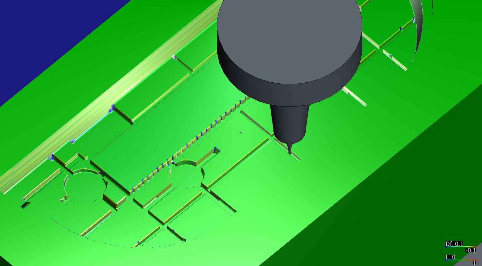
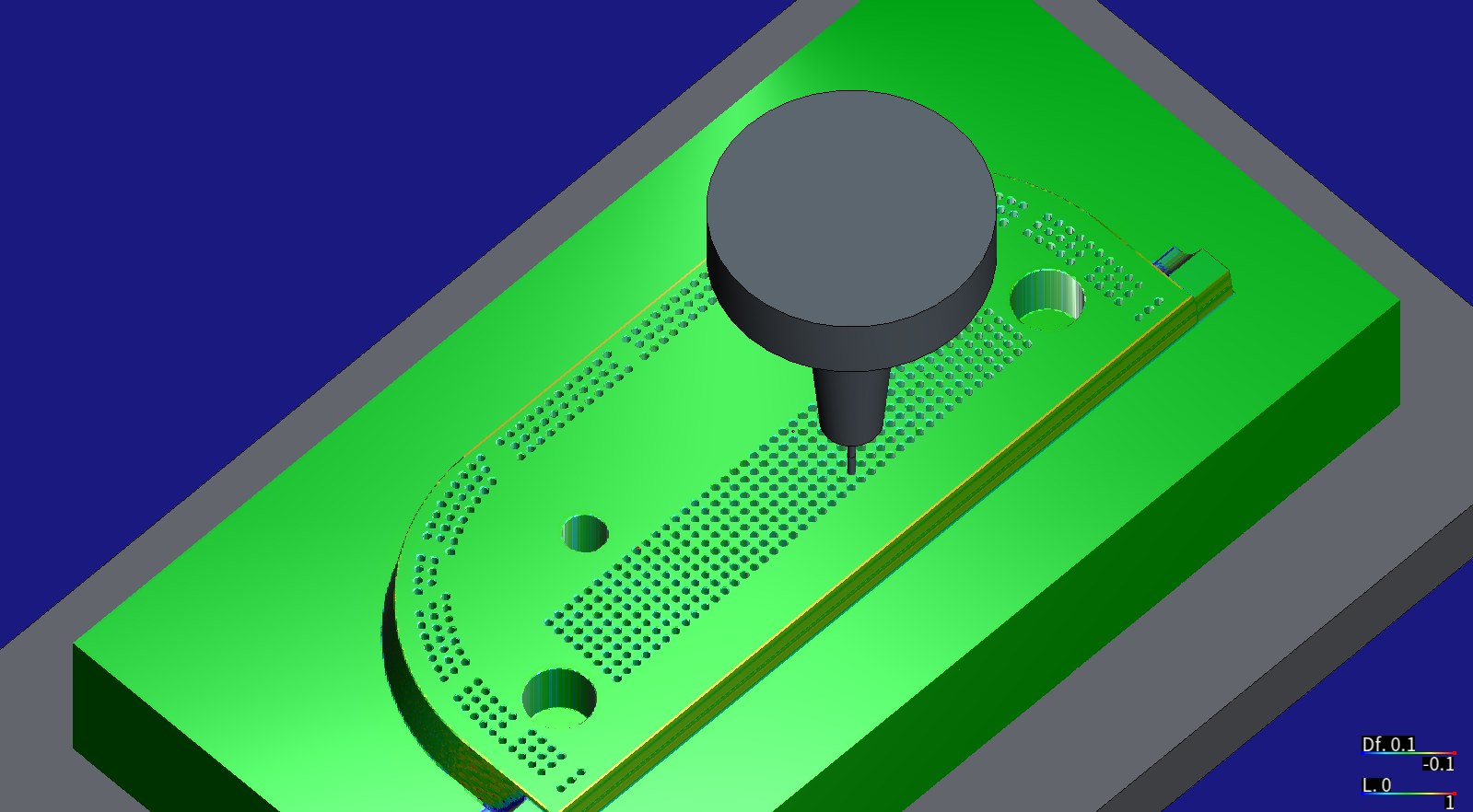
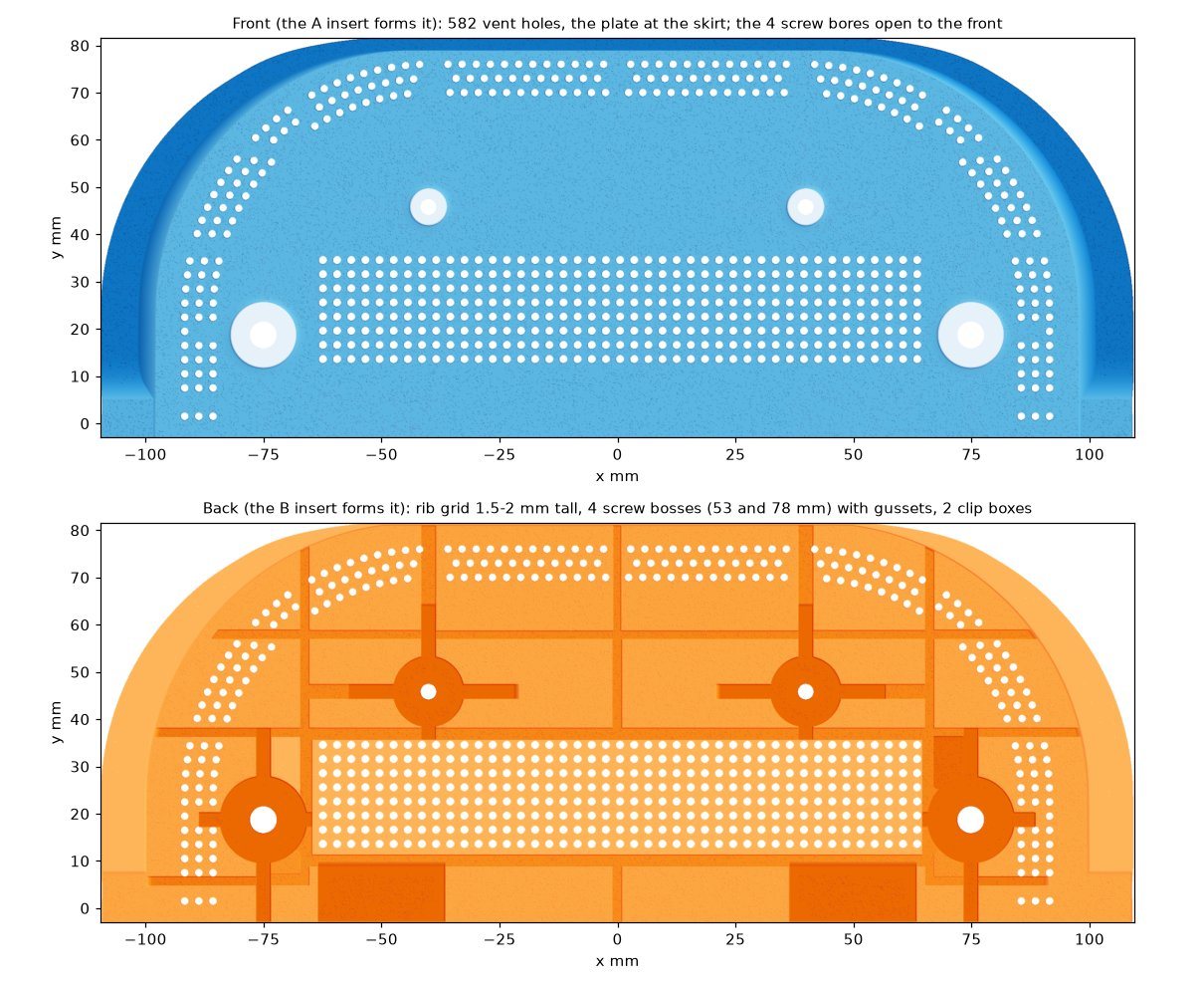
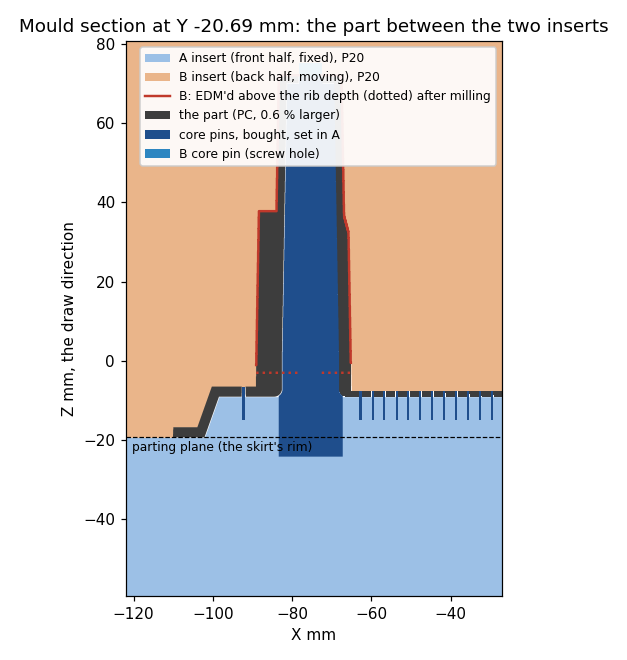
Pictures rendered by HiNC from the mould inserts Tech Coordinate's agent derived from TIP's CC BY 4.0 part model; not TIP's design files. The part, the mould section and the load chart are drawn by the agent's own scripts from that model and from HiNC's readings.
Four of its eleven dilemmas
582 vent holes: pins in which half?
A mould does not mill 582 holes of 1.8 mm; it stands core pins in them. Which half carries the pins follows from their draft, measured at both ends of each hole on the part: at the median the holes narrow from 1.86 mm at the face to 1.81 mm at the back of the 1.5 mm plate and 1.72 mm at the back of the 2.5 mm one. So the pins stand in the front (A) insert and shut off flat on the back (B) one, and the milling program only drills their fit holes, Ø1.8 × 6 mm before reaming. HiNC drilled all 582 to the planned depth.
A false step made by the agent's own code
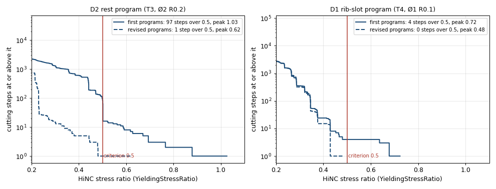
On a trimmed patch HiNC read a stress ratio of 0.72 on the 1 mm tool at the top of the skirt's outer wall, a face drafted only 2.5°, and flagged its neck against the workpiece. An agent traced the tool's path there to errors of up to 2.4 mm in the design heights, on a face that is smooth in the part, and to the agent's own rasteriser, which skipped cells of thin steep triangles; a second agent confirmed it with its own code. The comparison with the design could not see the step, since both came from the same height field; the load reading did. With the rasteriser fixed and the mould and its programs derived again, the tool's peak fell to 0.48 and HiNC flagged its neck nowhere.
Which half forms the skirt?
A mould opens one way, and every face must draft away from the half that forms it. The cover's skirt runs round three sides, and its outer face could belong to either half. Measured on the part, its outline shrinks from 219.00 mm at the rim to 218.16 mm at the plate: a draft towards the back. So the back half forms the skirt and the parting plane is its rim; where the plate runs past the skirt, the front half's plug reaches the plate and a 5° shut-off runs down to the parting plane.
A micro tool that would have taken twelve hours on a small patch
The rib slots' ends by the skirt wall are out of reach of the 1 mm tool's 4 mm neck: its 4 mm shank meets the top of the wall. A long-neck 1 mm tool with a 16 mm neck reaches them, but for a neck 16 times its diameter the maker's slotting conditions are 0.005 mm per pass at 125 mm/min. The agent's CAM planned it on the trimmed patch alone: 3,261 levels and 718 minutes, for less than 0.05 cm³ of steel. A rule written before any play said that if this tool needed more than 60 minutes on the whole insert, its slot ends would go to the EDM electrodes that already make the gussets. It needed twelve times that on the patch alone, so it was dropped before HiNC played anything. At acceptance, the stock HiNC left at those slot ends, up to 2.2 mm, was all stock the agent's model also left for EDM.
The other seven are in the full record, among them the small tool meeting corners head-on, which the program now slows into, a setting that made every step 35 times slower, a feed the agent's NC writer dropped, and the cutter HiNC models as a 24-sided prism.
The result
At acceptance HiNC played each whole insert, one program per run: the B insert's five programs in 3.40 million steps, on its second play (the first was stopped part-way and played again with every rapid rewritten to descend vertically), and the A insert's six in 1.22 million. Every program's time came within 0.10 % of the agent's own estimate on the B insert and 0.36 % on the A insert. The B insert takes 12.0 hours, 42 % of it the 1 mm tool in the rib slots and 25 % the 2 mm tool; the A insert takes 3.9 hours, 7 % of it drilling the 582 pin holes; the pair, 15.9 hours of milling and drilling before EDM. The agent compared the stock HiNC exported with the design column by column on a 0.05 mm grid, over the flat and gently sloped faces. On the B insert the floors sit at a median of +0.002 mm and the parting face, which no program touches, at 0.000 but for a line one cell wide along its rim that reads down to −0.077 mm; on the A insert the parting face sits at +0.006 mm and the plug's face at a median of +0.005. Everything left more than one mesh width (0.0625 mm) proud (70.5 mm² on B, 51.8 mm² on A) is stock the agent's own model also leaves, among it the EDM regions, the rib-slot ends at the skirt wall, small fillets at the foot of walls and two corners of the plug. Cut below the design by more than one mesh width: 8.1 mm² on B, mostly lines one cell wide along wall edges; by more than one finishing cell (0.125 mm), 0.1 mm² on each insert in single cells, the deepest −0.187 mm on B and −0.365 mm on A. All 582 pin holes were drilled to depth, each at 116.8 N and a stress ratio of 0.24; on the B insert the spindle peaked at 0.56 of its rating, in roughing.
Of the criteria written before the first play, the time (C4 (a)) was met on both inserts, and the holder clearance (C1) and the rest tools' loads (C2 (b)) on the A insert. The parting faces (C6) were met but for that line on the B insert's rim, deeper than one mesh width; the 5° shut-off is judged by HiNC's picture only. The rule that dropped the long-neck tool (C4 (b)) was applied before the first play, and the time shares (C4 (c)) are reported, not judged. The rest were not met as written, or only in part. HiNC's cutting depth is the height of the tool's contact, not the chip, so the depth half of C2 (a) fails on both, and the cells cut below the design by more than one mesh width fail the no-gouge half of C2 (c) on both. On the B insert 8 steps of the 2 mm tool and 32 of the 1 mm tool read a stress ratio of 0.5 or more; four of them read over 1, all at a row of 1 mm teeth on the plateau's side, three of them the 1 mm tool's, whose program has no corner slowdown. Over the whole 1 mm program, mostly in the rib slots, the tool's tip deflection reached 19.5 µm at the 99th percentile and 78.5 µm at its peak, at that row of teeth (the program replayed for its NC optimization), against the 10 µm C3 allows in the rib slots. HiNC flagged the 1 mm tool against the stock 48 times and the 2 mm tool 3 times, all as collisions of the tool's shank: at each of the 1 mm tool's 48 its neck clears the design's walls by 0.025 mm, exactly its relief under the flute, and HiNC's own stock by 0.005–0.075 mm. Five rapids on the B insert touched the stock for no measurable volume. On the A insert, at 17 of the 582 holes the drill's rapid retract took a ring off the wall in HiNC and read up to 5,460 N; a real drill does not cut that ring on its way out. The acceptance plays took 1 h 54 min and 49 min on a shared 32-thread server, with memory peaks of 30.9 and 43.6 GB, the second with about 25 GB carried over from earlier work. Everything is simulated; no mould was made.
| Key number | What it is |
|---|---|
| 15.9 h | milling and drilling of the pair of inserts before EDM: 12.0 h on the B insert, more than half of it the 2 mm and 1 mm rest tools, and 3.9 h on the A insert |
| within 0.4 % | HiNC's simulated time against the agent's own estimate, for every one of the eleven programs |
| +0.002 mm | the B insert's floors against the design, at the median (+0.005 mm at the 99th percentile); the A insert's parting face +0.006 mm, its plug's face +0.005 mm |
| 70.5 and 51.8 mm² | left more than 0.0625 mm above the design on the B and the A insert, all of it stock the agent's own plan also leaves |
| 582 | pin holes drilled to depth in the A insert, each at 116.8 N and a stress ratio of 0.24 |
| 97 → 1 | the 2 mm tool's steps at a stress ratio over 0.5 on the trimmed patch, before and after its program was revised |
| 1 h 54 min and 49 min | the acceptance plays of the B insert (3.40 million steps) and the A insert (1.22 million) on a shared 32-thread server |
NC optimization of this case →
What it brought
- For a machining engineer: before any steel is cut, HiNC shows that the agent's programs do what they claim: every program within 0.4 % of its estimate, the stock after each program as the agent's model expected (but for 26 mm² of slivers the B roughing left, which the semi-finishing took), the finished faces on the design at a median of a few microns, and everything left where the plan said no cutter reaches. It also shows where the small tools are worked hardest (the row of teeth on the plateau's side, the rib-slot ends by the skirt wall) and that the 1 mm tool's neck runs 0.025 mm from the walls its own flute cut, which on a real machine is all the margin a deflecting tool has. More than half of the B insert's twelve hours goes to the two small rest tools, a number to weigh against an extra EDM electrode. Not tried here: giving the 1 mm program the 2 mm program's corner slowdown at that row of teeth.
- For a teacher or a student: how an injection-mould insert is derived from the moulded part: the draft decides which half forms each face and where the pins stand. Why a mould shop leaves deep bosses and thin gussets to EDM; how rest machining with small tools follows the stock the larger ones left; and how a simulation's readings (a cutting depth that is the height of contact, not the chip) have to be read before they are judged.
- For someone deciding whether to use an agent with HiNC: from a published part to two inserts played through acceptance, several criteria not met as written (above), the agent derived the mould, wrote its own CAM, set the criteria before the first play and checked HiNC's stock against its own model after every program. HiNC caught three mistakes in the agent's own code (a rasteriser that bent the mould, a writer that dropped feeds, rapids that descended while they moved), and the agent's checks of the stock after every program caught a run that ended "Finished" with nothing cut. The acceptance plays took under three hours on a shared server, and 31 and 44 GB of memory at their peaks, the second with about 25 GB carried over from earlier work. No second agent rebuilt the case.
Read the full case record: antenna-cover injection mould
The source and its backup
| Case | Original files | Backup of the originals |
|---|---|---|
| Antenna-cover injection mould | the Connect-1 hardware folder (GitHub) | Showcase-OpenCellular-InjectionMold.zip |
The zip holds, under Source/, the cover's STEP model and drawing with
the repository's README and hardware licence, as the repository published them; the case's
SOURCE.md; and, under Setup/, the agent's scripts that derive the mould and
write the programs, and the numbers file, with every value marked read, derived, chosen or measured, the
pass criteria written before the first play and the acceptance results. The light pipe beside the cover
in the repository is not used in this case; its two files stay at the source. The meshes and the
programs stay out: the scripts rebuild them.