OpenCellular Antenna Cover: Two Injection-Mould Inserts Derived from the Part and Milled with the Agent's Own CAM
The antenna cover of the OpenCellular Connect-1 base station is a polycarbonate shell about 219 × 85 × 91 mm: 582 vent holes in its face, a grid of ribs behind it, four screw bosses standing up to 78 mm tall and two clip boxes. Its maker published the part as a STEP model and a drawing whose notes state what the mould must achieve, but no mould. An AI agent derived the two mould inserts from the part — shrinkage, parting surface, the fixed and the moving half — decided what a shop would mill and what it would buy or spark-erode, wrote every toolpath with a CAM of its own, and played them in HiNC through the web API. HiNC has no CAM of its own: every path on this page is the agent's, and HiNC was the check on it. The check caught a mistake in the agent's own derivation of the mould, pointed at the corners where the small tools meet their previous level head-on, and turned up a defect in HiNC that ends a run “Finished” with nothing cut.
Everything here is simulated: no mould was made. The built project was the agent's working material and is not distributed.
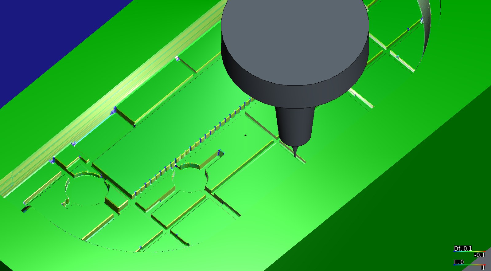
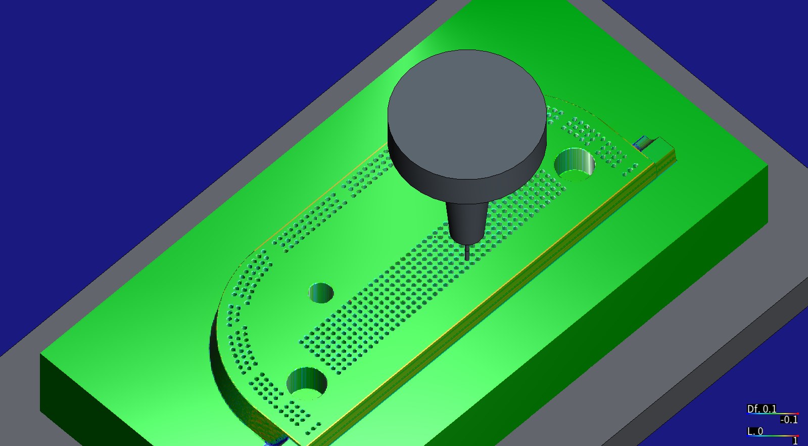
The whole B insert after its last program, coloured by HiNC's geometry difference (±0.1 mm; green is on the design), with the NS TOOL MHR230R Ø1 R0.1 end mill 18 mm out of a generic 4.5° shrink-fit chuck down in a rib slot. The long rectangle is a plateau 1 mm above the floor around it; the round openings are the bosses, left for EDM. Captured on HiNC 3.2.43.
The case
Telecom Infra Project publishes the Connect-1 hardware under CC BY 4.0. For part 227-001264 (“SHORTY ANTENNA COVER”) it gives:
- the STEP model of the moulded part;
- a two-sheet drawing whose notes state the moulding requirements: “FLASH AND PARTING LINE MISMATCH NOT TO EXCEED .004 INCH”, “MOLD DESIGN TO MINIMIZE EJECTOR PIN MARKS, GATE BLUSH, FLOW LINES, AND WELD MARKS”, “GATE TO BE TRIMMED TO WITHIN .004 INCH OF FLUSH”, the resin (SABIC LEXAN 945U, UL94 V-0, UV stabilised) and the finish (“MT-11000 ALL SURFACES”).
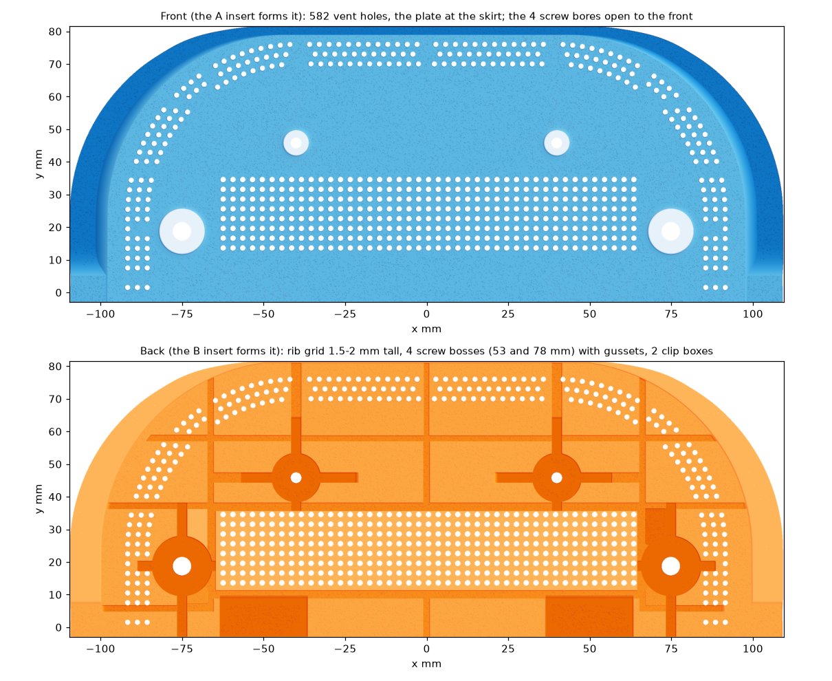
The part as its STEP model gives it, rasterised and shaded by height. Top, the front, which the A insert forms: the 582 vent holes, the four screw bores that open on the face and the skirt round the arc. Bottom, the back, which the B insert forms: the rib grid 1.5–2 mm tall, the four screw bosses (53 and 78 mm tall) with their gussets and the two clip boxes.
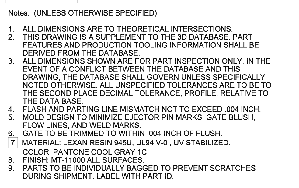
The notes on sheet 1 of the drawing (Telecom Infra Project, OpenCellular, CC BY 4.0; cropped): notes 4, 5, 6 and 8 state what the mould must achieve, note 7 the resin and its colour.
Left out: any mould — the shrinkage, the draw direction and parting surface, which half forms what, the gate and ejectors, the insert steel — and the machine, the tools and the programs.
What the agent built
Everything went through HiNC's web API, following Project Construction, Driving the Web Service over HTTP and Replay Acceptance over the HTTP API. Each value is marked read (stated by the source), derived (computed from it), chosen (by the agent where the source is silent) or measured (in a run on HiNC 3.2.43). The two halves of the mould are called the A insert (the front, fixed half: the cavity side of the cover's face) and the B insert (the back, moving half, which carries the ejectors).
| Item | Value | Basis |
|---|---|---|
| Part | 227-001264, about 219 × 85 × 91 mm; a 1.5–2.5 mm plate, 582 vent holes, a rib grid, four hollow screw bosses (78 and 53 mm tall) with gussets, two clip boxes | Read (STEP) |
| Shrinkage | 0.6 %, uniform | Ranges read from SABIC's LEXAN 945U datasheets (0.6–0.8 % and 0.5–0.7 %); 0.6 % chosen inside both |
| Draw and parting | draw along the bosses; the parting plane at the skirt's rim; a 5° shut-off where the plate runs past the skirt | Parting derived: the skirt's outline shrinks from 219.00 mm at the rim to 218.16 mm at the plate, a draft towards the back; the 5° shut-off chosen |
| A insert | a 10.27 mm plug on a 270 × 140 mm block, 40 mm below the parting face | Plug derived; block chosen |
| Vent holes | 582 core pins standing in the A insert; their fit holes drilled Ø1.8 × 6 mm before reaming (the reaming not simulated) | Pins in A derived from the holes' draft (below); the pre-ream drilling chosen |
| B insert | a pocket 12.8 mm deep with the rib grid as slots 1.6–2.4 mm wide and 1.5–2.1 mm deep | Derived |
| Bosses, gussets, clip boxes | milled to the rib depth; the rest (1,889 mm² of footprint, up to 91.4 mm deep) by sinker EDM | Region derived (every B column above the rib grid's top); EDM chosen: no end mill reaches a boss hole 91 mm deep or a 1.6 mm gusset slot |
| Stock | whole inserts: 270 × 140 mm P20 blocks, B 120 mm deep below its parting face, A 40 mm below it plus the plug with 0.24 mm left on its face; trimmed patches: B 54 × 46 × 30 mm, A 52 × 42 × 25.5 mm | Chosen |
| Design model | each insert as it leaves the milling, meshed from the same 0.05 mm height field the CAM works on: B stopped at the rib depth where the EDM takes over, A with the pins' drilled and the boss pins' milled fit holes | Derived |
| Fixture | a 20 mm ground plate 30 mm past the stock on every side, the insert clamped on it (clamps not modelled) | Chosen |
| Material | P20 (prehardened mould steel) for both inserts, HiNC's shipped P20 cutting data | Chosen |
| Machine | generic three-axis vertical machine, 24 m/min rapids | Chosen |
| Program zero | on the parting face at the block centre; G54 after each reset: whole B (−400, −250, −460), whole A (−400, −250, −540); trimmed B (−315, −271, −550), trimmed A (−314, −227, −565) | Chosen; G54 measured |
| Controller, spindle | Fanuc; the Showcase's generic 24,000 min⁻¹ spindle, 7.5 kW continuous and 10 kW short-term (synthesised, not a vendor's) | Chosen |
| Tools | seven catalogue tools (table below) | Geometry read from the makers' catalogues; conditions read, derived or chosen as the table marks; tool choice chosen |
| Holders | generic 4.5° shrink-fit chucks; each stick-out the longer of what the holder's 1 mm clearance to the stock needs and what the tool's body needs | Chosen; stick-outs derived |
| Programs | one per operation; the agent's own Z-level contour-parallel CAM on a 0.05 mm height field, the stock tracked from each tool to the next, a reach check that limits how low each tool may go by its neck taper, shank and holder | Chosen |
| Mission | before every program its own mesh width — the size of the cells HiNC builds its model of the stock from — and a fixed motion step (below) | Chosen (Mesh Resolution) |
| T | Tool | Used for | Stick-out | Conditions | Catalogue |
|---|---|---|---|---|---|
| 1 | OSG AE-VMS Ø10, 4 flutes | roughing both inserts | 24 mm | side 3,200 min⁻¹ / 900 mm/min, ae 0.2D, slot 2,500 / 550 (read, prehardened steel) | OSG catalogue n_115, pp. 15, 21; EDP 8555900 |
| 2 | NS TOOL MHR230R Ø6 R0.5 × 24 | semi-finishing and finishing | 26 mm | 4,500 / 1,500, ap 0.3, ae 2.1 (read); Z steps 1.0 and 0.15 mm (chosen) | NS TOOL MHR230R size table; conditions F-055 |
| 3 | NS TOOL MHR230R Ø2 R0.2 × 12 | corners and narrow places | 20 mm | 14,000 / 1,500, ap 0.09, ae 0.5 (read); 750 in slots (derived, the catalogue's half feed for slotting); 375 into corners (chosen) | NS TOOL conditions F-054 |
| 4 | NS TOOL MHR230R Ø1 R0.1 × 4 | rest machining, mostly the B insert's rib slots | 18 mm | 25,000 / 1,400, ap 0.055 (read); 24,000 / 1,344 at the spindle's limit, halved for slotting to 672, ap 0.0275 (derived) | NS TOOL conditions F-053 |
| 5 | NS TOOL MHR230R Ø1 R0.1 × 16 | planned for the slot ends, dropped before any play (below) | — | 12,000 / 250, ap 0.01 (read); 125, ap 0.005 for slotting (derived) | NS TOOL conditions F-053 |
| 6 | OSG ADO-MICRO 5D Ø1.8 | the 582 vent-pin holes, G81 |
22 mm | vc 20–40 m/min, 0.03–0.08 mm/rev for alloy steel 28–35 HRC (read); 5,300 min⁻¹ at 30 m/min (derived); 0.05 mm/rev (chosen) | OSG catalogue n_128, pp. 19, 23; EDP 8732032 |
| 7 | OSG AE-VMSS long neck Ø6 × 18 | the boss core-pin holes, helical | 21 mm | 3,710 / 740 side milling (read); 518 as a helix, 70 % of it (chosen) | OSG catalogue n_115, pp. 14, 20; EDP 8556618 |
The mesh widths: 0.25 mm for roughing and semi-finishing, 0.125 mm for finishing and the helical holes, 0.0625 mm for the Ø2 mm tool and the drill, 0.03125 mm for the Ø1 mm tool. The motion steps: 1.0 mm for roughing, 0.4 mm for the finishing and rest tools, 0.3 mm for the helix, 0.1 mm for the drill. Each program plays as its own run from a reset machine, in the resumable layout of A Mission That Resumes: each stage reads the previous stage's stock from a file, plays one program and writes its own.
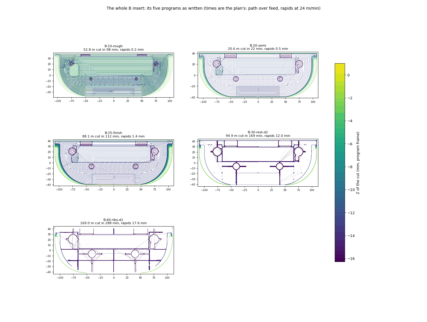
The whole B insert's programs as written: colour is the Z of the cut in the program frame, grey lines are rapids. Each title gives the length cut and the plan's time, the path over its feed with the rapids at 24 m/min, not HiNC's: roughing 52.8 m in 98 min, semi-finishing 20.6 m in 22 min, finishing 88.1 m in 112 min, the Ø2 mm tool 94.9 m in 169 min and the Ø1 mm tool 169.0 m in 288 min, plus 0.2 to 17.6 min of rapids each.
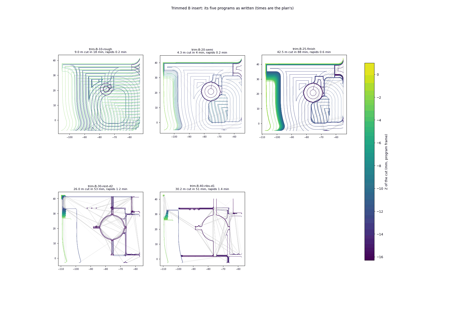
The trimmed B insert's programs as revised, on the patch with a boss, its gussets, rib slots and the skirt wall: colour is the Z of the cut, grey lines are rapids. The titles give the length cut and the plan's time, not HiNC's: roughing 9.0 m in 18 min, semi-finishing 4.3 m in 4 min, finishing 42.5 m in 88 min, the Ø2 mm tool 26.0 m in 53 min and the Ø1 mm tool 30.2 m in 51 min, plus 0.2 to 1.4 min of rapids each.
How the agent managed the work
- Pass criteria before the first play. Seven criteria were committed before HiNC played anything. E, the run's evidence: every program touches the stock and no message beyond progress and one file-lines note per program. C1 the holder and shank clear of the stock (the agent's own check, and no collision in HiNC). C2 the rest tools meeting only the stock their predecessors left — read as HiNC's cutting depth at most the program's step-down plus one mesh width and its cutting width at most the tool's diameter plus one mesh width — their stress ratio under 0.5 at every step, and no gouge beyond one mesh width in the comparison with the design. The stress ratio is HiNC's yielding stress ratio, the largest stress the cutting forces cause in the tool over what its material stands; over 1 for more than one step, HiNC expects the tool to break (Evaluating Process Machinability). C3 the Ø1 mm tools' tip deflection in the rib slots under 10 µm. C4 each program's simulated time within ±10 % of the agent's own estimate, and a rule to drop the long-neck tool if it needs more than an hour on the whole insert. C5 spindle power and torque and the tools' stress within their limits. C6 the parting faces within one mesh width, under the drawing's .004 in. Later readings of a criterion are recorded beside it; no criterion was rewritten.
- Small before large. Each insert has a trimmed twin: a 54 × 46 mm patch of the B insert with a boss, gussets, rib slots and the skirt wall, and a 52 × 42 mm patch of the A insert with a boss pin, 39 vent pins and the plug's edge. The trimmed programs ran first, several times; each whole insert was accepted on one valid play, one at a time on a shared 32-thread server: the B insert's 3.40 million steps in 1 h 54 min, the A insert's 1.22 million in 49 min. The B insert's first acceptance was stopped and played again after the engine defect told below.
- The plan checked against HiNC. After every program HiNC exported the stock it held; a script of the agent's compared it column by column with the stock the CAM believed it had left.
- Adversarial review. The two readings that failed criterion C2 on the trimmed B insert — the Ø2 mm tool's 97 steps over 0.5 and the Ø1 mm tool's loads at the skirt's wall — went to a workflow of seven agents: an analyst per problem who replayed the cut exactly, two refuters per analysis (one rebuilt the geometry with its own code, the other argued that the reading was HiNC's), and one who turned what held into the program revision. Two of the four refuters overturned their analyst in part. A second workflow of 39 agents then checked this page, the case report and the source notes claim by claim against the run data and corrected what did not hold.
- No blind build. No second agent rebuilt the case from its source files and written instructions.
- Sharing one server. Several agents were building product cases on the same server; the heavy plays waited on a shared lock. One of them spotted a setting in this case's build that made HiNC's steps 35 times slower, and another warned that the server's system disk was filling up; this case's step records were on it, so it moved them to the data disk before its long plays.
- Where a person stepped in. HiNC's product owner asked for product cases, moulds among them, rather than paper experiments — this is one of those the agents then collected — and ruled that every tool sits in a realistic holder at the shortest stick-out that is enough.
The criteria as they were written before the first play:
| Criterion | As written |
|---|---|
| E, run evidence | steps > 0; every program touches the stock and executes every one of its lines; no message but progress and success, and one Sys-Init--FileLines per program |
| C1, holder and shank | in the plan, the holder at least 1 mm and the neck taper and shank at least 0.2 mm clear of the stock; HiNC reports no Collided(Workpiece, …) of the holder or the shank and no Collided(Fixture, …) |
| C2, rest material | (a) the rest tools (T3, T4, T5): HiNC's peak cutting depth at most the step-down plus one mesh width and its cutting width at most the tool's diameter plus one mesh width, ramp entries aside; (b) every step of T3–T5 under a stress ratio of 0.5; (c) in the comparison with the design no gouge beyond one mesh width, and stock left only in vertical corners under the smallest tool radius and where the plan says no tool reaches |
| C3, rib-slot deflection | T4's and T5's tip deflection in XY at most 10 µm in the rib slots; a cantilever estimate gives about 1 and 4 µm, and HiNC within three times that passes the beam model's sanity check |
| C4, time | (a) each program's HiNC time within ±10 % of the plan's; (b) if T5 needs more than 60 minutes on the whole B insert, its slot ends go to EDM and T5 is dropped; (c) the share of the time the rib slots and the pin holes take, reported as it is |
| C5, loads | spindle power and torque ratios at most 1 at every step; every tool's stress ratio under 1 |
| C6, parting | in the comparison with the design, the parting face and the 5° shut-off within the acceptance run's mesh width, under the drawing's .004 in |
The dilemmas
Numbers from a play were measured on HiNC 3.2.43; those taken off the STEP or out of the agent's CAM are derived.
Several of the dilemmas below start from the trimmed patches' first programs, each played as its own run on HiNC 3.2.43 before the rasteriser fix and the feed revision told below (the B insert's times to one decimal only). The drill's peaks are the first step of a rapid retract at 2 of the 39 holes, the reading told under Results and benefits:
| Program | Steps | HiNC / plan, min | Stress ratio p50 / p99 / peak | Cutting depth p50 (plan per level), mm | Tip deflection p99 / peak, µm |
|---|---|---|---|---|---|
| B roughing, Ø10 | 24,841 | 18.5 / 18.5 | 0.13 / 0.46 / 0.52 | 1.74 (≤ 4) | 77 / 89 |
| B semi-finishing, Ø6 R0.5 | 25,267 | 4.3 / 4.3 | 0.13 / 0.60 / 0.97 | 0.95 (1.0) | 94 / 165 |
| B finishing, Ø6 R0.5 | 173,884 | 86.7 / 86.8 | 0.02 / 0.10 / 0.57 | 0.44 (0.15) | 16 / 91 |
| B rest, Ø2 R0.2 | 202,736 | 49.4 / 49.5 | 0.11 / 0.44 / 1.03 | 0.25 (0.09) | 101 / 239 |
| B rib slots, Ø1 R0.1 | 196,552 | 52.6 / 52.7 | 0.08 / 0.28 / 0.72 | 0.12 (0.0275) | 19 / 60 |
| A roughing, Ø10 | 4,283 | 1.30 / 1.26 (+3.2 %) | 0.15 / 0.50 / 0.52 | 4.0 (≤ 4) | 86 / 89 |
| A semi-finishing, Ø6 R0.5 | 13,541 | 1.89 / 1.86 (+2.1 %) | 0.13 / 0.60 / 0.60 | 0.85 | 93 / 94 |
| A finishing, Ø6 R0.5 | 91,855 | 43.44 / 43.46 (−0.03 %) | 0.02 / 0.06 / 0.27 | 0.43 (0.15) | 10 / 42 |
| A rest, Ø2 R0.2 | 10,036 | 1.33 / 1.29 (+3.1 %) | 0.09 / 0.29 / 0.36 | 0.18 (0.09) | 66 / 82 |
| A 39 pin holes, Ø1.8 drill | 21,403 | 1.15 / 1.11 (+3.9 %) | 0.24 / 0.24 / 134.6 | 0.45 | 0 / 57,100 |
| A boss pin hole, helical, Ø6 | 13,751 | 4.78 / 4.74 (+0.9 %) | 0.05 / 0.05 / 0.06 | 0.36 | 6 / 6 |
Which half forms the skirt
- Situation. The cover is a shallow shell with a skirt round three sides. A mould opens in one direction; every face must draft away from the half that forms it, and the parting line has to sit where the drawing's .004 in mismatch limit can be held.
- Risk. A parting line put on a face that drafts the wrong way locks the part in the mould, or leaves a visible step on a cosmetic face.
- How it was noticed. Deriving the inserts column by column: every vertical line through the part has a lowest and a highest crossing, and the skirt's outside is the only face that could belong to either half.
- Resolution. The agent measured the skirt's outline on the STEP model at the rim and at the plate: 219.00 mm at the rim, 218.16 mm at the plate, a draft towards the back. The B insert forms it and the parting plane is the rim itself. Where the plate runs past the skirt (the open straight side and the corner tabs) the A insert's plug reaches the plate's front face, and the shut-off from there to the parting plane is drafted 5°.
- Evidence it held. Every column of the part then has its lowest crossing in the A insert and its highest in the B insert, and no column is claimed by both: the A insert's face stands nowhere above the B insert's. Once the rasteriser was fixed (see A false step on the skirt's wall), no column crossed the part an odd number of times.
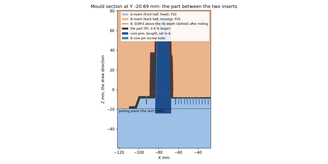
The mould section through an outer boss (derived from the STEP model): the A insert blue, the B insert orange, the part dark grey, the bought core pins dark blue; the B insert is milled down to the dotted rib depth and spark-eroded above it (red).
582 vent holes: pins in which half
- Situation. The face carries 582 round vent holes about 1.8 mm across. The outline the agent wrote when it collected the case said not to pretend to mill them: in a real mould they are core pins or inserts, though it did not say in which half. Which half the pins stand in follows from their draft.
- Risk. Pins standing in the wrong half would have to be pulled through the part on opening.
- How it was noticed. Measuring each hole at both ends of the plate on the STEP model.
- Resolution. The holes narrow away from the face: at the median, 1.86 mm at the face, 1.81 mm at the back of the 1.5 mm plate and 1.72 mm at the back of the 2.5 mm plate (the part's sizes; 1.87, 1.82 and 1.73 mm in the mould with the shrinkage) — the draft of a pin standing on the front half. So the A insert carries 582 bought core pins that shut off flat on the B insert, and the milling program only drills their Ø1.8 × 6 mm fit holes before reaming.
- Evidence it held. The hole count and sizes come from the part itself. On the whole A insert HiNC drilled all 582 to the planned depth (bottoms between Z 3.941 and 3.957 against the plan's 3.938), each at 116.8 N and a stress ratio of 0.24.
The whole A insert after its last program, coloured by HiNC's geometry difference (±0.1 mm): the OSG ADO-MICRO Ø1.8 mm drill, 22 mm out of the same kind of chuck, going into one of the 582 pin holes, with the four boss pins' holes on the plug. Captured on HiNC 3.2.43.

The same drilling on the trimmed A insert, its first programs: the OSG ADO-MICRO Ø1.8 mm drill, 22 mm out of a generic 4.5° shrink-fit chuck, going into the next pin hole with twelve already drilled; to the left, the edge of the plug and the slope of the shut-off. Captured on HiNC 3.2.43.
Screw bosses 78 mm tall
- Situation. Four hollow screw bosses stand 78 and 53 mm tall behind the face, with 1.6 mm gussets, and two clip boxes 25 mm deep with thin walls. In the B insert they are holes up to 91 mm deep and slots 1.6 mm wide.
- Risk. Programming an end mill that does not exist, or one sticking out 90 mm that would break on its first pass.
- How it was noticed. The agent's reach check: for each tool, how low the tip may go before its neck taper, shank or holder comes within its clearance of the stock.
- Resolution. The B insert is milled down to the rib depth there, and the rest — 1,889 mm² of footprint, 91.4 mm deep at most — is left to sinker EDM, as a mould shop would. The bosses' own screw holes are further core pins.
- Evidence it held. The B insert's design model, the one HiNC compares the machined stock with, stops at the rib depth over the EDM regions, so the comparison judges the milled surface only.
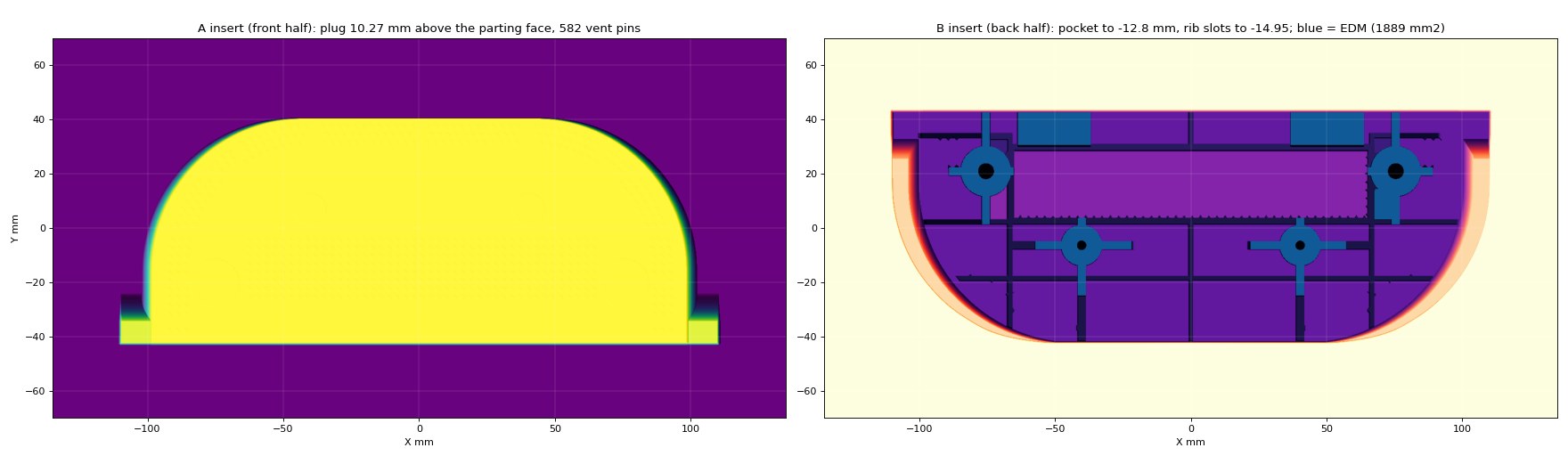
The milling targets derived from the part: the A insert's 10.27 mm plug with its 582 vent pins (left) and the B insert's 12.8 mm pocket with the rib grid, the EDM regions in blue (right).
A micro tool that would have taken twelve hours on a small patch
- Situation. The rib slots' ends next to the skirt wall are out of reach of the 4 mm neck of the Ø1 mm tool (T4): its Ø4 mm shank, 11.7 mm above the tip, meets the wall's top. A long-neck Ø1 mm tool (T5, 16 mm neck) reaches them.
- Risk. Hours of machine time for a few cubic millimetres, or a tool too slender for the conditions it is given.
- How it was noticed. The maker's conditions for an L/D of 16 in slotting are 0.005 mm per pass at 125 mm/min. The agent's CAM planned T5 on the trimmed patch alone: 3,261 levels, 60 m of path, 718 minutes, for less than 0.05 cm³.
- Resolution. A rule written before any play said: if T5 needs more than 60 minutes on the whole insert, its slot ends go to the EDM electrodes that already make the gussets, and T5 is dropped. It needed twelve times that on a patch alone, so T5 was dropped before HiNC played anything.
- Evidence it held. The criterion and its limit are in the case's notes with a commit date before the first play. At acceptance, the stock standing above the design at the rib-slot ends by the skirt wall, up to 2.2 mm, was all stock the agent's model also left there: the slot ends are EDM's, as the rule said.
A setting that made every step 35 times slower
- Situation. By default HiNC takes one step per spindle revolution; the Ø1 mm tool at 24,000 min⁻¹ and 672 mm/min would make 36 steps per millimetre of path and about ten million steps on the whole insert. The agent put a Machining Motion Resolution command set to a fixed step in front of every program, and first gave it a rotary resolution of 1°.
- Risk. A run that crawls and fills the server's memory, on a server other agents share.
- How it was noticed. Another agent building a different product case on the same server saw steps 35 times slower and its process at 25 GB with the same setting, traced it to this case's build script and sent a note.
- Resolution. In the fixed mode the cutter's mesh is built at the linear step and at the smaller of the rotary resolution and 15° per facet, so 1° gave every cutter 360 facets round. On a three-axis machine the rotary value does nothing else; the agent removed it and the mesh went back to 24 facets.
- Evidence it held. The trimmed B insert then played 628,584 steps in 1,762 s at about 4.8 GB.
The cutter is a 24-sided prism
- Situation. The agent's CAM tracks the stock the tools leave on a 0.05 mm height field, so each rest tool only cuts what its predecessors left. To check that model against HiNC, the mission exported HiNC's stock after every program and a script compared it column by column.
- Risk. A model that thinks the stock is gone where HiNC still has it sends the next tool, full length, into material.
- How it was noticed. In the first run that exported the stock after every program, the two agreed after the roughing to a median of 0.002 mm, but HiNC held up to 4 mm more in a few places, 6.2 mm² over 1 mm in all.
- Resolution. With 15° facets HiNC's cutter is a 24-sided prism whose flats sit at R·cos 7.5°, 0.991 of the radius — the Ø10 mm cutter reaches only 4.957 mm. The model had counted cells up to the full radius as cut and missed the slivers the flats leave on slopes. The stock update now keeps a margin of one cell plus R(1 − cos 7.5°).
- Evidence it held. On the revised programs (which also carry the rasteriser fix below) HiNC held more than the model by over 0.1 mm on 7.0 mm² after roughing, 0.4 after semi-finishing, 0.2 after finishing and none after the two rest tools; a few slivers up to 4 mm still stand after roughing, and the semi-finishing tool takes them. Everywhere else the model is the conservative side.
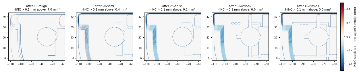
The trimmed B insert on the revised programs, HiNC 3.2.43: the top of the stock HiNC exported after each program minus the agent's model (±0.5 mm). Red is stock HiNC holds and the model does not, which the next tool would meet; blue is stock HiNC has already cut and the model still counts. The area more than 0.1 mm above the model: 7.0, 0.4, 0.2, 0 and 0 mm².
HiNC's cutting depth is the height of contact, not the chip
- Situation. The first trimmed runs used one mesh width, 0.25 mm, for every program, while the finishing and rest tools cut 0.03–0.15 mm per level.
- Risk. Read as the chip, HiNC's cutting depth makes the rest tools look three to six times overloaded, and a program is slowed or a tool dropped for nothing.
- How it was noticed. HiNC's cutting depths had medians three to six times the plan's: 0.32 mm for the Ø2 mm tool against 0.09, 0.155 for the Ø1 mm tool against 0.0275.
- Resolution. The agent first suspected the coarse mesh and gave every program its own width, refining only the faces the fine tools touch. On the regenerated programs the Ø2 mm tool's median depth still read 0.25 mm; the programs had changed too, so even that difference is not all the mesh's. HiNC's cutting depth is the height of the tool's contact with the stock — the slot's side walls included — not the thickness of the chip; another case found the same reading at twice the step-down in narrow slots. So criterion C2's depth half fails as written: the Ø2 mm tool reads a peak of 1.61 mm against 0.15, the Ø1 mm tool 0.80 against 0.06; its width half holds. Whether the rest tools met only what their predecessors left is shown beside it by the stock comparison after each program, and their loads are judged by force and stress ratio, as C2's second half and C5 were written.
- Evidence it held. On straight full-width passes the Ø2 mm tool read a median depth of 0.31 mm for a 0.09 mm level, while the volume HiNC removed per step was 1.02–1.10 times the exact cut and the force 15.2–15.6 N; 9.5 N at 750 mm/min.
A false step on the skirt's wall, made by the agent's own code
- Situation. The agent derives both inserts by casting a vertical line through the part at every 0.05 mm and keeping its lowest and highest crossing. 39,392 of the 6.3 million lines crossed the part an odd number of times; they took the heights of the nearest even line.
- Risk. A mould insert with the wrong shape, and a check that cannot see it: the design model HiNC compares the machined stock with came from the same heights.
- How it was noticed. On the trimmed B insert the Ø1 mm tool read a stress ratio of 0.72 at the top of the skirt's outer wall, a face drafted only 2.5°, and HiNC flagged its neck against the workpiece eight times: four on that stretch of wall, three at the corner of the 5° shut-off beyond it and one during a rapid 1 mm above the stock. One agent traced the tool there to errors of up to 2.4 mm in the design heights on a face that is smooth in the STEP model, and to the rasteriser that made them; a second, casting its own lines, confirmed the odd counts were missed crossings. The rasteriser tested a triangle's cells in an 8 × 8 block when its box held 64 cells or fewer — and a thin steep triangle 2 × 30 cells passes that test by area, its cells past the eighth row never tested.
- Resolution. The block path takes only triangles whose box fits in it; the mould and every program were derived again. The path had been a real overcut — the finishing and rest tools cut up to 0.06 mm (the Ø1 mm tool up to 0.10 mm) into the real wall — but the loads HiNC read on it were high: an exact sweep puts the Ø1 mm tool's radial bite there at 0.009–0.034 mm where HiNC reads 0.05–0.13 mm, and HiNC's removal per step at 2.3–7.4 times the exact volume. None of the eight neck flags is a contact in the exact stock: the four on the wall clear it by 0.004–0.015 mm where HiNC's stock held about 0.01 mm more, the three at the corner clear even the stock HiNC exported by 0.07–0.10 mm, and one fell in a rapid.
- Evidence it held. Odd lines 39,392 → 0. On the regenerated programs the Ø1 mm tool's passes along that wall fell from 52 and 64 levels to 4 and 2 at its foot. Played again on the trimmed patch, its peak stress ratio went from 0.72 to 0.48 and HiNC flagged its neck nowhere; the three flags at the shut-off corner, whose passes the fix left unchanged, did not recur either.
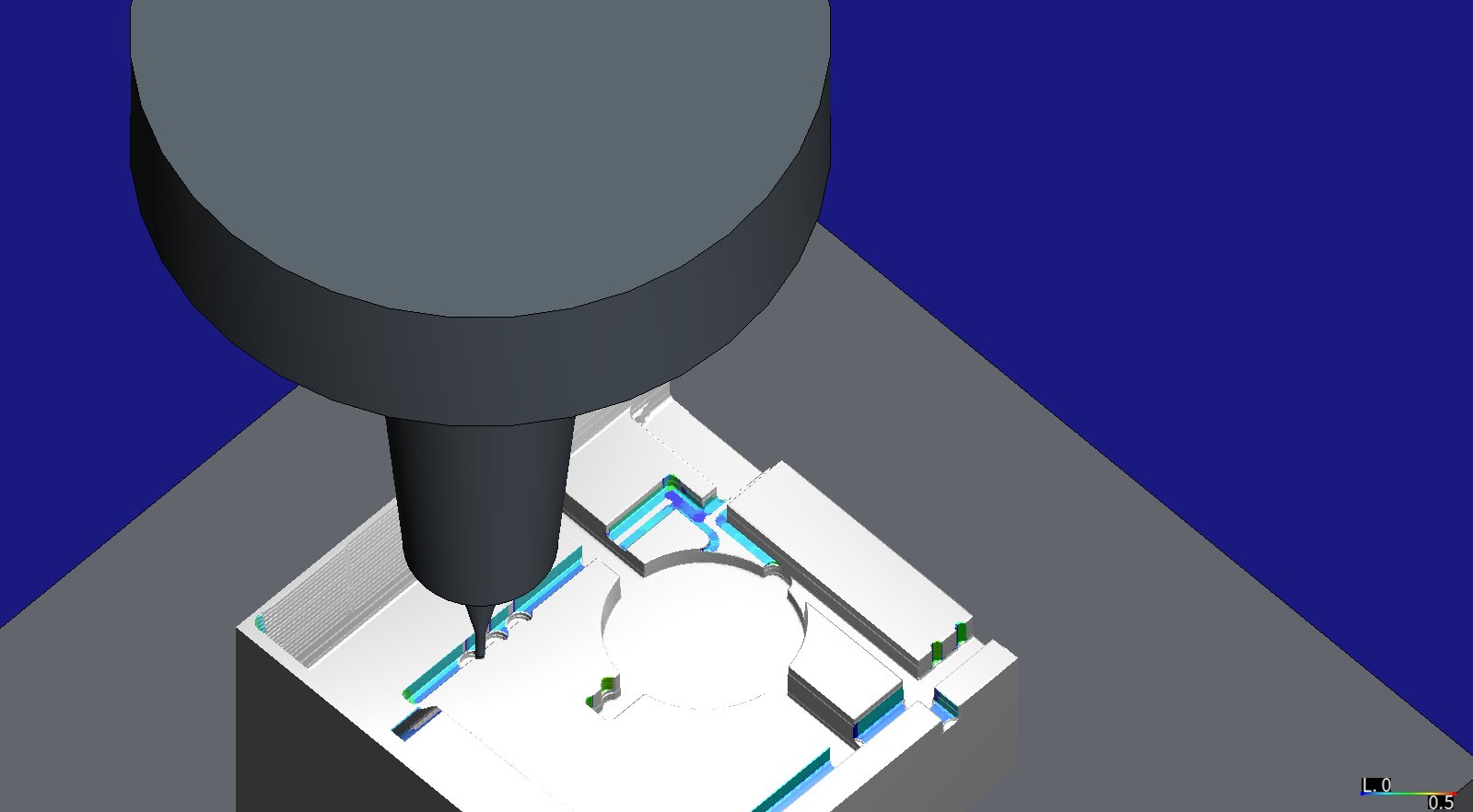
The trimmed B insert on the revised programs: the NS TOOL MHR230R Ø1 R0.1, 18 mm out of a generic 4.5° shrink-fit chuck, halfway along the rib slot at Y ≈ 33 (Z −14.685), the faces it has just cut coloured by that step's stress ratio from 0 to 0.5, almost all blue to cyan. The circle in the middle is the boss, left for EDM; top right, the corner of a clip box. Captured on HiNC 3.2.43.
The small tool meets a corner head-on
- Situation. In the rib slots the Ø2 mm tool returns to the same point on every level: where the path runs into a slot just as wide as the tool and turns back (by 140–157°), a slot's dead end, an inside corner. 97 of its 202,736 steps read a stress ratio over 0.5, up to 1.03 (95 at such points, one on a sliver of the false step above, one at the end of a ramp); the median was 0.11.
- Risk. Judging a tool overloaded on a reading, or slowing a whole program for 97 steps.
- How it was noticed. The case's pass criterion — every step of the small tools under 0.5.
- Resolution. Two agents replayed the cut exactly and a third checked HiNC's side. Each time the tool comes back to such a point, the corner its previous level left with its 0.2 mm radius stands right in front of it: the real section of that last tooth's cut is about 1.6–1.8 times a straight full-width cut's (2.2 in a synthetic dead end; at some such points not at all). HiNC reads 3.3 to 6.8 times; 81 of the 97 steps sit on one plateau, 49.1 N, whatever the height of the wall ahead. Estimated from the straight slot's ratio, about 0.15, times the real factor, the real stress ratio stays at about 0.24–0.27 at most such points and up to about 0.33 in the synthetic dead end (inferred, not recomputed with HiNC's force model): the crossing of 0.5 is mostly HiNC's excess. Both halves answer to feed: the program now runs every pass in a slot little wider than the tool at the catalogue's slotting feed (750 mm/min, where it had used it only for a level's first pass) and slows to 375 mm/min for the last 0.3 mm into a turn of 60° or more and the first 0.15 mm out of it, the end of an open pass, the first 0.3 mm of every pass and the short links at depth that end at the next pass's start.
- Evidence it held. On the trimmed patch the steps over 0.5 fell from 97 to 29 with the rasteriser fix and a first feed rule, and to 1 with the final one; the 99th percentile went from 0.44 to 0.22, for 12 % more time on this program (49.4 to 55.5 minutes, about 2 points of it a feed the program failed to write; see the next dilemma). The one left ends a ramp into a slot's end, already at 375 mm/min, where HiNC removes 8.3 times the exact volume in one step.
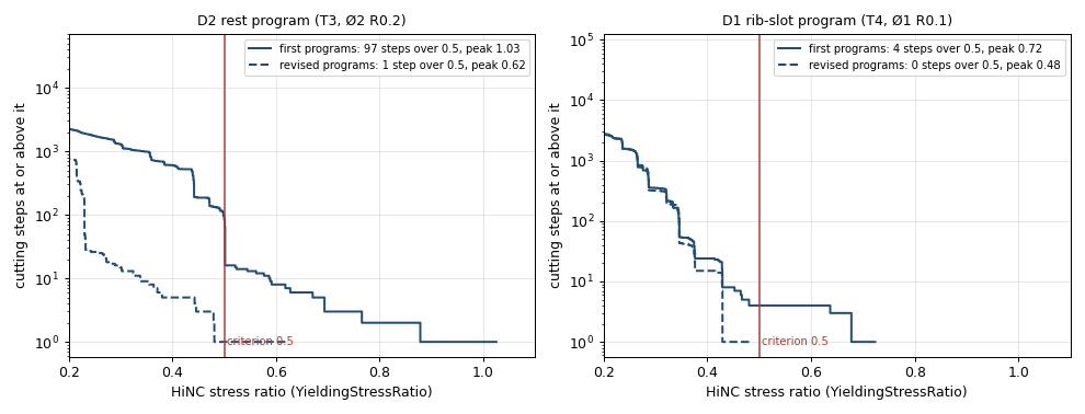
The trimmed B insert, HiNC 3.2.43: the number of cutting steps at or above each stress ratio, the first programs (solid) and the revised ones (dashed). Criterion C2 asks every step of these tools to stay under 0.5.
The trimmed B insert before and after the revision (the Ø1 mm rows from a play that followed an intermediate Ø2 mm program, which differed from the final one only in its feeds and left the same stock):
| Trimmed B insert | First programs | Revised programs |
|---|---|---|
| Ø2 mm tool, steps over a stress ratio of 0.5 | 97 (peak 1.03) | 1 (0.62, a ramp into a slot's end, already at 375 mm/min, where HiNC removes 8.3 times the exact volume) |
| Ø2 mm tool, stress ratio p99 | 0.44 | 0.22 |
| Ø2 mm tool, simulated time | 49.4 min | 55.5 min |
| Ø1 mm tool, peak stress ratio | 0.72 | 0.48 |
| Ø1 mm tool, neck flags | 8 | 0 |
| Ø1 mm tool, tip deflection p99 / peak | 19 / 60 µm | 19.0 / 34.4 µm (the revised program replayed on HiNC 3.2.45 for the NC-optimization study, over its cutting steps) |
| Ø1 mm tool, levels along the skirt's outer wall (X < −109.2; Y 12–16 / Y 24–26) | 52 / 64 | 4 / 2 (at its foot) |
A feed the agent's NC writer dropped
- Situation. Criterion C4 (a) holds HiNC's time for each program to the plan's own estimate, the path at its feeds plus the rapids. On the revised trimmed A insert the Ø2 mm program took 2.98 minutes against 2.35 planned, 27 % over; every other program was within 4 %.
- Risk. A program that runs other than it was written: slower where a faster feed was meant, or at the full feed where the program meant to slow down into a corner.
- How it was noticed. The ±10 % band of C4 (a).
- Resolution. The agent's NC writer leaves out a move too short to show at four decimals, but it recorded that move's feed and G code as written; the next move at that feed then carried no F word and ran at the previous one. The writer now records a feed or a G code only on a line it writes, and every program was written again from unchanged paths. Compared line by line, every program kept its lines, and only F words and G codes changed: the old Ø2 mm programs had lost an F word on 5 lines of the trimmed A insert's (25.8 % longer), 117 of the trimmed B insert's (2.1 %) and 622 of the whole B insert's (0.7 %), and no other program had lost one; the others differ in one line, a rapid that now repeats the G00 already in force.
- Evidence it held. At acceptance the Ø2 mm programs took 180.40 minutes against 180.59 planned on the B insert and 9.79 against 9.76 on the A insert.
A rapid that left one square of the stock
- Situation. In the whole B insert's acceptance the semi-finishing stage read the roughing's
stock from its file and cut as planned up to one rapid: a link the agent's CAM had written as a
single
G00that went 80 mm across and 16.5 mm down from the safe height to the next level's start. - Risk. Every later program meets no stock and each run still ends “Finished”: an acceptance of a stock that is not there.
- How it was noticed. The finishing stage touched the stock on 801 of its 343,321 steps, where the trimmed patch's finishing had touched it on nearly a third of them; the stock file the stages write had fallen from 70.7 MB after roughing to 0.46 MB after semi-finishing.
- Resolution. Read alone, the roughing's file gave the whole stock back. The semi-finishing cut normally up to that rapid; one step of it, with the tool's tip 4.4 mm above HiNC's own stock, was marked as touching the stock with no volume removed and a rapid-cut warning, and from that step on the stock was one flat 16 mm square around it. Played again to just past that line on the stored file, HiNC repeated it step for step in three minutes; with the 22 rapids in that stretch that descend while they move split into a move across and a vertical descent, it kept the whole stock and warned of nothing. The agent's CAM now descends only vertically — the safer way on a machine too, whose rapids may move each axis at its own speed — and its stage player stops when a stage's exported stock shrinks below 30 % of the previous stage's, rather than hold a lock other agents wait on.
- Evidence it held. Played again with every rapid descending vertically, both inserts kept their whole stock through every program: the stock files grew from about 70 MB after roughing to 1.2 GB (B) and 1.5 GB (A) after the last program, and no rapid that moves while it descends was left in any program. The rapid-cut warnings left are rapids along the tool axis beside a fresh cut: on the B insert five that touched it for no volume, on the A insert 17 drill retracts that took a ring off a hole's wall (below).
Results and benefits
Measured on HiNC 3.2.43, each insert accepted on one valid play, one program per run, at the mesh widths above; the comparison with the design is the agent's column-by-column check of the stock HiNC exported after the last program (0.05 mm grid, steep faces left out), and the coloured pictures are HiNC's own geometry difference.
The whole B insert (the moving half, five programs):
| Program | Steps | Touching the stock | HiNC / plan, min | Stress ratio p50 / p99 / peak | Steps ≥ 0.5 / ≥ 1 | Tip deflection p99 / peak, µm |
|---|---|---|---|---|---|---|
| Roughing, Ø10 | 121,065 | 54,065 | 98.67 / 98.64 (+0.03 %) | 0.16 / 0.41 / 0.52 | 124 / 0 | 60.7 / 76.8 |
| Semi-finishing, Ø6 R0.5 | 91,355 | 54,328 | 22.04 / 22.02 (+0.10 %) | 0.13 / 0.51 / 0.97 | 643 / 0 | 76.6 / 153.9 |
| Finishing, Ø6 R0.5 | 345,495 | 244,395 | 113.24 / 113.24 (+0.01 %) | 0.02 / 0.08 / 0.51 | 1 / 0 | 12.6 / 77.4 |
| Rest, Ø2 R0.2 | 1,200,719 | 186,987 | 180.40 / 180.59 (−0.10 %) | 0.09 / 0.23 / 1.05 | 8 / 1 | 52.6 / 234.7 |
| Rib slots, Ø1 R0.1 | 1,638,058 | 393,475 | 305.62 / 305.90 (−0.09 %) | 0.08 / 0.29 / 1.07 | 32 / 3 | 19.5 / 78.5 |
| Total | 3,396,692 | 719.97 / 720.38 (−0.06 %) |
The tip deflection is that of the same five programs replayed on HiNC 3.2.45 for the NC-optimization study, over the steps that cut (more than 0.01 mm³/s).
The whole A insert (the fixed half, six programs):
| Program | Steps | Touching the stock | HiNC / plan, min | Stress ratio p50 / p99 / peak | Steps ≥ 0.5 / ≥ 1 |
|---|---|---|---|---|---|
| Roughing, Ø10 | 113,589 | 62,902 | 57.97 / 57.95 (+0.04 %) | 0.20 / 0.30 / 0.52 | 26 / 0 |
| Semi-finishing, Ø6 R0.5 | 112,654 | 68,569 | 21.49 / 21.45 (+0.17 %) | 0.12 / 0.45 / 0.60 | 276 / 0 |
| Finishing, Ø6 R0.5 | 371,469 | 246,433 | 113.66 / 113.66 (0.00 %) | 0.02 / 0.06 / 0.23 | 0 / 0 |
| Rest, Ø2 R0.2 | 282,334 | 12,789 | 9.79 / 9.76 (+0.36 %) | 0.07 / 0.16 / 0.21 | 0 / 0 |
| 582 pin holes, Ø1.8 drill | 298,246 | 37,282 | 17.15 / 17.10 (+0.27 %) | 0.24 / 0.24 / 203.9 | 17 / 17 |
| Boss pin holes, helical, Ø6 | 41,449 | 32,996 | 14.89 / 14.85 (+0.30 %) | 0.04 / 0.05 / 0.06 | 0 / 0 |
| Total | 1,219,741 | 234.95 / 234.77 (+0.08 %) |
- Time. Every program of the B insert came within 0.10 % of the agent's own estimate, every one of the A insert within 0.36 % (criterion C4 (a)). The whole B insert is 12.0 hours of machining, 42 % of it the Ø1 mm tool in the rib slots and 25 % the Ø2 mm tool — more than half on the two small rest tools (C4 (c)). The A insert is 3.9 hours: 48 % the finishing program (the plug, its tabs and the parting face), 25 % roughing, 9 % semi-finishing, 7 % drilling the 582 pin holes; the pair of inserts is 15.9 hours of milling and drilling before EDM.
- Against the design (C2 (c), C6). On 36,559 mm² of flat and gently sloped faces the B stock sits at a median of +0.002 mm on the floors and 0.000 on the parting face, which the programs do not touch, but for a line one cell wide along the rim that reads down to −0.077 mm. Everything left more than one mesh width (0.0625 mm) above the design, 70.5 mm², is stock the agent's own model also leaves: the EDM regions, the rib-slot ends at the skirt wall that the long-neck tool would have reached, and the small fillets at the foot of walls. Cut below the design by more than 0.0625 mm: 8.1 mm², mostly lines one cell wide along wall edges; by more than the finishing mesh's 0.125 mm: 0.1 mm², single cells on the steep slopes at the skirt's ends, the deepest −0.187 mm.
- Loads (C2 (b), C5). The spindle peaked at 0.56 of its rating (roughing). Four steps of the rest tools reached a stress ratio over 1: one of the Ø2 mm tool's beside a row of 1 mm teeth on the plateau's side, and three of the Ø1 mm tool's turning 119° round those teeth at their top with the whole 0.8 mm flute engaged — the Ø1 mm program has no corner slowdown, only the Ø2 mm one does. Of the Ø1 mm tool's other 29 steps over 0.5, about 20 run their whole flute along a thin layer at slot ends and walls, the case HiNC was found to over-read on the trimmed patch; a few cut nearly full width at slot ends.
- The shank collisions (C1). HiNC flagged the Ø1 mm tool against the stock 48 times, at a few
slot ends and rib crossings, level after level, and the Ø2 mm tool 3 times, all as
Collided(Workpiece,CutterShank). Checked at each of the Ø1 mm tool's 48 steps, its neck clears the walls of the design by 0.025 mm — exactly its relief, the 0.95 mm neck under a 1 mm flute — and HiNC's own exported stock by 0.005–0.075 mm (median 0.017): no stock reaches into the neck, and most of the flags fall within one 0.03125 mm mesh width. On a machine, 0.025 mm is also all the margin a deflecting tool has, so these are the places where the neck may rub. - Rapid grazes (E). Five rapids along the tool axis touched the stock beside a fresh cut for no measurable volume (0 to 4e-5 mm³): four retracts, the reading another case recorded as a tool that rubs on its way out, and one vertical descent to 1 mm above the next level. The stock stayed whole after every program.
- Run cost. The five plays took 1 h 54 min on the shared 32-thread server; the process peaked at 15 GB while playing and at 30.9 GB while HiNC computed the geometry difference at the end.
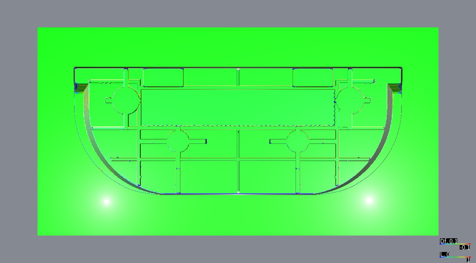
HiNC 3.2.43's geometry difference over the whole B insert, top view, ±0.1 mm. The blue and red edges are walls and slot sides; the two white spots are reflections of the scene's lights.
- The A insert against the design. Its parting face, which the finishing program cuts, sits at +0.006 mm with nothing below the design; the plug's face at a median of +0.005. The 24.6 mm² left above the design by more than 0.1 mm is again all stock the model leaves (two corners of the plug's ends); cut below it by more than 0.125 mm, 0.1 mm² of single cells, the deepest −0.365 mm at one corner of the plug's lower step. The four boss pins' holes are 15.0 mm deep, as planned. The design heights carry no fit holes, so the holes are checked one by one instead.
- The drilling. Every hole drilled at 116.8 N, a stress ratio of 0.24 and 0.01 of the spindle's
power. At 17 of the 582 holes, the
G81rapid retract from the bottom took a ring off the wall (0.14–0.78 mm³), and the first step of each of those 17 retracts read 1,916–5,460 N and a stress ratio of 99 to 204 (the second reads nothing), with rapid-cut warnings: the reading the trimmed patch already showed at 2 of its 39 holes. A real drill does not cut that ring on its way out. - Run cost. The six plays took 49 minutes. The server process, which carried about 25 GB from earlier work into this play, peaked at 43.6 GB while HiNC computed the geometry difference at the end.
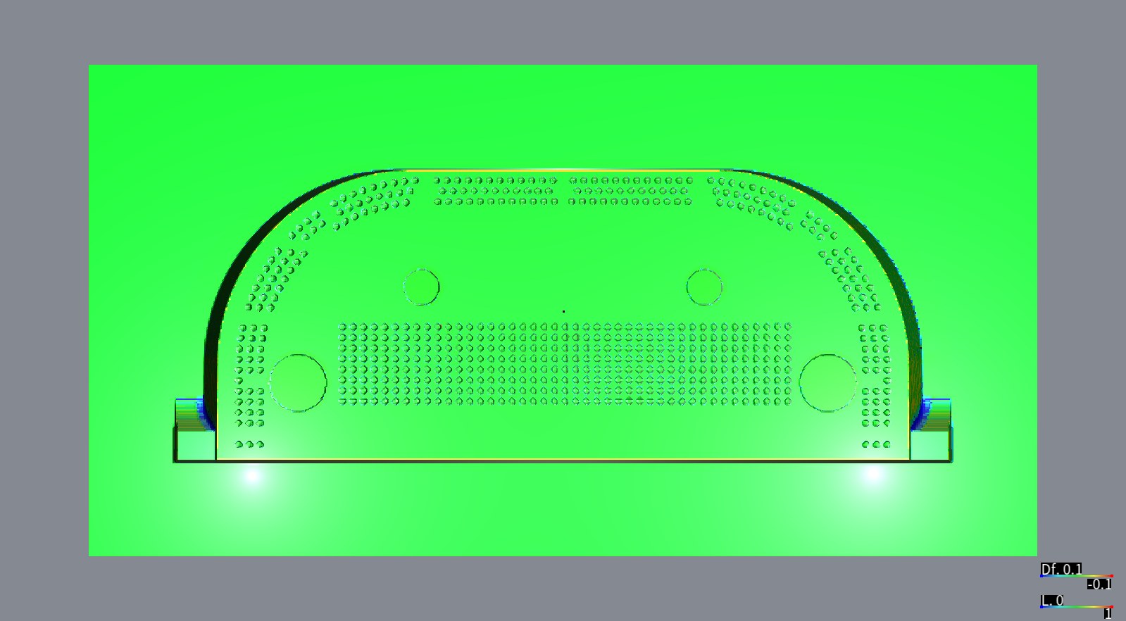
HiNC 3.2.43's geometry difference over the whole A insert, top view, ±0.1 mm: the plug, its 582 pin holes and the four boss pins' holes all on the design. The two white spots are reflections.
The comparison with the design face by face, from the agent's column-by-column check of the stock HiNC exported after the last program (0.05 mm grid, steep faces left out):
| Face | B insert | A insert |
|---|---|---|
| Parting face | 20,299 mm², not machined: 0.000 mm at the 99th percentile, but for a line one cell wide along the rim down to −0.077 mm | 21,757 mm², finished: +0.006 mm at the median and the 99th percentile, nothing below the design |
| Floors and gentle slopes (B), the plug's face (A) | 11,786 mm²: +0.002 mm at the median, +0.005 at the 99th percentile | 12,545 mm²: +0.005 mm at the median, +0.010 at the 99th percentile |
| Above the design by more than 0.0625 mm (by more than 0.1 mm) | 70.5 mm² (56.0 mm²), all of it stock the plan also leaves | 51.8 mm² (24.6 mm²), all of it stock the plan also leaves |
| Below the design | 8.1 mm² by more than 0.0625 mm, mostly lines one cell wide along wall edges; 0.1 mm² of single cells by more than 0.125 mm, the deepest −0.187 mm | 0.1 mm² of single cells by more than 0.125 mm, the deepest −0.365 mm |
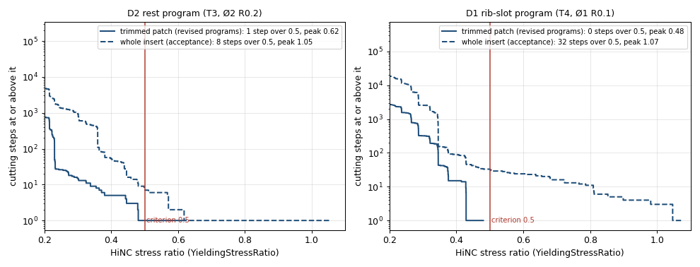
The rest tools' stress ratio on the B insert, HiNC 3.2.43: the number of cutting steps at or above each value, on the trimmed patch with the revised programs (solid) and on the whole insert at acceptance (dashed). The whole insert's longer tail sits at the row of teeth on the plateau's side and at more slot ends.
The criteria on the trimmed patches, the B insert's on its revised programs and the A insert's on its first ones, before the whole inserts were played:
| Criterion | Trimmed patches |
|---|---|
| E, run evidence | B insert, revised programs: met, every program touching the stock with no message but progress and success. First programs: not met, 1–2 Play-RapidCut--Detected on each of the Ø2 mm, Ø1 mm and drilling programs (on the Ø2 mm and Ø1 mm tools grazes of 0 mm³) and 8 collisions on the Ø1 mm program |
| C1, holder and shank | B insert, revised programs: met, no collision; the first programs' 8 neck flags do not hold in the exact geometry |
| C2 (a), depth and width | depth not met (contact height), width met |
| C2 (b), rest tools under 0.5 | Ø1 mm tool met (peak 0.48); Ø2 mm tool not met by 1 step (0.62, the end of a ramp, which HiNC over-reads) |
| C2 (c), C6 | left to the whole inserts' comparison with the design |
| C3, rib-slot deflection ≤ 10 µm | not met: the Ø1 mm tool's tip deflection 5.9 µm at the median, 19.0 at the 99th percentile and 34.4 at its peak (the revised program replayed on HiNC 3.2.45 for the NC-optimization study, over its cutting steps), more than three times the cantilever estimate of about 1 µm; HiNC's deflection is its force times the tool's compliance step by step, so it is the force reading that is high (the Ø1 mm tool's over-read in A false step on the skirt's wall) |
| C4 (a), time within ±10 % | met |
| C5, power, torque, stress ratio | B insert met (largest 0.97, semi-finishing); A insert not met: the two drill-retract steps at 133–135 (HiNC's reading) |
The criteria as written, on the whole inserts:
| Criterion | B insert | A insert |
|---|---|---|
| E, run evidence | not met: 5 rapid grazes and 51 shank collisions | not met: 17 drill-retract rapid cuts |
| C1, holder and shank | not met as written: 51 flags; the 48 located clear the design by 0.025 mm and HiNC's stock by 0.005–0.075 mm (median 0.017) | met: none |
| C2 (a), depth and width | depth not met (contact height), width met (no step over the diameter plus one mesh width) | depth not met, width met |
| C2 (b), rest tools under 0.5 | not met: 8 + 32 steps | met: 0 steps |
| C2 (c), against the design | left stock met (70.5 mm² beyond 0.0625 mm, all of it also left by the plan); gouge not met as written: 8.1 mm² beyond 0.0625 mm, 0.1 mm² beyond 0.125 mm, deepest −0.187 | left stock met (51.8 mm² beyond 0.0625 mm, all of it also left by the plan); gouge not met as written: 0.1 mm² beyond 0.125 mm, deepest −0.365 at one spot |
| C3, rib-slot deflection ≤ 10 µm | not met: over the whole Ø1 mm program, mostly the rib slots, 6.0 µm at the median, 19.5 µm at the 99th percentile, 78.5 µm peak at the row of teeth (the program replayed on HiNC 3.2.45 for the NC-optimization study, over its cutting steps) | — |
| C4 (a), time within ±10 % | met: within 0.10 % | met: within 0.36 % |
| C4 (c), time shares | reported, not judged: the Ø1 mm tool 42 % and the Ø2 mm tool 25 % of 12.0 h | reported, not judged: the pin holes 7 % of 3.9 h |
| C5, power, torque, stress ratio | power and torque met (0.56); 4 steps over 1 (the Ø2 mm tool 1, the Ø1 mm tool 3) | power and torque met (0.85 and 0.31, at a drill retract); 17 drill-retract steps over 1, at 99–204 (HiNC's reading); the drilling itself 0.24, at 0.01 of the power |
| C6, parting face and shut-off | face met (untouched, 0.000 at the 99th percentile) but for a one-cell line along the rim to −0.077 mm; the shut-off judged by HiNC's picture only | face met (+0.006 mm); the shut-off judged by HiNC's picture only |
For a machining engineer. HiNC showed before any steel was cut that the agent's programs do what they claim: every program within 0.4 % of its estimate, the stock after each program as the model expected (but for 26 mm² of slivers the B roughing left, which the semi-finishing took), the finished faces on the design at a median of a few microns, and everything left where the plan said no cutter reaches. It also showed where the small tools are worked hardest — the row of teeth on the plateau's side, the rib-slot ends by the skirt wall — and that the Ø1 mm tool's neck runs 0.025 mm from the walls its own flute cut, which on a real machine is the margin a deflecting tool has. More than half of the B insert's twelve hours goes to the two small rest tools, a number to weigh against an extra EDM electrode.
For a teacher or a student. How an injection-mould insert is derived from the moulded part — the draft decides which half forms each face and where the pins stand; why a mould shop leaves deep bosses and thin gussets to EDM; how rest machining with small tools follows the stock the larger ones left; and how a simulation's readings — a cutting depth that is the height of contact, a load over-read at a corner — have to be read before they are judged.
For someone weighing the approach. From a published part to two inserts played through acceptance, several criteria not met as written (the table above), the agent derived the mould, wrote its own CAM, set the criteria before the first play and checked HiNC's stock against its own model after every program. HiNC caught three mistakes in the agent's own code — a rasteriser that bent the mould, a writer that dropped feeds, rapids that descended while they moved — and the agent ran down an engine defect that ends a run “Finished” with nothing cut. The acceptance plays took under three hours on a shared server, and 31 and 44 GB of memory at their peaks, the second with about 25 GB carried over from earlier work.
Honest limits
- The mould is the agent's. Shrinkage, parting, the split into inserts, the pins and the EDM regions are derived or chosen; no mould maker checked them. The gate, the ejector pins, the cooling and the pin relief holes of a real mould are not designed, and mould flow is not simulated.
- The comparison cannot see a mistake in the mould. The design model HiNC compares the machined stock with and every program come from the same height field the agent derived from the part; an error in that derivation, like the false step on the skirt's wall, leaves the comparison clean. The check on it is the part itself: odd crossings, none after the fix.
- The finish is not simulated. MT-11000 texture, polishing, reaming the pin holes and the EDM are outside HiNC; the comparison shows the milled surface only.
- Catalogue tools in generic holders. Geometry and base conditions are the makers'; where the tool table marks a condition derived or chosen, the agent scaled or picked it. The edge hone, rake and relief, which the catalogues leave out, are the agent's; the carbide grade's properties, the TiAlN coating and the P20 cutting data are HiNC's shipped ones, not the makers'; the shrink-fit chucks are generic, not a vendor's.
- The agent's reach check skips what is no wider than the cutter: the straight necks of the small tools. In a height field such a neck cannot meet the design, only stock an earlier level left within about a cell of the wall; HiNC's collision check covers it.
- Loads HiNC over-reads. Where the Ø2 mm tool meets a corner head-on HiNC reads 3.3–6.8 times a straight full-width cut's load where the real section is about 1.6–1.8 times; where the Ø1 mm tool runs its whole flute along a thin layer on a wall, HiNC's removal per step is 2.3–7.4 times the exact volume; a rapid retract grazing a freshly drilled hole's wall reads up to 5.5 kN and a stress ratio up to 204 in one step (17 of the A insert's 582 holes), flagged by HiNC as a rapid cut. Its cutting depth is the height of the tool's contact, not the chip's thickness. The criteria are judged on HiNC's readings as written.
- The comparison with the design is the agent's. HiNC's geometry difference colours the stock and reports counts, not a distribution; the numbers on this page come from the agent's column-by-column check of the stock HiNC exported, which judges flat and gently sloped faces only. The skirt's walls, the 5° shut-off and the holes' walls are judged by HiNC's picture. The design model is an open surface meshed from the height field; HiNC warns of that and compares anyway.
- Three shank collisions of the Ø2 mm tool were not located: the evidence of that program recorded their number but not their steps.
- A three-axis machine with no dynamics. Rapids are 24 m/min on every axis and the machine's acceleration is not modelled, so the simulated time is the path at its feed plus the rapids.
- The cutter is a 24-sided prism in this mode, and the stock a mesh of the widths above: a surface can only be judged to about one mesh width.
- Each program ran as its own run, and every rapid descends vertically because of the engine defect above; HiNC was not asked to play a whole insert in one run, nor a rapid that descends while it moves.
What a reader can take to their own case
- Derive the mould half by half from the part's own draft: measure a face at both ends before deciding which half forms it.
- Check the derivation itself, not only the machining: a vertical line through a closed part crosses it an even number of times, and a count that says otherwise is a mistake somewhere.
- Decide what is milled before writing a program, and write the rule for dropping a tool before the first play.
- Read HiNC's cutting depth as the height of contact, not the chip; judge small tools by force and stress, and slow them where they meet a corner head-on.
- Export the stock after each program and compare it with what the next program expects; a program that cuts nothing looks like a finished run.
- When each program reads its stock from the previous one's file, compare the size of the stock it exports with the previous one: a stock that shrinks to a fraction of itself has collapsed, and every later program would read it and still finish.
- Write rapids that go across at one height and descend vertically. A rapid that moves and descends at once may not follow a straight line on a machine whose rapids drive each axis at its own speed, and it is the move after which HiNC held one cell of the stock.
Source and licence
- Source. Telecom Infra Project, OpenCellular, https://github.com/Telecominfraproject/OpenCellular,
folder
hardware/connect-1/:cad/individual_parts/227-001264_SHORTY_ANTENNA_COVER.stepanddrawings/227-001264_SHORTY_ANTENNA_COVER.pdf(read 2026-09-30). Search terms if the link moves:OpenCellular 227-001264 SHORTY ANTENNA COVER. - Licence. The repository's README states that the documentation under
hardware/is licensed under Creative Commons Attribution 4.0 (CC BY 4.0);LICENSE-HARDWAREholds the legal text. The drawing frames still read “CONFIDENTIAL” and “DRAFT RELEASE 30/11/2016”, left over from before release; the repository publishes them under the licence above. - Attribution. “OpenCellular Connect-1 hardware, Telecom Infra Project, https://github.com/Telecominfraproject/OpenCellular, CC BY 4.0. Mould design and machining set-up by Tech Coordinate's agent.” Provided by the licensor without warranty.
- Changed. The mould — shrinkage, parting surface, both inserts, the pins and EDM regions — the stock, the tools and every program are the agent's. The part model and the drawing are used as delivered; of the drawing, only the notes on sheet 1 are reproduced, cropped (under The case), and the part's picture is rasterised from the STEP model by the agent's script. The OpenCellular logo and the light pipe (227-001263) are not used.
- Backup. The company site keeps a copy of the original files.
See Also
- Antenna-Cover Injection Mould, Optimized — HiNC's feed optimization on this case: the moving insert from 12.0 to 7.9 hours, and no feed holds the Ø1 mm tool within 10 µm
- Showcase — the other cases and how a case page reads
- Replay Acceptance over the HTTP API — watching a play and accepting on evidence
- Mesh Resolution — the cube edge each program was played at
- Evaluating Process Machinability — the stress ratio the rest tools were judged by