Heatsink Porthole Die: An Extrusion Die Rebuilt from a Paper's Drawings, and Where Milling Gives Way to EDM
A porthole die for an aluminium heatsink is everyday work in an extrusion die shop: a Ø180 mm steel die in two plates, two portholes split by a bridge, a welding chamber, a pocket, and a die orifice with twelve fins down to 1.51 mm thick. A paper by Truong, Hsu, Tong and Sheu (Metals 2020) designed such a die by simulation, had it made, and extruded a heatsink profile that met its tolerances on a 930-ton press. The paper publishes drawings and a handful of dimensions, not a CAD model or a process. An AI agent rebuilt both plates from the drawings, decided what a die shop mills and what it leaves to wire EDM, wrote four set-ups and eight Fanuc programs, and played them in HiNC through the web API. HiNC's first play caught the agent's own program running rapid moves along the roughing walls; once fixed, the four set-ups played at 0.25 mm with no alarm, the milled faces of the upper plate and the pocket came within ±0.15 mm of the model, and the porthole roughing used under a fifth of the spindle's continuous power. The numbers also drew the line a die shop draws by experience: the relief behind the twelve fins takes a Ø3 long-neck cutter seven hours, bends it a tenth of a millimetre, and leaves about 2 % of that relief out of its reach, so that part goes to EDM.
Everything here is simulated: no die was cut on a real machine. The die on this page is the agent's model after the paper's figures, not the authors' CAD. Each dilemma below gives the risk, how it came to light, the resolution and the evidence that it held. The built projects were the agent's working material and are not distributed.
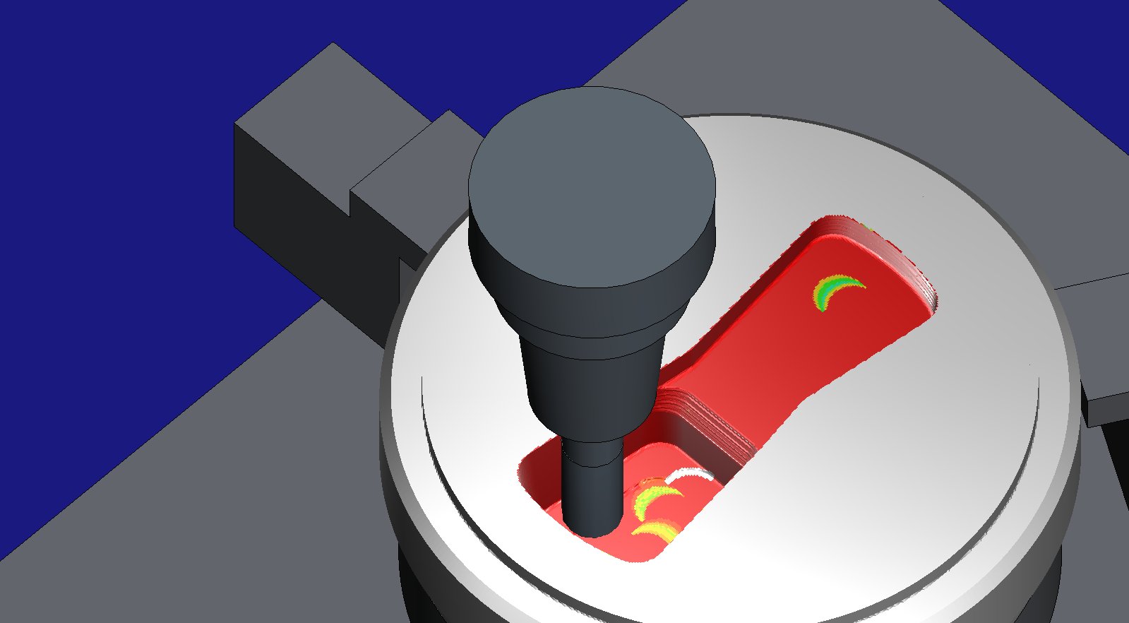
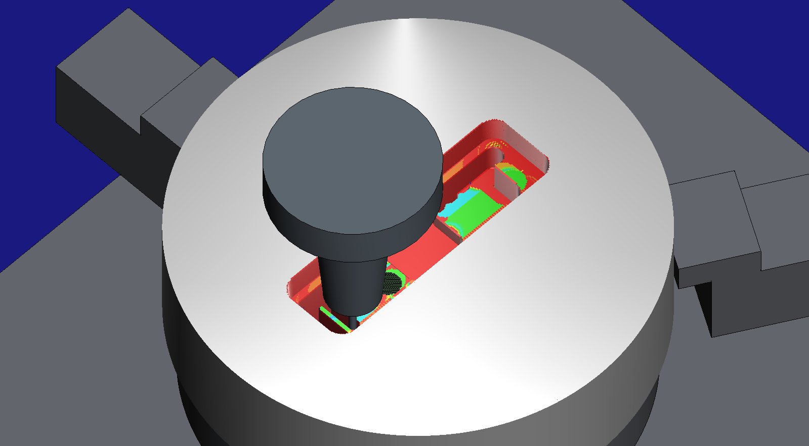
The upper plate on HiNC's canvas, captured while the roughing played: the Ø16 end mill in its shrink-fit chuck is halfway down porthole 1, and the stock is shown as cut at that moment. Captured on HiNC 3.2.43.
The case
The paper gives the die's purpose and its structure in text and figures:
- the heatsink profile, 95.95 × 20.2 mm with a 4.04 mm base, a 23.13 mm central block, six 2.57 mm fins on one side and three 1.51 mm fins, an 8.32 mm fin and an outer fin on the other, with a 0.2 mm wave on four fin faces (Fig. 1);
- the die, “an upper and a lower part, with a height and a diameter of 90 and 180 mm”, H13 steel, a 130 mm container (Sec. 2, Table 2);
- the initial layout (Fig. 2) and four correction steps: porthole 2 reduced by 3 mm, the pocket modified, the bearing lengths adjusted, the bridge chamfered (Figs. 6–12, Table 3), ending in the proposed die of Fig. 21, the one that was made and extruded;
- the bridge 18 mm wide with a 10 mm rear tip and a 50° tip angle, a 4 × 25° chamfer, a 13 mm welding chamber, a 7° relief on the portholes, corners R63, R60 and R8, and every bearing length (Fig. 10).
What it leaves out: the plates' heights, the portholes' long edges and inner corners, the pocket's outline in numbers, the run-out steps' plan, the offset of the relief behind the bearing, the fin spacing on the right-hand side, and anything about how the die was machined.
What the agent built
A die shop makes this kind of die in roughly these steps, and the agent chose which of them to simulate:
| Step | Method | In this case |
|---|---|---|
| Turning | a lathe | not simulated: the blanks start as turned, with the upper plate's spigot, the lower plate's rim and the outer steps |
| Upper plate: portholes, welding chamber, bridge | a machining centre | simulated: from the joint face, the portholes roughed and finished through the 45 mm plate with the welding chamber; turned over, the bridge's 4 × 25° top chamfers |
| Lower plate: the pocket (the second welding chamber) | a machining centre | simulated: the bow-shaped pocket, 5 mm deep |
| Lower plate: the relief at the back | a machining centre or EDM | simulated: run-out step 2 (10 deep) and the profile-shaped run-out step 1, deep enough to leave each segment's bearing length |
| Die orifice and bearing | wire EDM | not simulated, and not milled in its place; the 0.2 mm waves are on the bearing too |
| Heat treatment, nitriding, polishing | — | not simulated; FDAC is pre-hardened (about HRC 40) and is milled at that hardness |
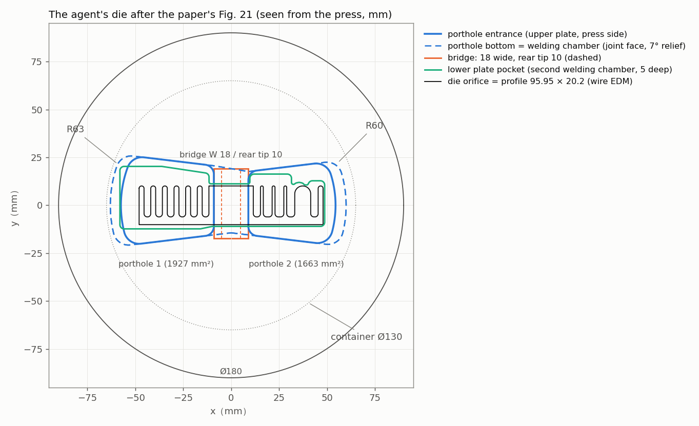
The die as the agent read it from the paper, seen from the press side. The portholes' outer walls open 7° towards the lower plate, so the bottom outline (dashed) lies outside the entrance (solid).
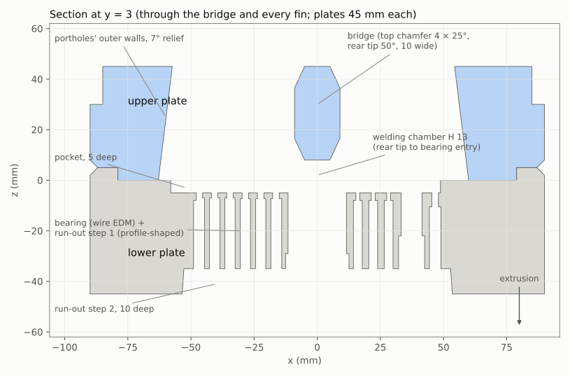
The same die cut through the bridge and every fin: two plates of 45 mm, the portholes' outer walls and the bridge's top chamfers opening opposite ways, and below the joint the pocket, the bearing and the two run-out steps.
Each value is marked read (the paper states it), measured (read off a figure at its drawing scale), derived or chosen (the agent's decision).
| Item | Value | |
|---|---|---|
| Which die | the proposed die of Fig. 21 (Table 3, step 4), the one made and extruded | read |
| Plates | upper and lower, 45 mm each at the centre, spigot Ø158 × 5, upper top step Ø170 × 15 | measured (Fig. 12) |
| Portholes | long edges closing 0.1206 towards the bridge, outer ends R63 and R60 at the bottom, 7° relief on the outer walls, outer corners R8, inner corners R5 | read, measured, chosen (R5) |
| Bridge | 18 wide, rear tip 10 at 50°, top chamfer 4 × 25° (read as 4 mm across at 25° from the vertical, 50° between the two faces), rear tip 8 mm above the plates' joint | read, derived |
| Welding chamber | 13 mm from the rear tip to the bearing entry: 8 in the upper plate, 5 in the pocket | read, derived |
| the modified bow-shaped outline of Fig. 8, 5 deep, corner radii ≥ 2.2 | measured, chosen | |
| Fins | left: six 2.57 mm fins at a 6.068 pitch (gaps 3.498); right: gaps 3.74, 4.59, 4.59, 4.18 and 3.89 | derived, measured (Fig. 1a) |
| Drawing scales | Fig. 21a 2.699 px/mm (the Ø180 circle), Fig. 12 8.43 px/mm (the 90 mm height), Fig. 1a 4.669 px/mm (the 95.95 mm profile) | derived |
| Bearing | wire-cut, not milled; its lengths (1.2–24 mm, Fig. 10) set by how deep the relief behind it goes | read |
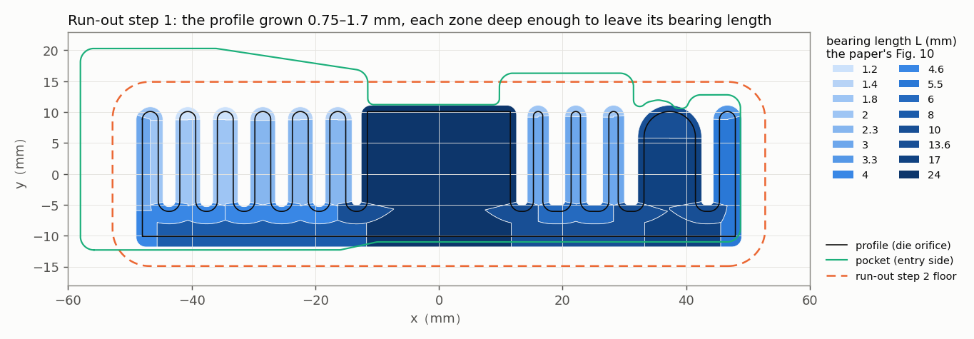
| Run-out step 1 | the profile grown 1.0 mm (0.75 on the 2.57 mm fins, 1.7 under the base), in 16 depth zones, each leaving its segment's bearing length | chosen, derived |
| Run-out step 2 | 105.6 × 29.8 at its floor, 10 deep, 4° draft | measured, chosen |
| Material | FDAC (pre-hardened SKD61-type, about HRC 40) for the paper's H13; HiNC's FDAC.default material and cutting parameters |
chosen |
| Machine | HiNC's three-axis skeleton Empty-wXYOZSt, travels 800 / 500 / 500, rapid 24 m/min |
chosen |
| Spindle | generic BT40, 12,000 min⁻¹, 11 kW continuous and 15 kW short-term above 1,500 min⁻¹ | chosen |
| Fixture | a plate, a riser ring and three jaws on the Ø180; under the upper plate's billet face the riser is a ring Ø134 inside, so the through portholes (their entrance reaches R57.5) stand over air | chosen |
| Controller | Fanuc; G54 set to program zero after the reset | chosen |
| Program zero | on the face the tool meets, on the die's axis, in each set-up | chosen |
Two checks tell whether the figures were read right. The paper gives the portholes' areas, 1960 and 1702 mm²; the model's entrance areas are 1927 and 1663 mm² (−1.7 %, −2.3 %). The extrusion ratio 10.73 with the 130 mm container implies a 1237 mm² profile; the model's is 1260 mm² (+1.9 %).
| Set-up | Tool | Stick-out | Holder | Speed, feed | Cuts |
|---|---|---|---|---|---|
| upper plate, joint face up | T1 D16 R1, four flutes, 32 long | 55 | shrink-fit BT40, Ø33 nose | 2,400 min⁻¹, 670 mm/min, ap 0.8, ae ≤ 8 | portholes and welding chamber, roughing |
| T2 D8, four flutes, neck Ø7.6 × 58 | 58 | shrink-fit, Ø21 | 4,800, 760, wall stock 0.3 | every wall and the rear-tip face | |
| upper plate, billet face up | T3 D6, four flutes | 20 | shrink-fit, Ø21 | 5,800, 700, 0.1 steps | the bridge's two 4 × 25° top chamfers |
| lower plate, entry face up | T4 D10, four flutes | 25 | shrink-fit, Ø24 | 3,500, 700, ap 1.0 | pocket, roughing |
| T5 D4, three flutes, neck Ø3.8 × 14 | 15 | shrink-fit, Ø21 | 7,200, 430 | pocket rest, floor and walls | |
| lower plate, exit face up | T4 D10, four flutes | 25 | shrink-fit, Ø24 | 3,500, 700, ap 1.0 | run-out step 2, roughing and finishing |
| T6 D6, four flutes, long neck Ø5.7 × 36 | 45 | shrink-fit, Ø21 | 4,800, 380, ap 0.3 | run-out step 1 where a D6 fits: the central block, the thick fin, the strip under the base | |
| T7 D3, two flutes, neck Ø2.8 × 40 | 45 | shrink-fit, Ø21 | 8,000, 300, ap 0.1 | run-out step 1 in the eleven fin slots |
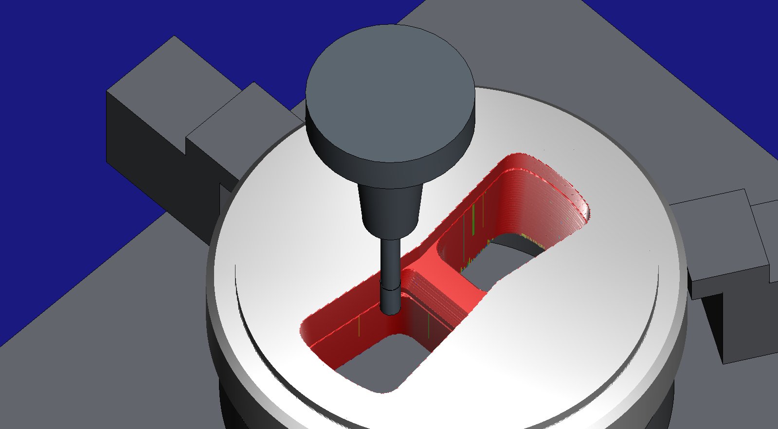
Finishing the upper plate: both portholes are through and the bridge's rear-tip face lies between them. Captured while the play ran, on HiNC 3.2.43.
All tools are generic solid carbide with a TiAlN coating (chosen). The agent's own CAM wrote the programs: Z-level roughing with ramp entries, Z-level finishing, rest machining for the long-neck tools, and a check of every part of the tool wider than the cutter against the stock; the nearest is T7's holder, 7.0 mm above the exit face at the deepest slot floor.
How the agent managed the work
- Pass criteria first. The criteria (a clean run and holder clearance, the porthole roughing's power and time, the long-neck D3's deflection with a rule for when the fin relief should go to EDM, and the die against its model at 0.25 mm with the fin-tip bearings as a stated exception) were written and committed before the first play; later changes to how a criterion is read are recorded beside them, and no criterion was rewritten.
- Coarse first. Every set-up was played at 1 mm (0.5 mm for the relief) before the acceptance at 0.25 mm; the D3's loads were read on a block cut down to two slots at 0.03125 mm.
- Its own check before HiNC's. After HiNC's first play the agent wrote a z-map replay of its own programs (rapid moves through stock, rapid moves within 0.3 mm of it, the deepest axial engagement) and ran it on every program before every later play.
- A shared server. The plays ran on a 32-thread server shared with ten other product cases, on a private instance; the acceptance waited for the shared lock that lets one whole-case play run at a time.
- Where a person stepped in. The owner moved this case from the reserves into the product cases on the day it was found. No second agent rebuilt the case or reviewed its claims.
The criteria as they were committed before the first play:
| # | Criterion |
|---|---|
| A1 | every program runs to its last line and touches the stock |
| A2 | no warning, error or collision (tool, shank and holder against fixture, machine and workpiece) in NC Diagnostics, Step Diagnostics or NC Manipulation |
| A3 | the agent's own check: at every feed point, every part of the tool wider than the cutter at least 5 mm above the stock within its radius; parts narrower than the cutter run inside the cavity the cutter opened |
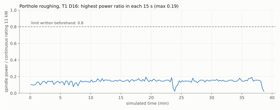
| B1 | the porthole roughing, T1: spindle power and torque at most 0.8 of the continuous rating (11 kW) at every step |
| B2 | T1's tool stress at most 0.5 of yield |
| B3 | T1's simulated time within ±15 % of the agent's estimate (path length over feed) |
| C1 | the D3 in the fin slots: tip deflection's 99th percentile at most 30 µm, its peak at most 50 µm |
| C2 | the D3's shank (Ø6, 40 mm above the tip) and holder nose clear of the stock |
| C3 | the D3's tool stress at most 0.5 of yield |
| C4 | a rule fixed beforehand: if the fin relief needs more than 4 h at loads that pass C1–C3, the report recommends sinker EDM for it and keeps the milled program as the evaluated alternative |
| D1 | at least 99 % of the points on the milled faces within ±0.15 mm of the design, all within ±0.30 mm |
| D2 | an expected exception, counted apart: the fin-tip caps of the relief, narrower than the D3, stay at the depth of the fin's sides, leaving a bearing up to 0.8 mm longer than drawn |
| D3 | no point more than 0.15 mm into the design, exceptions included |
| E | every program: spindle power and torque at most 1.0 of the continuous rating, tool stress at most 1.0 of yield |
| F | every program's and each plate's simulated time, reported beside the agent's estimate |
The dilemmas
Two dies in one paper
Situation. The paper designs an initial die (Fig. 2), then corrects it in four steps; the figures of both appear side by side. Risk. Built from Fig. 2, the case would machine the die its authors showed bending the profile. Noticed on reading Section 4 and Table 3 before modelling. Resolution. The case builds the proposed die of Fig. 21 (step 4), the one that was made and extruded; SOURCE.md says so. Evidence. The model carries porthole 2's R60 and 3 mm offset, the modified pocket, the adjusted bearings and the chamfered bridge.
Dimensions the drawings only show
Situation. The portholes' long edges, the pocket's outline and the right-hand fin spacing are drawn, not dimensioned. Risk. A misread figure gives a die that is not the paper's. Resolution. The agent set each figure's scale from a stated dimension (the Ø180 circle, the 90 mm height, the 95.95 mm profile) and measured the rest, marking every value in the numbers file. Evidence. Two values the paper states and the model derives agree: porthole entrance areas 1927 / 1663 mm² against 1960 / 1702 (−1.7 %, −2.3 %), and a profile of 1260 mm² against the 1237 mm² that the extrusion ratio implies (+1.9 %).
A source note with two errors of its own
Situation. The case's own source note, written when the case was collected, gave a “ram speed 10.73 mm/s” and said FDAC is machined before hardening. Risk. Wrong premises carried into the process and the page. Noticed on reading Table 2 and choosing the tools. Resolution. 10.73 is the extrusion ratio (the ram speed is 3 mm/s), and FDAC is sold pre-hardened, so it is milled at about HRC 40; both lines were corrected before the first play.
One side cannot reach everything
Situation. The portholes' outer walls open 7° towards the lower plate, while the bridge's top chamfer opens towards the press. Risk. From either face, one of the two is an undercut. Resolution. The upper plate is machined from its joint face (portholes through, welding chamber, the bridge's 50° rear wedge), then turned over for the two top chamfers alone; the CAM builds each set-up's reach from sections that shrink with depth. Evidence. The upper plate's two set-ups played with no collision and their milled faces came within ±0.15 mm of the model (100 % and 99.9 % of the points).
Bearing lengths made from the back
Situation. The bearing is wire-cut through the 40 mm plate, yet its length varies from 1.2 to 24 mm along the profile (Fig. 10). Resolution. The relief behind the bearing is milled from the exit side to a depth that leaves each segment's length: the agent assigned every point of the relief to the nearest profile segment and got 16 depth zones.
Fin tips shorter than the cutter
Situation. At each fin tip the paper's bearing (1.2–1.8 mm) is shorter than along the fin's sides (2.0–2.3 mm), but the tip's zone is narrower than a Ø3 cutter. Risk. A cutter that reached the tip's depth would shorten the sides' bearings. Resolution. The CAM leaves the tips at the sides' depth; the criteria named this before the first play as an expected exception (the tip bearing up to 0.8 mm longer than drawn, for EDM or hand work). Evidence. The 192 points on those caps kept 0.76–1.20 mm of stock, up to 0.4 mm more than the 0.8 mm named beforehand. The same effect turned out to reach further than the criteria named: wherever a bearing zone is shorter than its neighbours (so deeper from the back) and narrower than the cutter, the relief floor stays at the neighbours' depth: the sides of the first three left-hand fins keep 1.0 mm, the outer fin's tip 2.2 mm. On the relief outside the profile this is 1.9 % of the surface.
Two to three steps a second
Situation. The first play advanced two or three steps a second. Noticed from the step count. Resolution. Probes with physics and collision detection on and off were all as slow; one step per spindle revolution played 486 steps a second. The cause, found in another case's record, was the build script setting the fixed motion step's rotary resolution to 1°, which gives the tool's mesh 360 faces a turn; left at its default, the D3's fixed 0.25 mm step played three times faster.
Rapid moves through stock
Situation. HiNC's first play reported four Play-RapidCut--Detected, up to 27 mm deep and
152.8 mm³. Noticed in the step messages. The agent's own replay of the same program on a height
field found no such cut: the rapid crossings between levels ran the tool's edge along the roughing
wall with no clearance, and at 1 mm width the wall's residue was swept by the 32 mm flute
(27 × 11 × 0.5 ≈ 150 mm³). A rapid that close to a wall is bad practice on a machine too.
Resolution. The CAM keeps every rapid 1 mm off the walls, lifts before a retract, and feeds out of
narrow cuts; a probe with the tool grown by 0.3 mm checks every rapid. Evidence. The same set-up
replayed with no step message.
The two checks side by side; the fix added less than 3 % to the programs' time:
| The agent's height-field replay | HiNC | |
|---|---|---|
| Before the fix | no rapid through stock | four Play-RapidCut--Detected, up to 27 mm deep and 152.8 mm³ |
| Why | the rapid crossings between levels ran the tool's edge along the roughing wall with no clearance; a height field of the exact geometry cannot see that | the 1 mm grid leaves a quantised residue on the wall, and the 32 mm flute swept 11 mm of it: 27 × 11 × 0.5 ≈ 150 mm³ |
| Readings at those four steps | — | spindle power 3.57 of the continuous rating, force 29,000 N, tool stress 4.1 of yield; without them the roughing's highest power ratio at 1 mm was 0.33 |
| After the fix | a probe with the tool grown by 0.3 mm finds no rapid that close | no rapid through stock, no step message |
Two more faults the agent's own check caught
Situation. The height-field check found a 95 mm pass along the relief's wall in the D3 program, and a 14 mm feed plunge into uncut steel. Risk. Wasted hours, and a broken Ø3 tool on the first plunge. Resolution. The rest region had left a 0.05 mm band on every wall, and paths grouped by their centroid gave one slot the wrong entry height; both were fixed before HiNC played them, and the deepest axial engagement fell to 0.2 mm.
A grid coarser than the step-down
Situation. At 0.5 mm width HiNC read the D3's 0.1 mm step-down as 0.3–0.6 mm and its deflection as 444 µm. Risk. Judging the tool on loads several times too high. Resolution. A block cut down to two slots, with the other programs' work already taken off, played the D3 alone at 0.03125 mm; its program took four step-downs in 3 mm bands.
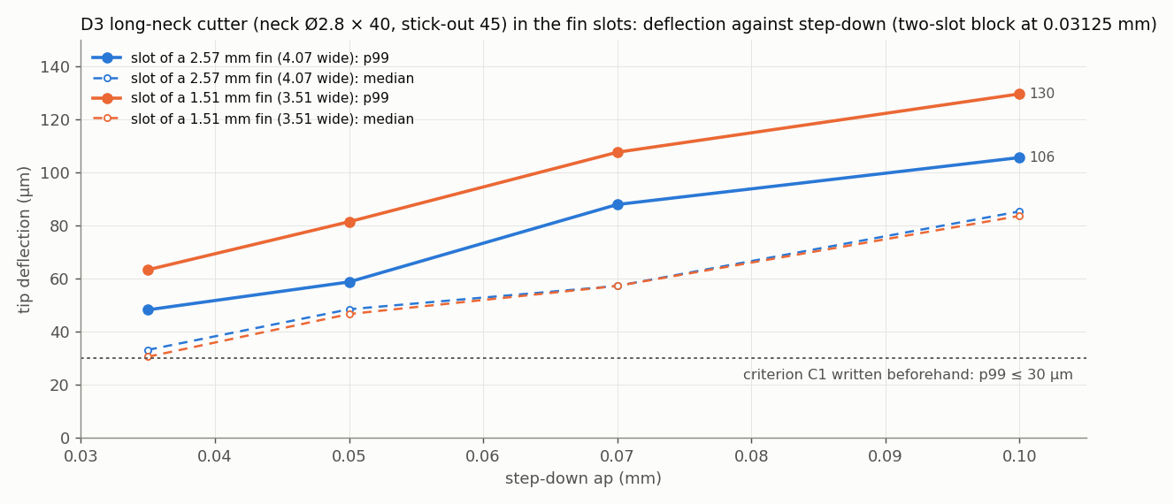
The fine play of the two-slot block (66,007 steps, 47.8 minutes simulated, no message), band by band:
| Step-down | Slot of a 2.57 mm fin (4.07 wide): p50 / p99 / peak | Slot of a 1.51 mm fin (3.51 wide): p50 / p99 / peak | Force, p50 | Tool stress, highest |
|---|---|---|---|---|
| 0.1 mm | 85 / 106 / 106 µm | 84 / 130 / 143 µm | 6.9 N | 0.13 |
| 0.07 mm | 57 / 88 / 106 µm | 57 / 108 / 143 µm | 4.7 N | 0.13 |
| 0.05 mm | 48 / 59 / 64 µm | 47 / 81 / 108 µm | 3.9 N | 0.10 |
| 0.035 mm | 33 / 48 / 59 µm | 30 / 63 / 86 µm | 2.6 N | 0.08 |
Evidence. The deflection follows the force at about 12 µm/N; at 0.1 mm the 99th percentile is 106 µm in the 2.57 mm fins' slots and 130 µm in the 1.51 mm fins'; at 0.035 mm it is 48 and 63 µm; the tool's stress stays under 0.13 of yield. HiNC reports the depth as twice the programmed step-down in these slots; the agent did not find why.
Results and benefits
Measured on HiNC 3.2.43 at 0.25 mm unless stated.
| Measure | Value | Criterion |
|---|---|---|
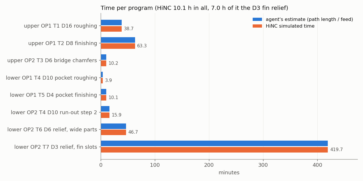
| Simulated machining time, both plates | 10.1 h (upper 1.9 h, lower 8.3 h, of which the D3 fin relief 7.0 h); no tool changes, turn-overs or EDM included | F: reported |
| Every program ran and cut | all eight ran to their last line (1,419 to 92,289 lines), each touching the stock (13,408 to 381,335 steps in contact) | A1 ✓ |
| Rapid cuts and collisions | 4 rapid cuts on the first 1 mm play, 0 after the fix; no collision in the acceptance (HiNC checks holder and shank against the stock); Step Diagnostics and NC Manipulation empty in every set-up, NC Diagnostics only one Sys-Init--FileLines per program |
A2 ✓ |
| Shank and holder clearance, the agent's own check | the nearest is T7's holder, 7.0 mm above the exit face; the D3's Ø6 shank, 40 mm above its tip, stays within run-out step 2; necks thinner than their cutter run in the slot the cutter opened | A3 ✓, C2 ✓ |
| Porthole roughing, T1 Ø16 | spindle power 0.194 and torque 0.073 of the 11 kW continuous rating (0.142 and 0.053 of the short-term rating); tool stress 0.141 of yield; 38.73 min against the agent's estimate of 38.68 (+0.1 %) | B1–B3 ✓ |
| Milled faces within ±0.15 mm of the model | upper plate 100 % from the joint face (−0.144 to +0.100 mm) and 99.94 % from the billet face (−0.27 to +0.14); pocket 100 % (−0.014 to +0.142); the lower plate's exit side 96.1 %: the relief outside the profile 98.1 %, the core inside the profile, which the wire EDM takes out, 79.6 % | D1: three set-ups ✓, the relief ✗ |
| Fin-tip bearings, counted apart | 192 points kept +0.76 to +1.20 mm of stock: the fin-tip bearings come out 0.8–1.2 mm longer than drawn | D2: reported apart |
| Deepest cut past the model | −0.32, −0.29 and −0.28 mm on edges no tool touched (the turned blank's circular edges, the portholes' sharp openings); −0.78 mm on the relief beside the outermost left-hand fin, among its bearing zones' steps (not examined further); −1.34 mm in the core inside the profile, which the wire EDM removes | D3 ✗ |
| Loads, every program | spindle power and torque at most 0.2 of the continuous rating in all eight; tool stress at most 0.35 of yield in seven; the D3 reads 1.22 at 0.25 mm, where the grid is coarser than its step-down, and 0.13 on the fine play | E ✓ (the D3 on the fine play) |
| D3 deflection, 99th percentile, at 0.1 mm step-down | 106 µm (2.57 mm fins) and 130 µm (1.51 mm fins), peaks 106 and 143 µm, fine two-slot play | C1 ✗ (30 µm, peak 50 µm) |
| D3 stress | 0.13 of yield on the fine play (1.22 at 0.25 mm, where the grid is coarser than the step-down) | C3 ✓ |
| D3 fin relief time | 7.0 h (419.7 min): 4.9 h cutting, 2.1 h feed in air, 0.04 h rapid | C4: over 4 h, EDM recommended |
| Run cost on the shared 32-thread server | 34, 1.2, 1.8 and 36 min of play; peak memory 3.8, 1.3, 1.2 and 4.7 GB | — |
The four acceptance plays, one after another under the shared lock, on the shared 32-thread server while its load stood at 60 to 90:
| Set-up | Steps | Simulated time | Play | Peak memory |
|---|---|---|---|---|
| upper plate, joint face up | 413,415 | 1 h 42 min | 34 min | 3.8 GB |
| upper plate, billet face up (bridge chamfers) | 67,474 | 10.2 min | 1.2 min | 1.3 GB |
| lower plate, entry face up (pocket) | 89,177 | 14.0 min | 1.8 min | 1.2 GB |
| lower plate, exit face up (relief) | 1,048,925 | 8 h 02 min | 36 min | 4.7 GB |
The fin relief: the Ø3 cutter's neck reaches 40 mm below the chuck, which stays 7 mm or more above the exit face. Captured while the play ran, on HiNC 3.2.43.
The D3's 419.7 simulated minutes, split by the agent's height-field replay; the feed in air is the tool leaving a slot and coming down again at 300 mm/min where uncut steel splits a level in two:
| Part of the D3 program | Minutes |
|---|---|
| HiNC's simulated time, the whole program | 419.7 |
| cutting | 292.5 |
| feed in air in the slots (entries and exits at 300 mm/min) | 124.8 |
| rapid | 2.4 |
For a machining engineer. Before any steel was cut, HiNC confirmed that the porthole roughing is far inside the tools' strength and the power of the generic BT40 spindle it was set up with (11 kW continuous), gave the time of every program, and showed where a long-neck Ø3 cutter stops paying: seven hours for the fin relief, a tenth of a millimetre of bending at a 0.1 mm step-down, and bearing zones it cannot reach. That is the evidence behind the usual choice to sink the fin relief by EDM and mill the rest.
For a teacher or a student. A porthole die shows in one part why a die is machined from both faces (drafts that open opposite ways), how the work is split between milling and wire EDM, how bearing lengths are made by the depth of the relief behind them, and why a simulation grid has to be finer than the step-down it is asked to judge.
For someone weighing the approach. From a paper's drawings to an accepted simulation of both plates, the agent built the model, the CAM and its own checks; HiNC caught a rapid-move fault the agent's program carried and gave the numbers that draw the line between milling and EDM for the fin relief. The whole case, from reading the paper to the accepted plays, took one working session; the four acceptance plays together ran 73 minutes on the shared server.
Honest limits
- The die is a reading of the figures. The paper has no model. The plates' heights, the portholes' inner corners, the welding chamber's top edge across the bridge, the run-out steps' outlines and the relief's offset are measured off drawings or chosen; the two area checks bound the reading to about 2 %, not to a machining tolerance.
- Wire EDM, turning, hardening and polishing are outside the simulation. The die orifice and its bearing, the turned blanks, heat treatment, nitriding and the bearing's polish are named, not simulated. The fin-tip bearings the 3 mm cutter cannot reach are left for EDM or hand work.
- The cutting data are generic. Tools, holders and the spindle are generic; FDAC stands in for H13 and HiNC's shipped FDAC cutting parameters were used as they are. Loads are HiNC's model, not measurements; no die was cut.
- Deflection is not chatter. HiNC reports the tool's static tip deflection and its stress; it does not predict chatter or tool life, which decide a long-neck Ø3 cutter's fate at least as much.
- Loads at the acceptance width. At 0.25 mm the D3's step-down is finer than the grid, so its loads at that width are not used; they come from the fine play of two slots. HiNC reports the depth there as twice the step-down, for a reason the agent did not find.
- The part is rigid. The thin tongues between the relief slots (2.0 mm on the left fins) are modelled as rigid; how far they give under the cutter is outside the simulation.
- No blind build, no review. No second agent rebuilt the case from its record or checked its claims.
What a reader can take to their own case
- Check a reading of drawings against numbers the source states. An area or a ratio the paper gives, recomputed from the model, tells whether the scale and the outline were read right.
- Ask which face each feature is reachable from before writing a program. Drafts that open opposite ways mean two set-ups; building the cavity from sections that shrink with depth makes the reach a property of the program rather than a hope.
- Keep rapids off the walls. A rapid crossing with no clearance is flagged by HiNC as a rapid cut at a coarse grid and is bad practice on a machine; 1 mm of clearance and a lift before a retract cost almost no time.
- Replay your own program before the simulator does. A height-field replay that reports rapid cuts, near-misses and the deepest axial engagement catches CAM faults in seconds.
- Make the grid finer than the step-down you judge. Otherwise the simulator sees whole layers and overstates force and bending; cut the case down to a block and play it fine.
- Leave the fixed step's rotary resolution alone. It also sets how finely the tool is meshed; at 1° this case's plays crawled at two or three steps a second.
- Let the numbers draw the line between milling and EDM. A long-neck cutter's bending at each step-down, and the hours that step-down costs, are what a die shop weighs against a sinker electrode.
Source and licence
- Source: T.-T. Truong (Hung Yen University of Technology and Education; National Kaohsiung
University of Science and Technology), Q.-C. Hsu (NKUST, Department of Mechanical Engineering),
V.-C. Tong (Korea Institute of Machinery and Materials), J.-J. Sheu (NKUST, Department of Mold and
Die Engineering), “A Design Approach of Porthole Die for Flow Balance in Extrusion of Complex Solid
Aluminum Heatsink Profile with Large Variable Wall Thickness”, Metals 2020, 10(5), 553,
doi:10.3390/met10050553. Search terms if the link moves:
porthole die heatsink large variable wall thickness Truong Hsu Sheu,met10050553. - Licence: CC BY 4.0. The article states: “© 2020 by the authors. Licensee MDPI, Basel, Switzerland. This article is an open access article distributed under the terms and conditions of the Creative Commons Attribution (CC BY) license.” The licence gives the material as is, without warranty.
- Attribution: “Die and profile geometry after T.-T. Truong, Q.-C. Hsu, V.-C. Tong, J.-J. Sheu, Metals 2020, 10, 553, doi:10.3390/met10050553, CC BY 4.0. Die model and machining set-up by Tech Coordinate's agent.”
- Changed from the original: the article has no model; the three-dimensional die (plate heights, the portholes' inner corners, the welding chamber's top edge, the run-out steps' outlines, the relief's offset) is the agent's reading of the figures, with every value marked read, measured, derived or chosen; FDAC stands in for H13; the 0.2 mm waves and the block's top notch are on the wire-cut bearing and are not in the milled model. The paper's figures are not reproduced here; the pictures are HiNC renderings of the agent's model, and drawings of that model and charts of its runs made by the agent's own scripts.
See Also
- Heatsink Porthole Die, Optimized — HiNC's feed optimization on this case: both plates 13 % shorter, and no feed keeps the Ø3 fin-relief cutter within 30 µm
- Showcase — the other cases and how a case page reads
- Replay Acceptance over the HTTP API — watching a play and accepting on evidence
- Cutter Geometry — holder profile, neck and stick-out